
Hello,
Going to strip my first Manx/Inter SOHC engine:
- Anything special I should take care of?
- Is there anything easier to do while engine in frame? Like taking valves springs off,
unscrewing crank nut or whatever...
- And for rebuild?
Christian It depends heavi…
- Log in to post comments
Crackyour big fixingswhils…
Crackyour big fixingswhilst itsin theframe,drivesprocket, bevel drive,cam drive, cambox andhead ifposs, anything thatmayprovetightanditswobbling around on thebench.
I usuallyleave itintactsoyoudonthave a loose piston orshaftflailing around but itsalittleheavy. IhaveaswivelvicethatIstand it in tostrip thebits andpiecesbefore partingthecasings. Measureeverything,counteverything and documentit Photos photosphotos.
Shimson thebevel drive, gap in theoldhamcoupling, turms onyoupiston oilingbolt. Keep your head and camboxboltsin their respectivelocations, cylinder basegasket/ shim(s).
AsArne,saidgeta bookI gotoneifyou need a copy. Itsnotcomplicatedbutdonerightyou probablynoteverneed to do itagain. Is itMagnesium casing? Howfaryou going andwhy?
There isasmall screwon the right casing lowerrearcorner,dontforgetit.
Ill help where Ican
Goodluck, Itsanice motor towork on
Jon
- Log in to post comments
Arne, Got enough room to d…
Arne,
Got enough room to do it, and also a few tools. Holding the engine on the bench is of course essential. Am a little poor in literature actually, what I have now is :
- Inter Parts List 46-49
- Don't know how you call it in English, it's a drawing of an open engine from Motor Cycle
- Notes on the assembly of Norton cammy engines by Georges Cohen
- Servicing the Double-o.h.c. "Manx" Nortons by Bruce Main Smith
Last one is a multiple times copied copy and is not that easy to read.
Jon,
Was thinking of taking valves, cambox, head, barrel and piston off. But now would like to know the compression ratio before taking things off. And correct me if I'm wrong, but an"easy" way is to put the spark plug hole "vertical" and fill up with oil until the first thread with piston TDC.
Could still take the cambox off and crack the big fixings as you said.
Where is the piston oiling bolt? And how many turns should it be turned or unturned?
Would appreciate your book, and yes it's Magnesium casing, not to be heated with a torch flam!. How far don't know yet but far enough to completely clean it because it had R40 in it and was sleeping more than 23 years with some in the engine.
Thank you for your help.
Regards,
Christian
Attachments
1-eclata-c-moteur-jpg
- Log in to post comments
The engine in your diagram…
The engine in your diagram is a long-stroke featherbed Manx, which will have few parts in common with an International engine.
You don't say what engine you have, or what frame it's in. That does make a difference as to how you go about removing the engine, and how you begin to examine it
I would suggest undoing the engine sprocket nut before dismantling the primary or final drives. I have a large socket for the engine sprocket nut, a long lever and a foot on the rear brake pedal does the trick. Put it in top gear first....
The ohc engines were race engines designed to be serviced in the frame. You can take the cam-box off if you are careful.. Undo the four bolts holding the cam-box to the long head nuts, and the large nut at the base of the vertical shaft. The cam box will then come off, be careful as you wriggle if out from under the frame top tube. Just don't let any of the bits fall off, particularly if you have the Hoffman self-aligning ball bearings in the vertical shaft. ... People were using the SKF EE6 bearing even in the early '50s when the Hoffman bearing was readily available (at a price) due to this problem
The external hairpin valve springs were intended to be accessible so you could replace them during a race, one at a time. Don't take the valve springs off before removing the head. You don't want a valve to drop in.
If you take the cylinder head off, the engine will me smaller and much more easily managed. But don't forget to take a good look at the combustion chamber and joint faces as you do so.
Paul
- Log in to post comments
Christian I will be back w…
Christian
I will be back with a better response to your questions later, but could you please state the year of your bike ?
Regards
Arne
PS. Mine is a 1948 manx
- Log in to post comments
Previously paul_standeven…
Previously paul_standeven wrote:
The engine in your diagram is a long-stroke featherbed Manx, which will have few parts in common with an International engine.
I would suggest undoing the engine sprocket nut before dismantling the primary or final drives. I have a large socket for the engine sprocket nut, a long lever and a foot on the rear brake pedal does the trick. Put it in top gear first....
Paul
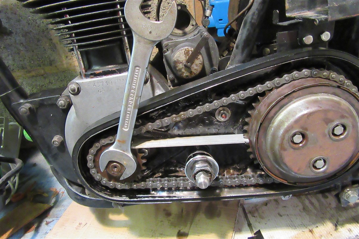
I always use a sprag for engine sprocket nuts as I think it's kinder to the power train - and never wedge things between the back wheel spokes as some barbarians do!
Any old bit of alloy or mild steel will do provided it's strong enough to take the compressive force. The pic shows it in position for tightening.
Ian
Attachments
sprag.jpg
- Log in to post comments
Hi. I thought some of you…
Hi.
I thought some of you might be interested in a jig that I built to enable me to torque up (and undo) the two nuts on the SOHC camshaft.
Using nothing more than an angle grinder, a pillar drill and various taps and dies, itâs made from a piece of right-angled 3â high grade stainless â the type used in the construction industry â mine came from an offcut I found in a skip at work. Itâs tough stuff and I havenât found a need to harden the metal to cope with the torque involved. Youâll need a piece about 8â long.
Cut a suitable size piece on which to mount the cam-box. Start by drilling and tapping two holes for the long bolts (itâs ?â thick so it has plenty of âmeatâ to take the bolts) that hold the cam-box. Grind a cut-away for the top bevel housing. Drill two larger holes to clear the pad adjusters if required.
From whatâs left of the steel, cut two plates 1?â X 3?â. Mark out an 11mm or 7/16â square the centre of which should be ?â down from the top (narrow) edge on one of the plates. Mark the centre of the square. Now get the other plate, align and clamp the two together and drill through both using a 10mm drill. Take the first plate and open this out to 11mm or 7/16â using a square file to neatly fit the square end of the camshaft.
Take the second plate and using the 10mm hole as a guide, drill it out (using a âblacksmithâs drill) to 7/8â. Place the L/H threaded camshaft nut over this hole and mark around it â I used insulating tape â and file it out to shape. All this is bloody laborious but worth it in the end!
Mount the cambox including the shaft, spacers, cams and bearing, horizontally on the jig. Put the L/H threaded nut on and then place the second plate on the nut - check to see if a spacer plate or washers are required to enable it to sit true over the nut.
Once this is done acquire two suitable studs. I used two old Roadholder bottom yoke studs and cut the thread further on the âlongâ side. Then take the first âsquare holeâ plate and drill two ?â holes 3â down from the top edge and about 7/8â apart. Going back to the cam-box on the jig with the spacers and the second âhexagonal holeâ plate over the nut, place and align the first âsquare holeâ plate and using the ?â drill bit mark the second plate. Drill the second plate and repeat the above procedure to mark and drill the spacer plate and the main body of the jig.
Finally drill the two plates out to the require stud size. Then drill and tap the main body of the jig to take the studs. Remember to use the pillar drill to start the taps off âsquareâ.
All thatâs needed then are some nuts for the studs and an 11mm or 7/16â square section socket to torque up the L/H threaded nut â these are available fromhttp://www.davidharriesstore.co.uk/ or throughhttp://www.impactsocket.co.uk/ who will tell you who your local stockist is.
Quite a bit of effort to make, but, it means your not risking levering on the bearing behind the large bevel gear nor are you relying on one bevel tooth to take the strain when undoing the nuts!
Cheers.
Ian (1948 350 Manx).
Attachments
jig-1-jpg
- Log in to post comments
Yes it's a mag engine, no…
Yes it's a mag engine, no oil seal.
Turning the crank by LH nut before, it was possible to feel that at least one bearing was really tired. But crank cheeks could have moved.
When it will be apart, will get in touch with Stu to be guided on the good path.
I agree with you about historical parts, but for the moment the owner is dreaming about driving it (which actually means thrashing it) Like a lot of people who don't really know about mechanics, he thinks that for a thousand € he will be soon having fun with his Dad's bike. But working by my side, he is discovering that it takes TIME. And money too.
Christian
- Log in to post comments
GB threads for dumb FR …
GB threads for dumb FR
Very interesting article on bolt/nut head size, helps me dive into a part of the ocean of GB bikes.
Thank you Jon.
- Log in to post comments
Wasn't too long? Took air…
Wasn't too long?
Took air filter, carb, foot rest and exhaust off today. Quite easy except the owner went a little bit too fast for taking off one carb's hose and broke the last thread :(
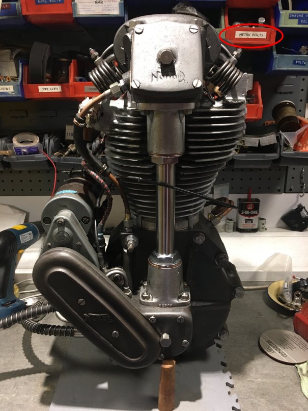
Found some metric fasteners on air filter.
Intake valve have the rocker acting directly on the stem :(
Thinking of taking off the oil pump soon, I've been looking around to find some 9/32" 26 tpi BSCY screws. Lot of people are selling taps and dies, but no screws and no nuts.
Where can I find that?
And if I should do them, what should be the diameter of the rod?
Thanks
Christian
- Log in to post comments
metric fasteners :))) …
metric fasteners :)))
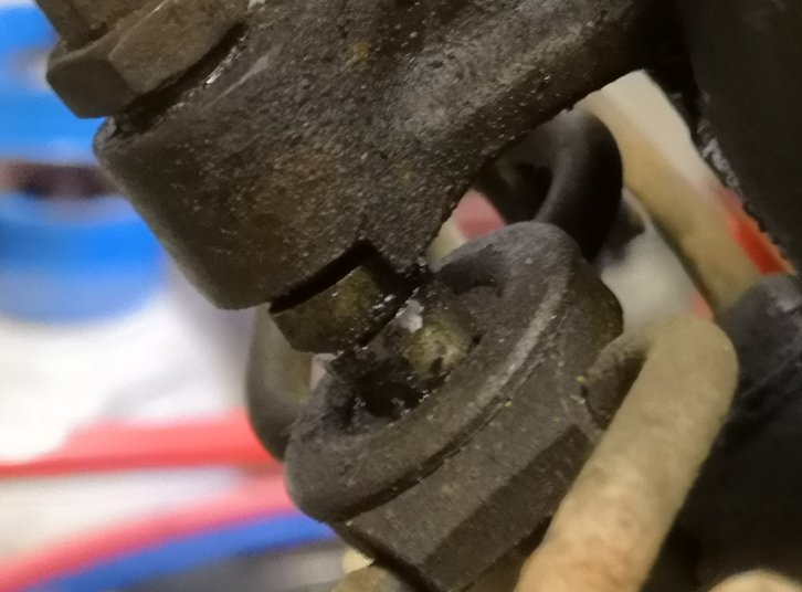
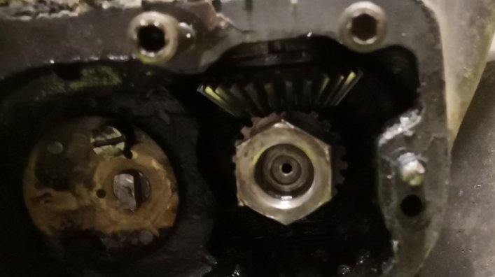
Well don't know if it's really the valve adjuster, because there is a screw and a nut on the rocker to adjust.
Looks like a "pellet" to protect the stem. BTW we had 0,6mm of play on admission valve and 0,7mm at exhaust.
Managed with the owner to let slip away some pictures.
When you look at it so closely, they do look a little dirty ^ ^ 28 years in a shed...
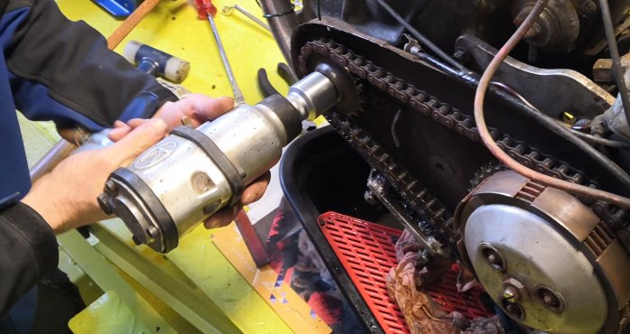
Today we managed to take the big nut off the crank LH side with a 1"3/16" socket. Might not be exactly the good one because we had to help it jump on the nut with a plastic hammmer. But with an impact wrench, I prefer a little too tight than a little too lose. And double check the thread before you press the button. At the end, some small marks on the flat parts of the screw, but not on the edges.
For RH side, we are going to need to be a little smarter not to spoil the bevel gearing. And the nut looks to be left handed. Is it true ?
I've already seen the vintagenorton caution, thanks ;-)
- Log in to post comments
Manx/Inter valve adjustment.
Hi Christian,
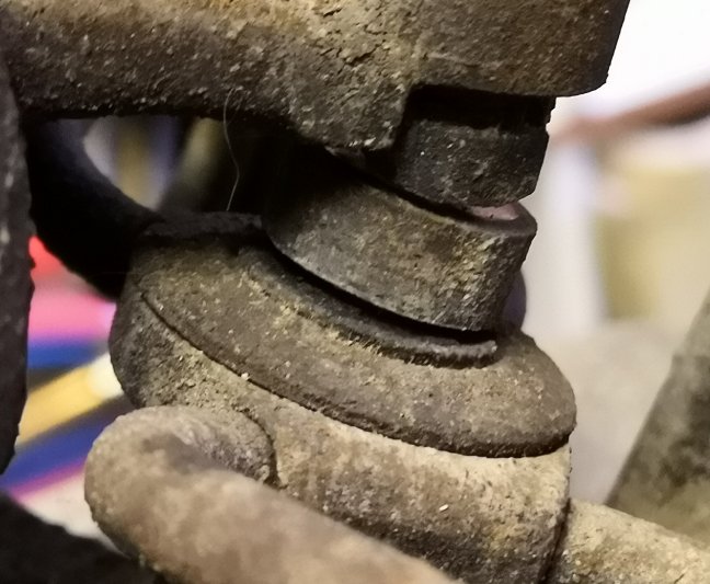
The photos show the tappets are correct although you have a valve cap on the exhaust but not the inlet. You need to take care with the rocker adjusters as it is easy to break the fragile split adjusting part. Before trying to dismantle these it will be best to heat the rocker ends and use some penetrating oil on the threads. First make sure there is a gap between the valve and tappet then undo the small locking nut while holding the adjusting hexagon still. Unscrew it a couple of turns but do not try to turn the large adjusting hexagon. Next use a piece of alloy to protect the centre contact pad and small lock nut so you can tap it gently with a hammer to loosen the taper fit where it fits inside the tapered adjuster. Remove the small lock nut and then carefully try and undo the adjusting hexagon. Do not use excessive force, if it does not move use more heat and oil. Be just as careful when you re-assemble and never try to adjust the clearance with the taper tight together. This set-up is tedious as you have to tighten the lock nut and check the clearance. If it is not correct then loosen it and the taper for each adjustment so it may take several attempts to get it right. Inlet is 0.3mm and exhaust is 0.5mm.
There may be a similar problem when you remove the left-hand nut and the half-time pinion from the crankshaft. This gear is also a taper fit into the crankshaft bevel gear. If you try a sprocket puller and use too much force it's easy to break or chip the gear teeth, use heat and a tap with a piece of hard wood and a hammer before using the puller.
Regards, Richard.
- Log in to post comments
Hi Jon,Yes I did get mail…
Hi Jon,
Yes I did get mail and tried to answer yesterday...
The thing is that it is not my bike and the owner would like to be there while working on it. And at the moment I just have a severe lumbago which tells me to sest each time I try to go to the garage :)
By the wat don't understand your :
Do we need a few introdutctory notes in the header...
Merry Christmas and Happy New Year to all of you
- Log in to post comments
Oups... Went to dismantling…
Oups... Went to dismantling without heating or any penetrating oil... Easily, it was tighten, but not too much.
Will be careful for re-assembling.
Glad to learn that there is a bucket only on the exhaust, was wondering about needing to file the stem's head to get the inlet valve off from its guide because of the hammering.
Really easy to take the LH nut off with an impact wrench. Took three tries to adjust step by step the power of the tool, and zzzzzzz it went off.
For the RH nut, what is the size of the socket? Is it a left hand thread? Do you put an old rag in the bevel box or try with the rope in the spark plug at TDC valves closed?
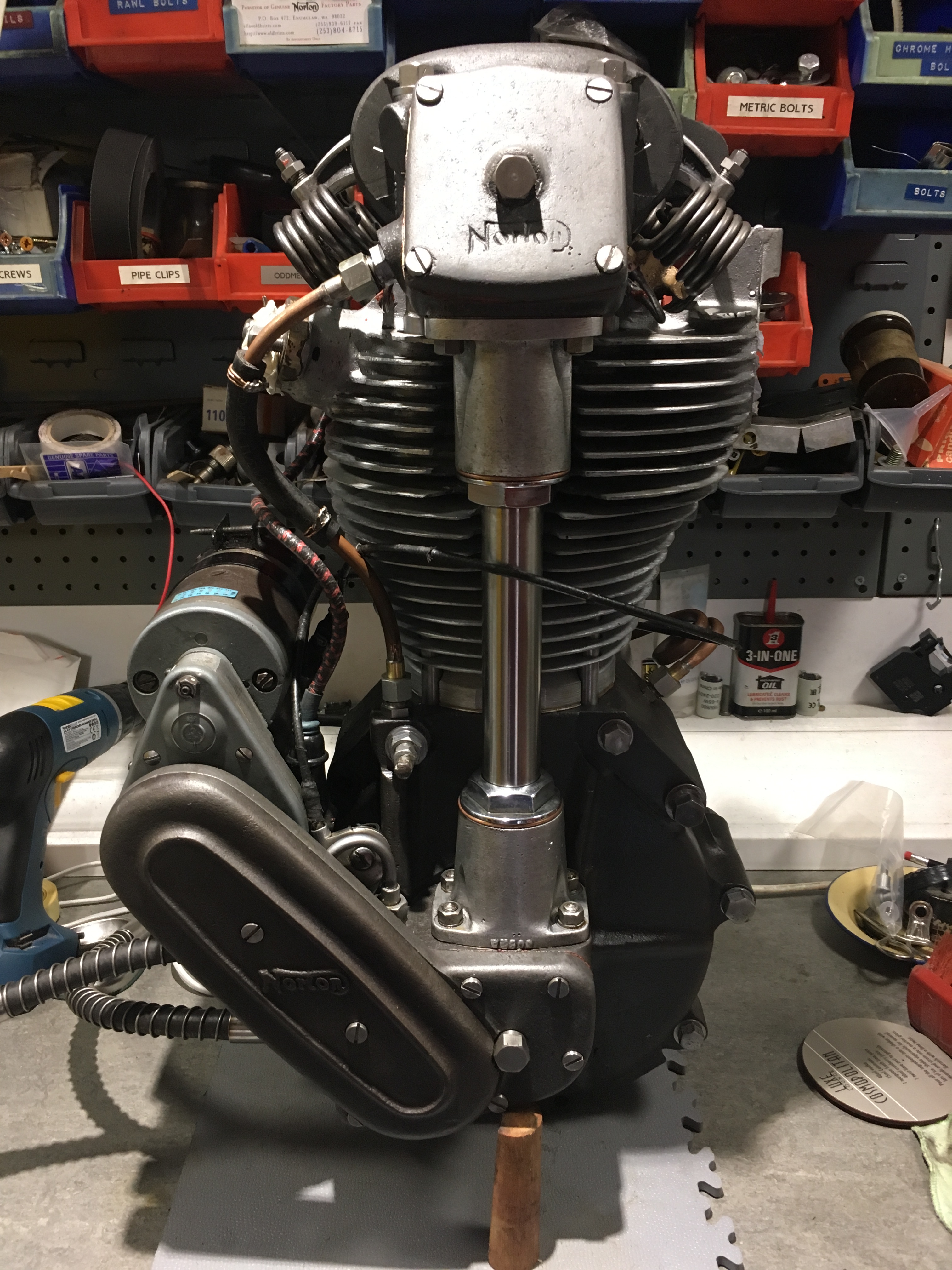
Looks nice your engine Jon, what have you done on it and how much time was needed to achieve that nice work?
- Log in to post comments
Here it is set up to undo…
Here it is set up to undo the nut holding the large bevel or for undoing the left-hand camshaft nut.......
Attachments
jig-2-jpg
- Log in to post comments
Beautiful ! ! ! We must…
Beautiful ! ! !
We must have some genes in common, let me introduce you my Black Magic Woman:
- Log in to post comments
It's refreshing to see this…
It's refreshing to see this passion that drives you Jon. And yes even if it might be a special one, the actual owner doesn't want to spread anything around at the moment.
Back is a little better thanks.
Should begin dismantling next week.
Best Wishes
- Log in to post comments
So you have the documents I…
So you have the documents I sent? The comment regarding Introductory notes refers t o the use of the web site in its new format. What is evident is that not many people are posting, but now its picked up again so notes not needed.
Have a great Christmas and post a picture or two of this special motor if you can. Interested to see it
Cheers
Jon
- Log in to post comments
yes
Hello yes best thing to do when doing any engine strip have good dump bins to put your parts in so you do not lose them and have a good SD cam handy and take loads of photos so you then can look back where thing went, and before any rebuild make sure every thing is cleaned properly, and inspect for any worn parts, if not sure get back to the NOC guys thats done these jobs before, yours anna j now have fun
- Log in to post comments
I'm lucky to have all your…
I'm lucky to have all your knowledge I can sit back on, thanks Jon.
Will be back to you, for sure.
- Log in to post comments
Looking for a socket to…
Looking for a socket to unscrew the RH nut off the crankshaft, was wondering if 59/64" is the one to look after?
Any idea?
- Log in to post comments
According to the numbers, it…
According to the numbers, it looks to be just a 1952 350 Inter.
Thanks Anna for you inputs, will do that for sure.
Cheerios
- Log in to post comments
In the Spares Dept:
You're going to need this:
SS11 C1_WHIT/SOC
and this:
SS11 C1_WHIT/SPA
- Log in to post comments
Thanks Michael, but it is…
Thanks Michael, but it is not really helping me for buying it somewhere.
What are these references referring to? Which manufacturer is this?
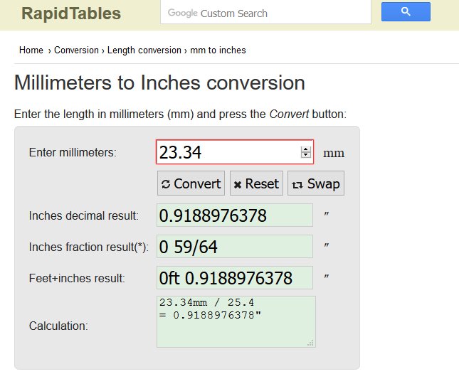
In a conversion table I can see that what I measured on the bike, 23,34mm, is 0.91889" or 59/64".
But when I then look at dealers shop, nobody is selling this size.
When looking on the net for a 59/64" Whitworth socket, all I can see are "square" ones.
Still have a lot to learn, so where am I wrong?
- Log in to post comments
Socket size
I have a note on the workshop wall where it says 1/2W = 23.37mm. 1/2" Whitworth sockets are quite easy to get.
Am I wrong?
- Log in to post comments
Jon, finally everything…
Jon, finally everything arrived this morning. Real job, thanks fot all that! Please tell me how much I owe you for all those valuable readings.
Should begin to work on it next year.
- Log in to post comments
I've picked up lots of…
I've picked up lots of Whitworth spanners in car boot sales. Very cheap. And especially useful if you need to grind one down to fit somewhere where access is tight.
- Log in to post comments
What michael is saying is…
What michael is saying is there is a spanner set and a socket set suitable for most of the fasteners on that bike in the Spares section under TOOLS.
OK got it, thanks.
I can never remember the sizes but will measure up tonight and let you know but the above are worth having and not expensive...
I've bought once at AN a whole set of tools, and they are not really working on my Englishs bikes... And a nice guy from another Norton forum gave me 4 old ones, and I'm doing everything with them.
- Log in to post comments
I've picked up lots of…
I've picked up lots of Whitworth spanners in car boot sales. Very cheap. And especially useful if you need to grind one down to fit somewhere where access is tight.
Interesting, let me first have a look of what I'll be in need for and I'll be back to you.
- Log in to post comments
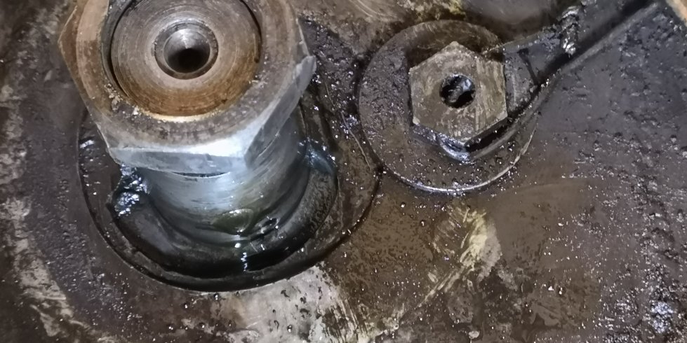
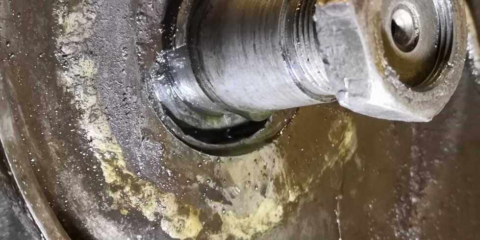
Last news of the engine :( …
Last news of the engine :(
RH crank sprocket came after asking him from gentle to roughly (heat, puller and a single hammer blow) but big surprise behind, crankcase is broken...
Is it usual on those engines?
- Log in to post comments
Ok good news. Will help…
Ok good news. Will help where I can. Was speaking with Stu about it, sounds quite a special one. Keep checking the settings as you strip it. Mine was completely non standard when Stu took the valve timing down but it was a strong pulling motor with good breathing.
Hows the Back.
Let us know how you progress....
pictures would be good...
- Log in to post comments
No Problem Chris. Happy to…
No Problem Chris. Happy to help if you have a query. Enjoy!
Jon
- Log in to post comments
Those metric fasteners.... …
Those metric fasteners.... they get everywhere!!! ;-)
Where did the valve adjuster go? was it missing or just wound out? or worn away?
7mm rod is slightly under for 9/32" but should get your job done. Interesting comment on John De Kruif site regarding thermal expansion when removing the pump. Take a look...
http://www.vintagenorton.com/2014/10/how-to-remove-inter-oilpump.html
Should you require the exact tool, Stu Rogers.... he inspected mine recently as i was unsure of tolerances.
Cheers
Jon
- Log in to post comments
Ah, I see what you mean . …
Ah, I see what you mean . The Bucket on the EX valve is common mod but not standard as I know. It helps when setting the angles with respect to valve stem length, rocker/ cam wear, valve seat intrusion and of course a replaceable wear item instead of hammering the top of the valve stem. It is more common on the exhaust valve due to the extra heat
As Richard says above, clearances and method for LH are sometime tricky but spend time to get them right.
Everything pictured looks in decent condition, again as per Richard, a good soak in release agent to clean up.
Pic is where you will end up :-)
- Log in to post comments
Left hand thread, I think…
Left hand thread, I think itt was 5/8 whit. But I stand to be corrected.
Cracked mag platform necessitated a weld. Outside my skills so Stu got it done for me. On the basis it had to be stripped to deal with the crack, decided to get the casting dipped in the di chromate tank. Needed to be stripped of all ferrous and non ferrous fittings then when complete all threads cleaned out and rebuilt. That took a 12month period. All items cleaned, bearings replaced, bore honed, new rings , cam box repacked, reassemble, timed and sealed up. For an 82 year old engine there was little wear and it it had clearly been well cared for.
- Log in to post comments
I collect them up for my…
I collect them up for my real bike, should it EVER need one...
;-)
- Log in to post comments
What michael is saying is…
What michael is saying is there is a spanner set and a socket set suitable for most of the fasteners on that bike in the Spares section under TOOLS.
I can never remember the sizes but will measure up tonight and let you know but the above are worth having and not expensive...
Cheers
Jon
- Log in to post comments
That’s a blow. The nut as…
That’s a blow. The nut as you must know now is 11/16” Whit (31mm). I have had this before on a very tired motor; the Late George Cohen helped me there.
Not sure but It looks like it’s been welded before. It’s a magnesium motor right? There is no oil seal here just a breather.
This is a specialist repair and I suggest you get in touch with Stu Rogers again. He will guide you in the right direction. With this amount of crank movement be prepared for some more issues inside.
It’s a special motor of significance in the history of the marque. The owner needs to work out what he wants,commit to spending some significant cash or move it on to someone who is prepared to revive it.
A bite in the ass.... but that’s old timers for you!
jon
- Log in to post comments
Its special Chris. The…
Its special Chris. The damage is repairable and if you got the contacts for that sort of work it will be easy enough. There is nothing unusual about the bottom end. Clean down the outers then measure and photo as you go.
If its still in the frame loosen the oil drain plugs two on pre war they can get pretty stuck especially if only the one has been used.
I emailed an article on fasteners and bolt/nut head size...
It looks like his dad had plenty of fun with it!!
Cheers
J
- Log in to post comments
......and again for doing…
......and again for doing up the nut...
Attachments
jig-3-jpg
- Log in to post comments
....finally setting the to…
....finally setting the torque. For some reason this site wouldn't let me load 4 photos on one post!!!!
Cheers.
Ian.
Attachments
jig-4-jpg
- Log in to post comments
More on this issue of nut…
More on this issue of nut tightening:
http://www.vintagenorton.com/search?q=camshaft+nut
and my version of Ian's jig. Meant for stabilizing camshaft to tighten LH nut after torquing opposite RH nut.
http://www.vintagenorton.com/2017/12/mikes-take-on-oz-cambox-jig.html
Great minds.............in spite of what my domestic supervisor may think.
- Log in to post comments
Previously christian_wyss…
Previously christian_wyss wrote:
Arne,
Got enough room to do it, and also a few tools. Holding the engine on the bench is of course essential. Am a little poor in literature actually, what I have now is :
- Inter Parts List 46-49
- Don't know how you call it in English, it's a drawing of an open engine from Motor Cycle
- Notes on the assembly of Norton cammy engines by Georges Cohen
- Servicing the Double-o.h.c. "Manx" Nortons by Bruce Main Smith
Last one is a multiple times copied copy and is not that easy to read.
Jon,
Was thinking of taking valves, cambox, head, barrel and piston off. But now would like to know the compression ratio before taking things off. And correct me if I'm wrong, but an"easy" way is to put the spark plug hole "vertical" and fill up with oil until the first thread with piston TDC.
Could still take the cambox off and crack the big fixings as you said.
Where is the piston oiling bolt? And how many turns should it be turned or unturned?
Would appreciate your book, and yes it's Magnesium casing, not to be heated with a torch flam!. How far don't know yet but far enough to completely clean it because it had R40 in it and was sleeping more than 23 years with some in the engine.
Thank you for your help.
Regards,
Christian
Christian; tendto pull themotorcomplete astherearesomechecksyouneedto makewithregard to thecamdrive shaft beforeyouseperatestuff. BecauseIamnotaraceengineeror anykind of expertItend to measureall thingsanddecide onwhat seemsto be in tolerance orcanbeimproved. Bevelgear backlash /setup andoldham couplingfloatareimportant. Valvetimingshouldbepreservedasthere are many variationsthatwork depending on how youwant themotror toperform. Theoiling bolt is at thetop of thecasingsto therearofthecylingder. You canregulate theoilfeed to theback of thepistonskirt, its a running adjustment really butstart at3/4of aturnand widentill youseebluesmokeonahigh tickover,thenease itback Asprevious,photos aresohandywhenyournotsure.
Willcopy thedocuments Ihave and forward if youwishemail meon J_N_Newton@Hotmail.co.uk
Best regards
Jon
- Log in to post comments
OK Jon, we'll meet by mai…
OK Jon, we'll meet by mail.
Best regards,
Christian
- Log in to post comments
Did you get Mail Chris? It…
Did you get Mail Chris? It's gone very quiet on here, Do we need a few introdutctory notes in the header...
J
- Log in to post comments
Let me add here a plug for…
Let me add here a plug for an invaluable book for anyone with a Garden Gate Inter or Manx. A real work of art and a great help to me.
Dutch author Niels Schoen has produced a book about his Manx No. C11M14566
- Log in to post comments
Yep, beautiful book for th…
Yep, beautiful book for those with a Garden Gate.
- Log in to post comments
Previously Michael Rettie…
Previously Michael Rettie wrote:
Let me add here a plug for an invaluable book for anyone with a Garden Gate Inter or Manx. A real work of art and a great help to me.
Dutch author Niels Schoen has produced a book about his Manx No. C11M14566
EngineersArt - a beautifullycrafted document.
- Log in to post comments


Christian
It depends heavily of what facilities you have.
I find it crucial to have a engine stand, if not you might find it easier to perform some operations while the engine is in the frame...
Have you got any literature to guide you ?
Regards
Arne