
I have a 1961 ES2 rebuilt and bought from old parts.
Can someone please tell me the resistance of the correct ignition coil as I think mine is drawing too many amps - 5 amps with the engine not running.?
Thanks
What voltage are you running…
- Log in to post comments
Resistance?......
Voltage? The smaller ignition coil (as later commando) 40mm for 6V has a resistance of 2 ohms. So would be 3Amps. Is your problem with 6V or 12V with an 'original' ignition coil (52mm) and is the 5 Amps real? The built in ammeters are notoriously inaccurate. If it works and doesn't get too hot in usage ie riding down the road and your battery maintains charge, then go with it. Of course burning of the points might be an issue.
- Log in to post comments
More facts
Thank you all for your advice.
I have finally been able to do a lot more measuring, please see the attachment.
My problem is that the system is not charging enough.
I think I need a new stator. Is it possible to use a three wire powerbox (3 phase?) with a two wire stator (single phase)? (I have been offered a single phase stator locally)
Can any body tell me what the problem is?
As I live a long way from the UK with a very weak currency, I need to be certain of the problem before I import anything.
- Log in to post comments
The tests..
are quite good. They show a shortage of DC from the Power Box. Yet you are getting 4.5 Amps from the alternator?? You do not say how or where you are measuring these AC? AMPS. This post started with a 'coil resistance' problem. But now it is shortage of charge problem!
The Power Box is the first suspect and easy to replace. Replace it with a basic rectifier. Either one of the newer encapsulated items or the original black painted type. Run engine up as before and monitor DC amps produced (testing of alternators and A Regs on aoservices web site) or monitor battery voltage. If charging is re instated then Power Box is suspect.
Why is there a question about 3 wire Power Boxes? Your stator is more than likely to be the original 6V pre RM19. NOT NOT 3 phase.
- Log in to post comments
Thank you Alan
Originally I thought that the coil was drawing too much current (I think it's a 6V coil - it has a 6 stamped on it), every thing else is 12 V. So I fitted a resistor to reduce the current.
According to the internet, the stator is from a 1972 Rocket or Triumph 3 cyclinder. So I assumed it is 12 V, and made everything 12 V.
The stator output amps I measured using a multimeter set to ac in the three wires coming from the stator. One wire was 4.5 amps, one was 1.2 amps. Can this be right, surely all 3 wires should deliver approximately equal current?
The reason I asked about 3 phase is that the new Wassel powerbox I have has three input wires. The new stator I have been offered has two output wires. I see from Norvil catalog that both 3 and single phase alternators are available. Can I connect a two wire stator into a three wire powerbox? How?
I will try using a basic rectifier. When I bought this old bike it had an old red rectifier - a stack of fins with three wires leading into it. I hope I can find it.
Thanks again.
- Log in to post comments
You can connect a 2 wire…
You can connect a 2 wire single phase alternator to a 3 yellow wire 3 phase rect/reg by just connecting to any 2 of the 3 yellow wires.
Your coil is a 12V coil based on its resistance, a 6V coil would be 1.9 Ohms or there abouts.
The Lucas single phase alternator has 6 coils but they are arranged so 4 coils are connected and 2 coils. So when testing any 2 wires they will either be connected to 2 or 4 coils and the 4 coils will show more amperage.
Read more here
http://www.aoservices.co.uk/info/ALTERNATOR_COLOURS.pdf
- Log in to post comments
It is not...
The coil is 6 V as this is written on it. I have already posted the coil resistance on here after I measured it! DO NOT use the old red rectifier, that would be original Selenium, very leaky maybe dead. Use encapsulated or a tested black paint one.
Again there is a problem in measuring the AC. The coils are connected in 4 coils and 2 coils so under total output we should have 5.7A. In this case. Although I wouldn't advocate measuring alternators like this. All meters will be calibrated for 50c/s (in UK) with a Sine Wave. The Lucas alternator will run up to several hundred cycles and the shape of the waveform is 'disgusting'. But having said all that the AC Amps here are about right. To measure the amps on a Lucas alternator. Use a reliable Silicone rectifier, and measure the DC into the bikes wiring with the head light as the load.
- Log in to post comments
Your – and Alan’s -…
Your – and Alan’s - statement about the 2 and 4 coils showing different amperages ties up to a degree with my measurements (4.5 amps, 1.2 and 3) although 1.2 seems a bit low.
I’m going to test the set-up as detailed in Alan’s document.
I should have read this a long time ago.
By the way, the wire colours from my stator are black/white, black, white/black.
- Log in to post comments
Thank you Alan..
I'll what you say.
I'll use the rectifier box from my Commando.
- Log in to post comments
Rectifier box?
If the Commando has a 'rectifier box'?? This might be a regulator/rectifier, this is not what I am saying use. Use a basic Bridge Rectifier-encapsulated (£7 from me) or a good black painted Lucas item.
- Log in to post comments
Alan's tests...
.... - the results are added to the previous attachment.
I have gone through his paper and done exactly as he stated.
One coil group has a lower resistance than recommended (0.6 ohms i o 1 ohm)
The resistance to earth of the 3 wires is not infinite, ranges from 1.6 Mohms to 10 Mohms.
I don't know if these are real or spurious on my multimeter. Readings were taken from the 3 wires to the stator body.
It would be very much appreciated if someone could tell me if the stator is still sound.
I intended to try the Wassell Power Module which is fitted to my Commando, but it has only two stator input wire, not 3 as the ES2 stator has output leads.
Can a 3 wire stator work satisfactorily with a 2 wire Power Module?
Everybodys help and advice is very much appreciated. Hopefully I will soon know if my stator is ok.
- Log in to post comments
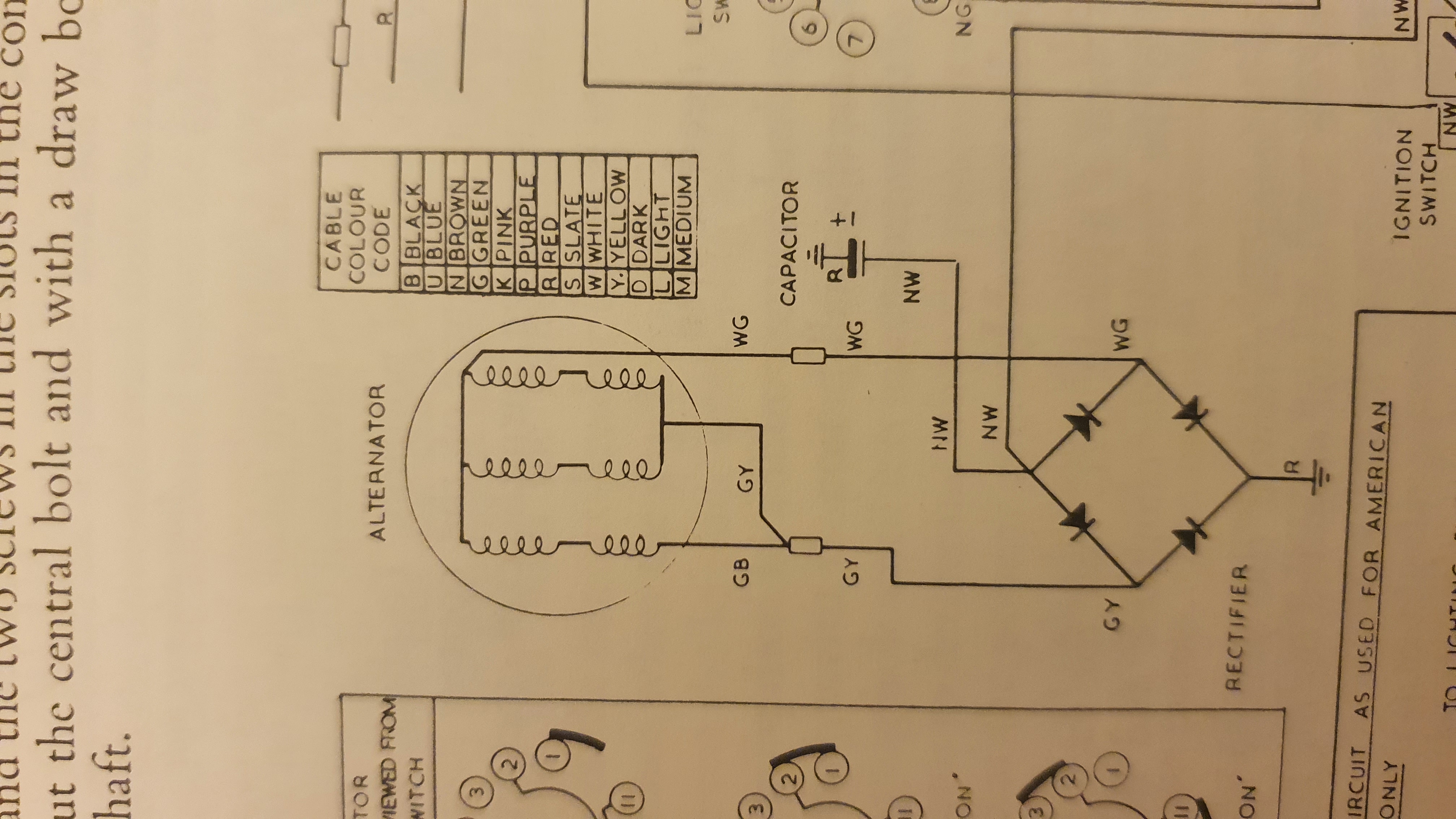
This extract from one of the…
This extract from one of the wiring diagrams might help you to decide why some pairs chosen from three wires will have different resistances.
If your wire colours are the same (they did change), then if GB to WG has resistance "R", then GB to GY will have "R/3", and GY to WG will have "R/2".
But resistance from terminals to earth goes through the rectifier...which should be small or zero one way and large or infinite the other way, regardless of the rotor.
- Log in to post comments
you do NOT...
You do not have the rectifier in circuit when you are testing resistance of the stator. The figures you have are good enough to use the stator. If you want to check the output current of the stator then you use a Bridge Rectifier, not a regulator rectifier.
- Log in to post comments
Finally solved
Hullo all,
After a long delay, I have finally fixed the poor charging on my '61 ES2.
There was a problem with the stator, so I bought a new one.
The rotor, although holding its own weight on a spanner, wasn't holding strongly enough. I borrowed a known good one and found it required considerably more pull to get it off the spanner.
I bought a good one from our local club.
So now, it is charging sufficiently to ride with confidence during the day, and with side lights on. If headlights are needed in the day, sufficient revs are needed.
Thank you all for your help and suggestions.
- Log in to post comments
Magnetism
In all my antics, I (tried) to measure the magnetism of the old rotor.
My phone has a compass app which shows magnetism (in micro T(Tesla!) units).
I found that with the center of the rotor 11 cm from the edge of the phone, mT measured 160, 115, 158, 114, 161, 116 for the 6 segments. Three high, three low alternately.
I don't know how useful this is, if at all.
- Log in to post comments


What voltage are you running, 6 or 12V.