
The 7 inch front brake fitted on many Norton models up to around 1954 has always been found to be lacking power. I have started on the renovation of my one and discovered some possible reasons why it is so! With a few easy mods I think I can get the brake working better. If anyone is interested in discussing the ideas, let me know please. Ta
Les
Would a part of the mods i…
- Log in to post comments
Hi Les, Some remedies that…
Hi Les,
Some remedies that I can think of are:
_ bridgeing the brake shoe pivots (like the later back brake) to stiffen the assembly while braking;
- fitting oversize linings and turning them down just to run free in the drum, then removing very little gradually towards the point where the linings will touch the drum first when the brakes are applied. The aim is to have as much lining material to be in contact with the drum. When using standard brake linings you could add 1 mm thick metal plate to the flat points of the brake shoes, so there is less free movement when applying the brake;
- stiffening the brake backplate by welding on some metal strips to prevent distortion of the brake backplate;
- carefull centralizing the brake backplate when fitting it all back in the forks: before tightening the wheel axle nut, give the wheel a good swing and apply the brake a few times over, then keep it sqeezed firm while tightening the wheel nut.
After 20 years of riding my Mod. 7 it is getting a full looking over and the brakes are on my things-to-do list. When I have the brakes apart I will decide which road to go. I'd like to hear others experiences.
Bye, Arne
- Log in to post comments
Hi Albert thanks for getti…
Hi Albert thanks for getting in touch. I have to say that all your improvements will work to some degree, but none adress the fundamental design flaws (2x) that this design has (In my opinion that is). It requires a long write up to go through what is wrong and how there could be some ways to remedy it. It will take a few days for me to get it put together soI did not want to wear out my typing pinkies for nothing.The proof will be in the eating so to speak, but it's nice to understand why the brake performs poorly (many road tests and users say so) and I think I can see why. I'm quite happy to be shot down if I'm wrongespecially if anyreplies are constructive,but I'll have my coat close by. I will be very disappointed if no improvement can be achieved as I have an interest in getting my one to work better too. Knowing that I have at least one receptivereader (you, hopefully) I'll put in on paper, so to speak.
Thanks again
CUL8TA
Les
- Log in to post comments
Hi Arne thanks also for ge…
Hi Arne thanks also for getting back, I was just about to shut down for today, so as you can see by my reply to Albert. I'll have some words on it in a few days.
ATB2U2
Les
- Log in to post comments
Previously wrote: The 7 in…
Previously wrote:
The 7 inch front brake fitted on many Norton models up to around 1954 has always been found to be lacking power. I have started on the renovation of my one and discovered some possible reasons why it is so! With a few easy mods I think I can get the brake working better. If anyone is interested in discussing the ideas, let me know please. Ta
Les
hello Les Are these the rear brakes then you are on about then Les As in 1954 Norton Went to 8inch Front Brakes your model must be early-er ? Your Anna J
- Log in to post comments
The following observations…
The following observations are taken from my own 1953 7" front brake plate from a Norton Model 7:-
The brake plate is in excellent original condition and as such shows little wear on any of the moving parts. As far as I know, the design of this brake is similar to previous 7" Norton single leading shoe brakes. The brake design is completely symmetrical in that the brake shoes are identical and each has their own pivot spindle and with cross-connected springs top and bottom of the brake shoes the operating cam has a nice elliptical profile which will give presumably a linear expansion of the shoes for any given angular movement of the cam, unlike some designs that have a flat cam with simply rounded ends.
My first surprising observation was that the centre hole in the brake plate is a tight fit on the wheel spindle, thus not allowing any shift or sideways movement of the brake plate in relation to the spindle. The normal task of centralising the brakes by applying pressure to the front brake lever and then clamping the spindle tightly against the forks to lock in that position, becomes a worthless exercise. All that happens is that one may feel that they have centralised the brakes but in reality no change has been affected whatsoever. The remedy is obvious and all that is required is for the central hole in the plate to be enlarged to allow the plate to shift from its concentric position to allow for any discrepancies in brake shoe contact, mostly caused by a different amount of wear on each lining. How much to enlarge the hole has to be carefully considered as the brake plate overlaps and rounds over the edge of the brake drum and any large offset, if created by the aligning technique, must not cause the edge of the brake plate to contact the edge of the drum. A 2mm increase in hole diameter with allow a + or â 1mm either way movement. This will be a good start and allow the brake to operate with immediate maximum performance but it will be short lived as there is a further more complicated design failing that has to be addressed.
The symmetrical cam profile, you might imagine, moves the shoes at an identical expansion rate. This is not true however, as the contact point on the shoe pressure end- pads are contacted at different ends of the cam. The outer tip pushes the leading shoe and the inner tip pushes the trailing shoe. I have carefully measured the difference using the actual witness marks created in the steel pressure pads on the shoes, it amounts to 17mm. The difference has the effect that the trailing shoe is moved a greater amount than the leading shoe for any given amount of cam rotation, causing it to contact the drum first. You might think that it wonât matter now that you can centralize the brakes and even if you didnât, the trailing shoe lining will eventually bed down to allow the leading shoe to make contact? Well yes that is true but there is more to it and Iâll explain later There is still another problem.
If we now imagine the brake set-up with identical thicknesses of the brake linings, and we have accurately centralized the brake shoes in relation to the drum, turning the cam will bring both sides and surfaces of the linings to contact the drum at exactly the same point of rotation of the cam. At this point we need to remember that the leading shoe, because of the âservo actionâ will, on contact with the drum, be pulled against the drum more firmly compared to the trailing shoe, which tends to resist the applied pressure to it, pushing back against the applied force. This powerful servo action of the leading shoe explains why it creates the greater braking force and also explains why the leading shoe brake lining wears down more quickly (when the brake is operating correctly). So when the brake is applied to slow the bike, the first application will see the lining of the leading shoe wear very slightly more than the trailing side as I have just explained, so it will now be fractionally thinner. I know it wonât be much initially but the effect will always occur at every application so the wear difference will gradually build up. Now we have to remember that the cam can only rotate until the linings meet the drum face, in fact it will be stopped even if just one of them does, and if this occurs it will leave the other side not quite in contact with the drum as further rotation of the cam has now become impossible. In the case of the single leading shoe brake, the thinner lining will always be the leading shoe and therefore the trailing shoe is the one that dictates the stopping point of the cam. In practice, there is a certain amount of flexing but as the cam spindle is such a good tight fit in its bush it does not amount to much. You can now see that the important leading shoe is very quickly from new, always slightly short of available cam pressure as it is always playing catch-up to the slow wearing trailing shoe and not receiving the same pressure caused by the restricted cam rotation.
What is needed then is an arrangement for the cam to always allow a balanced maximum pressure to be applied to both shoes and not have this force compromised by the trailing shoe. The most obvious way is to allow the cam to âfloatâ and compensate automatically. With hydraulic systems, this is easy, as a double ended ram will do just that. With a mechanical cam, we can have it move within a slot or at least allow some slop or slackness in its spindle. Iâll come back to this idea later as there might be other ways to overcome the problem.
If we analyse the situation, it could be seen that it is the different wear rates of the linings that are causing the leading shoes performance to be hindered. If both sides could be made to contact the drum simultaneously for the entire life of the linings, all would be well. One way would be to have a trailing shoe fitted with a softer lining and would thus wear faster and would match the higher wear rate of the leading shoe. This should be possible and with careful selection of material types, a close match of wear rates could be achieved. Another way would be to use similar linings but a length of the lining could be filed down in relief at the cam end of the trailing shoe to stop it contacting the drum. By doing so, the force on the remaining part of the trailing shoe will have the force on it magnified by the fact that the first point of contact on the drum will now be closer to the fulcrum point and will thus have an increased pressure on it, as well as having the same pressure applied to a smaller lining area. This should achieve a higher wear rate on the remaining part of the lining and with careful experimentation a close tracking of the wear rates might be obtained. One might argue that this method is removing good friction material but the increase in pressure will probably compensate, the higher wear rate is now to our advantage. Incidentally brake linings are always renewed as a pair and the leading shoe normally dictates the renewal point, the less worn trailing shoe is still discarded, so this method will not shorten the brake linings service life.
Coming back to the floating cam idea, one could experiment by enlarging the cam spindle bush somewhat. I would imagine that something like 1mm clearance would allow at least a period of service before the now âfloating camâ ran out of movement. One could obviously experiment with a larger clearance, the bush is easily replaceable if things did not work out I do not think that the spindle would rattle since the pressure of the return springs against shoe ends and the pull against brake cable will hold the spindle steady in its chosen location. Combined with the central brake plate hole enlargement a and with the routine centralisation, which can now be achieved, it should ensure that the full effectiveness of the brake can be maintained throughout the service life of the linings.
Oh yes, there is one more thing. You might remember that earlier I described the unsymmetrical cam action on the brake pad ends? Well it just so happens that the way it occurs in the Norton brake is unfortunately the wrong way round. Here is why;
As I have described, the wear on the leading shoe, (when it gets the chance to make good pressure contact) is always greater than the trailing shoe. You can see then that one could have a cam profile that just gives a touch more movement to the leading shoe side to compensate and not let the trailing shoe dictate the cam rotation. In fact we do get a similar asymmetrical action with the standard cam. It is caused by the fact the contact tips actuate the shoes with a different levering length of 17mm. Unfortunatelyâ?..the Norton brake has it the wrong way round! The inner cam tip is on the trailing shoe which because of the shorter lever length in relation to the pivot position, creating a faster (bigger) outward movement of the shoe compared to the leading shoes action.
If the rotation of the cam was in the opposite direction, the faster, longer movement created by the cam on itâs inner tip would be dealt out to the leading shoe where itâs benefits would be worthwhile. It is true that the leverage power of the two ends of the cam tips are also different, but once again in my opinion the greater power is required on the trailing side rather than have a bigger expansion movement, the leading shoe obviously requires pressure and the higher the better, but the problem here is that it is always struggling to get any decent pressure as the trailing shoe is restricting it.
So now I will list the stages of potential improvements.
1) Enlarge the brake plate hole.
2) Try to get a softer lining on the trailing shoe side. OR experiment with some contact reduction on the trailing shoe.
3) Ease off the cam spindle fit in itâs bush to allow some amount of float.
4) Modify the cam so the leading shoe side is moved fractionally more than the trailing side or visa versa.
5) Change the rotation direction of the standard cam by reversing the lever. It will require a new cable anchor on the front side of the drum.
Please note: these are ONLY SUGGESTIONS and IDEAS for thought, based on how I see things, every one of them could be WRONG, but then again some of them might be correct and result in an improved brake. The improvements are to viewed as a basis for experiment only. I would think it would be better to use an old scrap brake plate as not to ruin a good one. I have not as yet tried any off them myself as I have only started on my brakeâs renovation. I will certainly enlarge the brake plate centrehole and loosen off the cam spindle a little. Further changes will have to wait until I get the bike on the road and then I can judge how far I need to go to have a brake that I find acceptably powerful.
I hope you have found some of this interesting. I welcome any constructive comments, views or corrections regarding what I have written here.
Les
- Log in to post comments
Hello Les, Perhaps alterin…
Hello Les,
Perhaps altering the brake shoe pivot from a stout pin to a flat surface that is angled in a manner similar to the late 1968-70 BSA/Triumph 8" TLS front brake, would allow the shoes to self center without resorting to enlarging the brake cam pivot hole or the axle hole in the backing plate. when I sent my commando 8" TLS backing plate assembly up to Vintage Brake in Sonora CA. to get relined and fine tuned, I was told to slip a bush into the axle hole to reduce the semi-floating effect that the standard set attempted by having the axle hole a bit loose.
Admittedly I reverted to the SLS brake set up on my 19s as the TLS set up had racing linings, and while the braking was brilliant at speed, it was the entering my driveway speeds that were scary, the brake was very aggressive and really bit down hard at low speeds, I just couldn't see how dropping the bike would be any fun.
I have been told that the '68-'70 BSA/Tri front brake was one of the best of its day because of the floating shoe set up, I suppose you just might know someone who has one for you to examine. Just thought I'd pass that along
Regards,
Albert
- Log in to post comments
Hi Albert thanks for comin…
Hi Albert thanks for coming back with some ideas and thanks for reading my suggestions too. I'm interested in the flat pivot pin idea. I did consider the idea of getting the pivot end of the shoe to float. I would imagine that it would only be the trailing shoe side that would benefit although when I say "only" thatwouldstill beextremely worthwhile. Yes, the leading shoe pivot end is pushed hard against its pivotso would not get any benefit fromits pivot having a slack fit. However I can see that the trailing show, with a slack-fit pivot would allow that end of the shoe to pull away slightly by self servo action and make an attempt at giving some extra braking forcemore closely matched to the amount created by theleading shoe. Yes this is a possibility; I'll search more into that idea.
As far as your 2LS Commando brake goes. It does NOT require a loose fit on the spindle hole.Since both shoes are leading shoes, once it is set up by careful adjustment of the tie rod, the wear on each side should be identical, and therefore the mis-tracking that restricts the leading shoe with the Norton single leading shoe brake is not manifest here. You must remember, (and I'm sure you do realise but others may not)that the loose fit of the spindle hole is noteffective at creatingreal- time-working, self compensation, as the brake plate is clamped up rigidly when the axle spindle is tightened up, it is only there to allowperiodic manual compensation adjustmentsfor dissimilar wear rates for SLS style brakes.Currently the original tight fitting spindle does notallow for this basic adjustment.
So thanks once again for your suggestions. I'm amazed that someone has never systematically made a step by step experimental approach to improving the brake. Yes the 7" brake is somewhat small, but as it is, it is not giving its best for the reasons I have shown. POI:later 8" alloy brakes had the spindle hole enlarged, presumably when the "penny dropped" but then again as far as I can see, it still does not have a mechanism to deal withits lack of ability to let the leading show do its full qota of work as the cam is still trailing shoe restricted. Achieving "self compensation" willrelease the brakes full working power for the life of itslinings.
Since my long descriptive post, I have had further thoughts on the trailing show brake lining mod. It struck me that another form of lining removal could be better implemented by remove or relaxing down a centre part of it, say 1/4"central strip from one end to the other leaving the full length of the lining remainingeach side of the removed area. The increase in pressure thus created, should cause the lining to wear faster and match the all important leading show lining. This could be experimented on with a set of old shoes, negating the need to spoil new ones as long as they were not worn down to the rivets.
Best regards
Les
- Log in to post comments
Hi Les, It just occurred t…
Hi Les,
It just occurred to me that taking a look at Colin Seeley's double sided, drum front brake might be informative. It was an SLS brake when all other big, double sided drum front brakes were generally TLS, back in the days prior to disc brakes taking over the world. Admittedly it is larger than even the 8" Manx TLS front brake, if Colin Seeley felt it was adequate, it merits a look.
Regards,
Albert
- Log in to post comments
Thanks for putting these t…
Thanks for putting these thoughts together Les. I'll be interested to read how the improvements work. The idea of engineering in more slop rather goes against my ingrained assumptions but it makes sense.
I assume that the brake in question is fundamentally the same as that fitted to the late pre-war singles ? If so, bearing in mind your observations on the cam operation then I wonder if Nortons may have shot themselves in the foot for the 1939 model year.
Prior to 1939, the brake was mounted on the left with the lever acting to the rear. For 1939, they swapped the assembly to the right and the lever, instead of pointing forwards was once again rear-facing. There was a change of part number for the brake plate, reflecting the repositioned stay and speedo drive but all other components, including shoes and cams remained unaltered. The front brake remained on the right post-war and went onto the twins on that side.
Interestingly, the 1939 brochure stated "On all models the front brake is now mounted on the offside of the machine. This gives improved controlability, as well as providing a more direct speedometer drive."
By "controlability", did they mean less tendency to lock up ?
If there was a reduction in braking efficiency for 1939 then it must have been a small one as the left-hand brake is not a terribly sharp stopper either. This could though be connected with the bolt-up drum which apparently can usefully be replaced by a rear unit as the extra strength provided by the sprocket flange reduces flexing. (Speedo drive becomes unusable though).
- Log in to post comments
Hi Richard. Thanks for rea…
Hi Richard. Thanks for reading through and coming back with some details and thoughts and it is of interest that the different cam rotation of the post â39 models was thought to alter the brake characteristic toan extent that Norton made comment on it. I have noticed the Velocette Viper and Venom brake, always highly praised, had an anticlockwise cam rotation giving a slightly faster opening action to the leading shoe. However apart from diameter increases of 1 inch to 8 inches and some brakes having lining width increases of ?â to 1 ? â most British SLS brakes were very similar (Ariel alloy type had pivot adjusters to take up slack)
The aspect that puzzles me most is the lack of self equalising pressure that a fixed cam can provide. When an SLS type brake is operated with hydraulics as most cars had and still do on the rear of light cars today, it is very apparent on examination, that the wear on the leading shoe is nearly 1.5 to 2.0 times greater than the trailing shoe, showing that with identical pressure (Self equalising hydraulic mechanism) the leading shoe creates far greater pressure with the servo action and thus works very efficiently. Examination of cam operated motorcycle brake linings quite often show hardly any difference in wear rate between the two sides and thus gives an indication that the leading shoes attempt to work efficiently is being thwarted somewhat as I described. It seams odd then that all British motorcycles donât appear to have addressed this limitation. A fully floating cam would not have been that difficult to engineer.
It makes me wonder if the heavy feel of the brake (âconsiderable pressure was requiredââ?road test) is further evidence that the cam is being restricted by the trailing shoe which in effect is pushing against you as much as you push against it, leaving the leading shoe sitting there, in effect âyawning âand waiting for some movement and pressure. You can imagine that if the brake was set up with the trailing shoe set further back, applying pressure to the leading shoe only, would give a much different feel; a more springy lighter feel with more feedback as the shoe was âsuckedâ into the brake drum and responded more and more as the pressure was applied, causing it to bite harder and harder in relation to increased hand pressureâ?. well that how I picture it.
An experiment on the cam rotation could be an easy experiment to conduct, using an old brake plate pre-drilled and fitted with an extra forward position cable lug. Immediate comparisons could be made by swapping over the cable from one position to the other (brake lever will need reversing too). It would be interesting to see if any improvement or difference could be reliably measured.
As it is, without drastically modifying the plate (it is easier to fit the 8âversion, but then again departs from the originality of the machine) there is not much that can be done. I will loosen off the fit of the cam spindle and the trailing shoe pivot spindle not by a massive amount, just several thou. should help. With the larger brake plate spindle hole clearance too, regular centralising adjustments should keep the brake working mostly at its most efficient capability. As said before this is some way off though. Just an extra: keeping the brake cable regularly oiled makes a huge difference to the power of any front brake.
Anyway, as I said at the start, just food for thought comment and experiment really.
Thanks to Albert as well for mentioning the Seeley brake.
Les
- Log in to post comments
Hi Les, Arne is talking ab…
Hi Les,
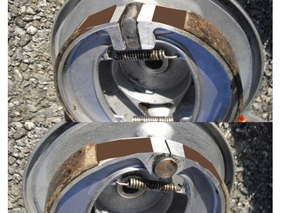
Arne is talking about thickness of the lining.
Did anybody try to change the length of them? Perhaps just on the leading shoe? What do you think about the idea?
Btw, does anybody knows about the original thickness of the linings when new?
Best regards,
Chris
Attachments
Brake-lining-length.jpg
- Log in to post comments
Very interesting thread wi…
Very interesting thread with some well thought out solutions to weak brake performance.
Concerning the issue of applying equal pressure on both linings, you mentioned the use of hydraulic activation through an automotive type of caliper. This mod was/is popular amongst AMC/Matchless/AJS owners, where a club member, modified the brake plate to take BMC/Mini wheel cylinders to activate the shoes. This of coursenecessitated a hydraulic lever, and hydraulic lines, which deviates somewhat from standard looks and setup, but still acceptable to most. Reports have been favourable on this mod, so might be worth taking into consideration.
- Log in to post comments
Do you think that some whi…
Do you think that some whizzo with a computer CAD program and a NC mill could make a brake cam with an asymetrical profile? Thus, equal pressure could be applied to the linings.
A lot of cognitive thought going on here. Makes my head hurt.
Mike
- Log in to post comments
I wonder why the 8" SLS br…
I wonder why the 8" SLS brake on my Dominator is so good whereas the 7" SLS brake on my BSA is so awful? Reading the above, I am surprised that the Domi brake can squeal the front tyre - surely the design is so poor it just shouldn't do that... One caveat with TLS brakes (as fitted to my wife's A10) is that if you apply the brake on a steep ramp, it won't hold and the whole plot sets off backwards. Not good!
- Log in to post comments
Previously wrote: Hi Les,…
Previously wrote:
Hi Les,
Some remedies that I can think of are:
_ bridgeing the brake shoe pivots (like the later back brake) to stiffen the assembly while braking;
- fitting oversize linings and turning them down just to run free in the drum, then removing very little gradually towards the point where the linings will touch the drum first when the brakes are applied. The aim is to have as much lining material to be in contact with the drum. When using standard brake linings you could add 1 mm thick metal plate to the flat points of the brake shoes, so there is less free movement when applying the brake;
- stiffening the brake backplate by welding on some metal strips to prevent distortion of the brake backplate;
- carefull centralizing the brake backplate when fitting it all back in the forks: before tightening the wheel axle nut, give the wheel a good swing and apply the brake a few times over, then keep it sqeezed firm while tightening the wheel nut.
After 20 years of riding my Mod. 7 it is getting a full looking over and the brakes are on my things-to-do list. When I have the brakes apart I will decide which road to go. I'd like to hear others experiences.
Bye, Arne
- Log in to post comments
Hi, I recently had Dave De…
Hi, I recently had Dave Degens fit a 1968 8 inch tls from a T120 to my 1960 Model 99 with fantastic results. The bike can now be ridden in modern day traffic quickly but more importantly safely. He recommended this conversion as the 68 brake was the best production brake made. He modifies the back plate and the hub,not the fork leg so the assembly fits perfectly and looks like a factory fitment. Not cheap but this outperforms anything you can buy nowadays and looks far better than the rather bulky looking Norton 2ls derivatives. AndTriumph also made a 7 inch versionsuitable for older models. Chris.
- Log in to post comments
Hi- Very interesting threa…
Hi- Very interesting thread and I think I've learned a bit already. Sorry to divert things a bit but as everyone here seems very knowledgeable (at least more knowledgeable than me ! ) perhaps someone could answer a question that I've been pondering - Does it make any significant difference if the brake drum is turned before lacing the rim as opposed to after? Questions of swing over the lathe bed aside , I would think that there would be some distortion of the drum from spoke tension. I'm about to embark on building a TLS brake and have a small lathe but not big enough to accommodate a laced wheel. Any thoughts? Thanks to a in advance for any thoughts on this-Richard
- Log in to post comments
when a rim is laced it can…
when a rim is laced it can pull the hub out of true
- Log in to post comments
Time maybe to revive this…
Time maybe to revive this thread? It seems to cover most of the ground.On other sites there are those who say that removing several inches from the trailing end of the trailing shoe reduced the tendency for it to be held off by servo action, and increases wear on the trailing shoe and thus allows the leading shoe to work harder all the time.I understand the big attraction with disc brakes is the complete lack of servo action since servo action of TLS brakes can be unpredictable. My TLS on the Dommie is dangerous when first used after a long lay-off.
- Log in to post comments
RGM sell a small stiffener…
RGM sell a small stiffener for the rear brake which is intended for a Commando but apparently can be used on Dominators as well. Plan B is to buy one of the thicker alloy rear plates available from various sources.
Attachments
rear-brake-torque-stay-jpg
- Log in to post comments


Would a part of the mods involve lengthening the operating lever by an inch or so, or perhaps internally stiffening the backing plate? I think Norvil offers longer operating levers for both the 8 inch SLS and TLS brake. I suppose increasing the mechanical advantage would help, that and upgrading the lining to one that resists heat and fade better.
Perhaps a stiffener similar to the one for the 8 inch TLS brake could be made up and slipped into place, it would anchor the pivot ends and not offend the purists by being seen.
Enjoy your project,
Albert