
A brief word to those already initiated and wise... If you want to get to the sole purpose of this thread, please skip to the bottom of this missive to the last two short paragraphs followed by my questions so as to save yourself time and relieve yourself of the burden of my attempts at humor...
Otherwise... Forewarned is forearmed. I cannot resist sharing my curiosity aloud any longer. And I want to try to have fun with this topic by exhibiting some sense of humor around this subject that's so well shocking me...
I've recognized and accepted and am immersing myself in the rich history by which many International machines have become a mix of parts resulting from their storied and illustrious racing careers, the joys and sorrows the International has given the countless many before us and the ravages of time that can exact its cruel toll on our beloved 80+ year old motorcycles. In fact, I am looking forward to learning with a somewhat morbid curiosity what Chris Streather's certification will reveal and what more questions I will have from engine and frame numbers I've submitted that may offer some information offering some more clues about my International. (My "morbid curiosity" rises from having practiced as a registered nurse for 48 years).
When I purchased my International, the seller warned me that "It is a fact of life that International's leak oil." I have to admit that I am in a state of gobstruck awe of the amount of oil my '37 leaks seemingly from any and every joint and opening that the engine and gearbox have. (That's a slight bit of an exaggeration, but not far off from the truth, and please remember I am trying to put what humor I have to its best use).
My International puts my '67 R.E. Interceptor (also affectionately known by some as the Royal Oilfield) to shame for the amount of oil that's leaking out of my International. I remember as a youngster, when Japanese bikes were well into making their debut hearing from old timers how they didn't leak oil like British motorcycles. My first British bike when I was 17, being a '67 BSA Lightning, the little amount of oil that it leaked made me doubt the veracity of these old timer's comments. And my '74 Commando I bought new in in April 1974, leaked no oil (nor does the '74 i restored leak oil) so the old timers had to be exaggerating. Both of my 1927 H-D JD's that I've built literally leak a mere drop or two regardless of the number of miles they are ran or how long they sit. I thought I had a pretty sturdy constitution when it comes to motorcycles leaking oil, but my Inter has raised the bar and is shivering me timbers, matey's... When a well-intended Norton Facebook member told me to wear black pants when I ride my International, I thought... "Yaah." "Right..." "That's only an affectionate exaggeration on your part in a cheerful attempt to humor me..." "Good for you to wear black trousers, not me..." Thankfully, I've been wearing black jeans for decades and have several pair on hand. Forewarned is indeed forearmed. Having owned a number of British pre-unit singles in my earlier life did not prepare me for my present day International ownership. I expected to see some oil leakage from places International's are known to leak, but not the amount that seemingly rivals the blowout of an oil well.... https://www.youtube.com/watch?v=VGoKmemlfoo&ab_channel=MikeVickers
To those who skipped to here, please read the following... (:
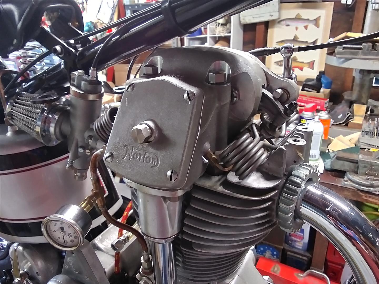
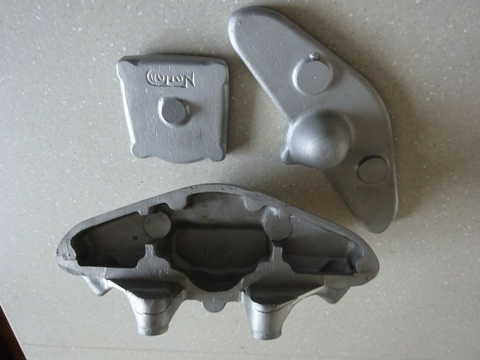
The most distressing leaks are at the bottom and top of the bevel drive housings and the vertical shaft tube itself. I literally can watch the oil slowly seep out from those joints. Earlier this evening, having read here in "Models" that the International "...sadly received virtually no development beyond 1936." (and) "Nothing was done to improve its poor reputation for oil leaks either; owners had to seek their own remedy." Ouch! Having read this in our club site, I am more of a believer and still somewhat of a skeptic that an International should leak oil as well as mine does. Since my 3 mile test ride Sunday last, I have been hearing sounds from my curious self such as, "Huh..." "Hmm..." "Huh..."
Looking in my '37 and '46 Spare Parts Lists, having always thought that this Yank was pretty clever interpreting the intended meaning from descriptions made in the British vernacular, right about now, I'm feeling quite humbled. In the both Spares Lists I see the terms such as "packing washer," "housing washer," "paper washer," and "cover washer."
Are some of these "washers" metal shims and others paper gaskets? I fear to deduce; therefore I humbly defer to your experience and wisdom.
Might these upper and lower housings have paper gaskets fitted? And/or a metal shim aka "washer?" (I ask this because I note in the '46 Spares Lists there are 2 items depicted appearing as perhaps a paper gasket or metal shim for the housings and only one of these items is given a number to reference the part number and description of the part).
Does the top and bottom "rubber ring" for the vertical shaft tube perform its intended use well? (As it is, beautiful golden oil runs down the tube like a rivulet formed from melting snow in the warmth of springtime sun).
All jocularity aside, where should the Inter engine not leak from?
Or... Are these leaks another one of the features of International ownership that I shall endear and adjust myself to? If so, then no big deal, I shall do it! (I'm too dumb to give up so easily).
I have a couple of exotic…
- Log in to post comments
I'd appreciate a good…
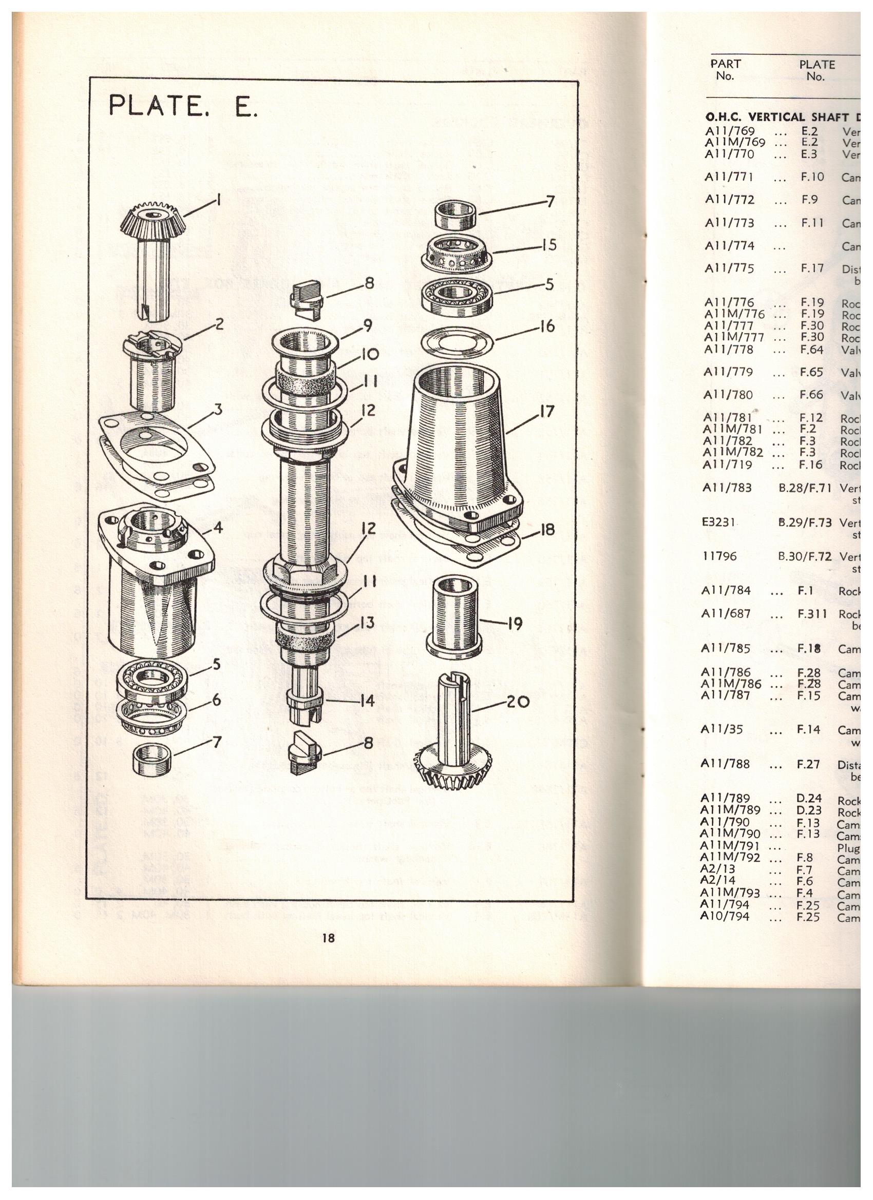
I'd appreciate a good engineering drawing showing exactly how the vertical shaft goes together. The copper crush washers only act as a barrier between the flange surfaces. I put a smear of Wellseal on mine, but I don't overdo sealants. Inside are rubber collars. Nowadays I would expect to fit lip seals or x-rings or even o-rings. One of our suppliers sells replacements for the fittings which allegedly solve the issue once and for all. Does anyone have experience they can relate?
The oil tell tale was fitted by Norton on all their bikes when the full dry sump recirculation system arrived in about 1930 (or 29?). Prior to that riders were used to being able to watch the drip feed in progress, so the indicator must have been considered a good idea. But they also leak past a leather washer, and later designs like the Dommie don't have them.
Rockers famously splash. Quite a lot comes out along the sides, and the washers were changed a couple of times.
I hope there will shortly be more expert contributions. Spring is just trying to arrive here, so my leaks will stay as they are for the time being. But I am toying with the idea of fitting o-rings outside the rubber rings. Surface contact pressure on a ring about 3/4" long must be too low to provide a seal.
- Log in to post comments
Reply to David, "I'd appreciate a good…"
Seeing an engineering drawing would be great!
I hope we can learn more about, "One of our suppliers sells replacements for the fittings which allegedly solve the issue once and for all. Does anyone have experience they can relate?"
As do I, "...hope there will shortly be more expert contributions."
I'm very interested in hearing more in your "...toying with the idea of fitting o-rings outside the rubber rings. Surface contact pressure on a ring about 3/4" long must be too low to provide a seal."
Double ditto, "Spring is just trying to arrive here, so my leaks will stay as they are for the time being."
- Log in to post comments
Sales talk?
>the seller warned me that "It is a fact of life that International's leak oil." <
Mmm, seems to me that the vendor was trying to pre-empt any post-sales comeback for a less than perfectly assembled machine, just in case the disobliging buyer actually intended misusing the bike by riding it, rather than adopting the now widely-accepted 'proper' approach to ownership of such impressive engineering; ie much polishing before trailering to various display locations, in which case there's absolutely no need to fill it up with oil anyway!
- Log in to post comments
They don’t leak...
...they were just never closed. The valve gear was always external and meant to be wet. The other leaks you mention are controllable far better than your example but they are a tad weepy around the vertical. I sense a lack of local availability for the general seal providing items for the Norton. Your leak will require a reasonably major disassembly, to the point that if you feel the general assembly is weepy it may warrant a motor out disassembly to cure. Ride it, clean it, ride it, repeat... to determine the extent of your problem. One small leak appears to be a food but one pinched rubber or trapped gasket with the expected flow adds up to a blow out! Run the bike short durations to spot he source, talc around the joints to spot exact locations.
Unfortunately your shaft problem makes it difficult to assess the overall picture, but to correct it, assuming the nuts are tight, is a bit of work. Does the oil leak whilst on the run or pool there after a run?
Make sure your oil flow down the shaft is not inhibited, it’s the only way back down ( besides the outside route...), the filter bolt below the bottom bevel housing needs checking for blockage/debris.
Cambox off, minimum so then the cam wipers and adjusters need checking.ensure you have correct gaskets fitted to cover plates. Copper crushes are a one job use, must be replaced. Rubbers top and bottom must be change to get any chance of sealing.
Tell me what documents you need if you are going to tackle it.
You are correct about specific 1937 docs on this model. They seem to be 36 or 38. But engine wise, long stroke single cam is common to most years .
If you got internet phone and your on a compatible time zone we can have a chat about it.
cheers
Jon
- Log in to post comments
Reply to Jonathan, “They don’t leak…”
Agreed, “Ride it, clean it, ride it, repeat... to determine the extent of your problem.”
Acknowledging your comment, “Your leak will require a reasonably major disassembly.” Please review my post, “Remediating vertical shaft tube and bevel housing oil leaks.”
The oil leaks at upper and lower housings and vertical tube are visibly active while the engine is running. Those are the only leaks that I want to seriously concern myself with. At least in the not too distant future.
Will Do! That is, “Make sure your oil flow down the shaft is not inhibited, it’s the only way back down ( besides the outside route...), the filter bolt below the bottom bevel housing needs checking for blockage/debris.” Fwiw, I see oil actively recirculating in the oil tank when engine is running.
Your next comment likely requires a phone conversation at some future time... “Cambox off, minimum so then the cam wipers and adjusters need checking.ensure you have correct gaskets fitted to cover plates. Copper crushes are a one job use, must be replaced. Rubbers top and bottom must be change to get any chance of sealing. Tell me what documents you need if you are going to tackle it.”
Addressing your above comments:
- I need to look at the factory books to determine what “cam wipers” and “cam adjusters” are…?
- “…correct gaskets fitted to cover plates. ” What is a "cover plate" and what makes a gasket correct?
- Understood on one time use for copper crushes and top/bottom rubbers. Where can I source these spares? I will purchase in advance so I have them on hand when I tackle the project.
- “Tell me what documents you need…” Documents I already have are a 1946 Factory “Maintenance Manual and Instruction Book,” 1936 and 1938 "Maintenance and Instruction Manuals," 1946 “Spare Parts List,” 1937 “Spare Parts List” and “Building and Tuning the OHC Long Stroke Norton Engine,” 4th Edition compiled by Mitchell Barnes. I also have “The Vintage Motorcyclist’s Workshop” by Radco. What other documents will benefit me?
- My phone accepts international calls; I do not have service to place international calls. My time zone is Mountain Standard Time, assuming you are in England, then you are 6 hours ahead of me. Right now, where I am at, it is 4:22 pm; London time is 11:22 pm.
- Log in to post comments
Terminology corrections.
1. Cam wipers - I mean rocker wipers: rubber/canvas insert to top and bottom of rockets that seal the oil inside the cam box ( f45-A11/815). Compressed by inserting steel gib plate(f46- A11/846) under bottom one and adjust by square drive screws (f56- A11/817) and locked with the nut. I actually use the gib on tops as well to give good compression of the rubber.
2. Cover plate - Rocker box cover plate (f30- A11/777) and f2 inspection cover, these need to be handled very delicately, they are paper and the sealing width is very narrow. Very meticulous mating required.
3. You have mentioned usual suspects previously. Stu Rogers +441945585116 has everything you need. Not easy to get hold of but once you do he will prove a huge source of information. Paul Norman @ Racing Vincent usually has stuff but tends to be a little pricey. From your location you will not go wrong with NZ Ken Mackintosh, very easy to deal with.
4. You have a good set of docs there Mitchel Barnes is always good for information his book covers the work you are doing. EM Franks book of the Norton , generic Norton handbook but good balanced view on what’s needed.
5. We are on British Summer Time BST GMT+1 now so you MST should be 7 hrs separation. Do you have WhatsApp or other web based phone system? Send number in PM I will call you.
The shims set the mesh of the bevels but the built up length needs to ensure the Oldham couplings are not bound. As you can imagine the built up height of the motor varies on compression plates and spigot grind. It’s usual to gap the couplings without the tube installed then remove cam-box and rebuild. Couplings come in various sizes but wet grind a little here and there to give the clearance is ok. I run an alloy cylinder s not sure of the recommended clearance. I’m sure it’s in one of the books you have.
The bearings for the bevels are hard to get, and could have been replaced with others that restrict the oil flow. The amount you show coming out looks unusual as it’s an atmospheric assembly.
if you major source is not masking the cam-box leaks, leave it be. It’s the worst place point to exude oil if not built properly, so if it’s negligible in comparison .... leave it for now. Better to get miles on and determine what you have got under you.
Cheers
Jon
- Log in to post comments
Remediating vertical shaft tube and bevel housing oil leaks
Thank you all for your comments. The build quality of this machine does not equal my expectations based on the quality of restoration work that I do. I purchased this completed machine because I am well aware of the time and expense commitments involved making restorations right, and being in the 69th year of my life, I don’t want to be spending the next 5-10 years building a machine I might never get to ride. I’d be remiss to not admit some disappointment with the build quality of this machine. Moving on… I am the custodian of a most lovely International that I’ve wanted since my early 20’s.
Once I have eliminated the petrol drip from the carburetor, then I can ride the machine, familiarize myself as miles tick by, read the literature, ask questions; all part of what makes old bikes so enjoyable and rewarding. Based on my own experience with machines I’ve worked on, the amount of oil coming from the bevel drive is not what the manufacturer intended. Were it not for these leaks, the remainder would be part and parcel of ownership.
I am aware that my following thoughts and questions precede a more thorough study of the factory parts lists, workshop books and the rebuild guide by Mitchell Barnes. It’s not necessarily easy trying to visualize what parts look like, how they are intended to be fit together along with the steps and procedures allowing the build be done right so things don’t have to be disassembled a second time. Especially so when I’ve not seen these parts as they fit together except as depicted in spares and workshop books. I don’t doubt my mechanical abilities, but I want to be as informed as I can before I turn the first nut or bolt.
I will sincerely appreciate your comments to my general thoughts and questions to help me begin wrapping my head around remediating the bevel drive leaks when the time comes.
It seems there are essentially 4 leak sites, the top and bottom bevel housing leaks and the upper and lower rubber rings for the vertical shaft tube…? The cam box will have to come off to remediate the bevel drive oil leaks…?
- Am I of the correct understanding that the upper and lower bevel housings are fitted both with paper gaskets and copper “gaskets”? (I am not referring to the copper top and bottom “union washers” of the “vertical shaft tube”). (I see a part number for item numbers 3 and 18 being referred to as “housing” and “packing” washers respectively. There is another exact appearing "washer" with no reference in Spares List).
- Proper fitment of the vertical shaft rubber rings is critical to reduce leakage.
- I’m wondering if the copper plate and paper gasket top and bottom are certain thicknesses affecting deck height and in turn bevel drive gear lash? (I’d be cutting my own gaskets, so this may be a valid consideration).
- Bevel gear lash is adjusted by “packing shims” as per the factory shop manual? (Looking at spares and workshop manuals, I can’t seem to put my eyes on these shims).
- I would think a sealer such as Three Bond, Yamabond, Kawabond, etc, will help make the desired seal.
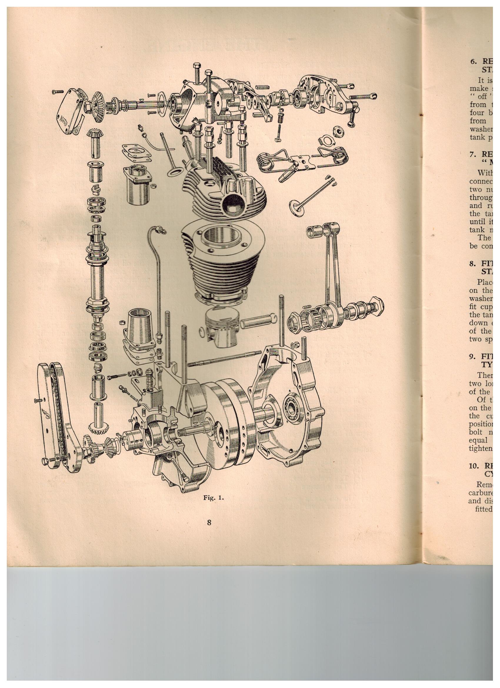
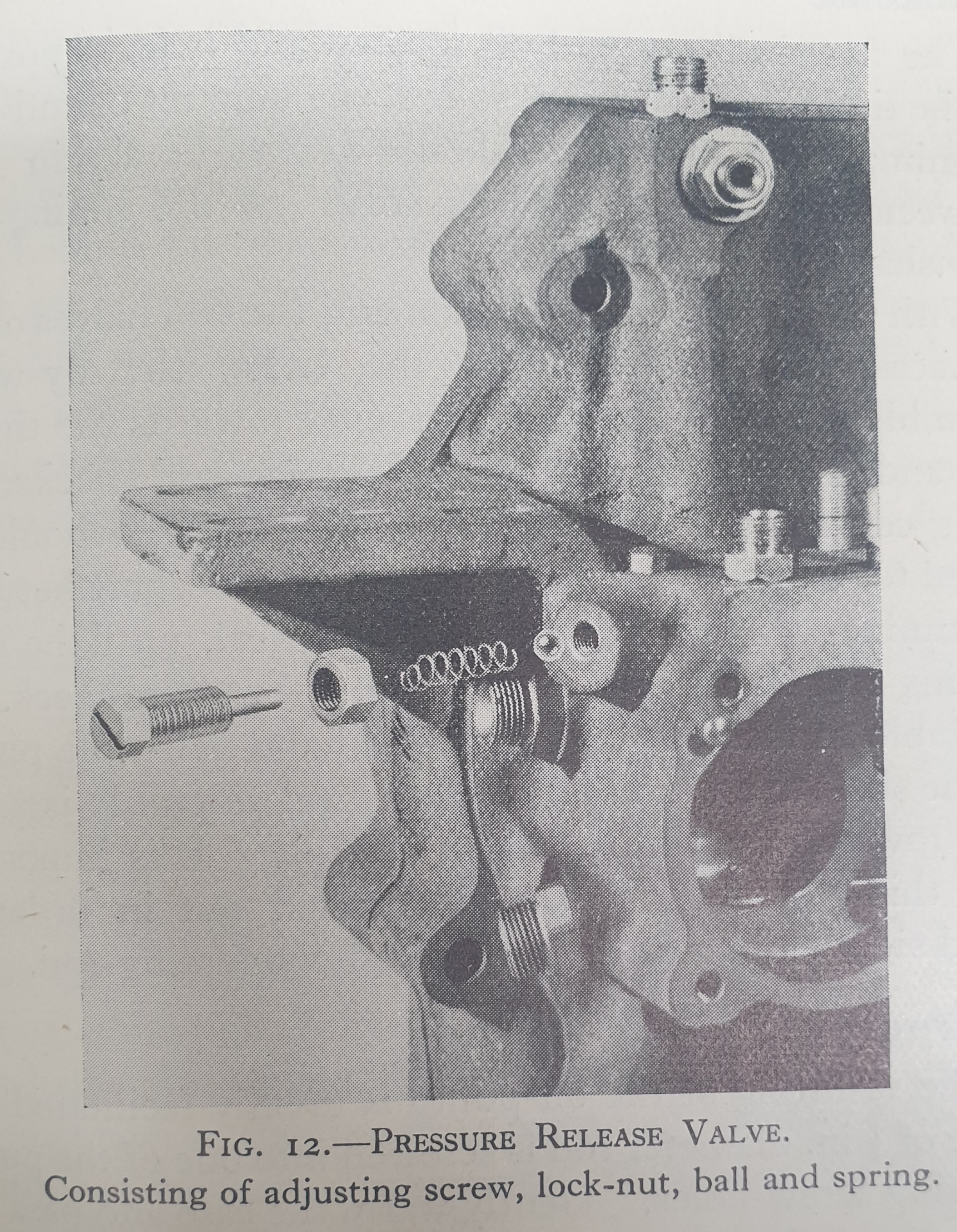
- Looking at the attached exploded drawing, it does appear the cam box stands alone, is fixed separately to the cylinder head without disturbing the cylinder head joint?
- I have a granite surface plate so any minor surfacing work required allowing at the least a somewhat better fit of upper and lower housings to the cam box and crankcase, I should be able to do.
- In the meanwhile, I’ll be reading the factory shop books and Barnes and asking you fine fellows more questions as time goes by.
I hope my thread will benefit fellow members. Enough for now; thank you for your participation in my journey with an International.
Kind regards to all; stay safe and stay well.
- Log in to post comments
I'm hoping this will stop my…
I'm hoping this will stop my leaks when completed.
- Log in to post comments
Dan...is that a copy of the…
Dan...is that a copy of the enclosed top end as used in 37? (or 38...)? It looks like the rockers and springs will be enclosed, but will it contain the tops of the valves? And will it use coils?
- Log in to post comments
Jon, let me digest...
...what you've written, let me do my readings and once i have a somewhat better understanding of what you've written, then we can schedule a time to get together on the phone... As with my other bikes, the International is no different in terms of my commitment to it, so it likely may be bit before i feel prepared for us to talk on the phone so as to not spend your time explaining things that i can better understand by doing some reading and research on my own, e.g., looking up pn's you provided for wipers and gib plates, etc. I also forgot to mention that I have EM Franks, so will refer to him in my preparatory readings before our phone call. As an aside, to help minimize confusion and for my own sanity, i always try to adhere to the vernacular seen in factory literature rather than naming or describing a part as something other than the vernacular seen in the Spares List and Maintenance Manual.
With the International, i know that i am on the front end of establishing a familiarity with the machine, so i really appreciate you for being willing to help me as i learn more abut what i want to understand. The last paragraph of your reply is very helpful to better understand considerations as i move forward.
Agreed, intend on put some miles on so i better understand what's under me.
Kind regards, Steve
- Log in to post comments
I read somewhere that excess…
I read somewhere that excess oil leaks from the cam drive can be caused by the omission or inefectiveness of the steel shim that lives beside the timing side main bearing . Put there to reduce the pumping effect from the piston it can be improved by the fitting of a sealed bearing . This memory only came to mind as I am dealing with a similar omission from a Big Ducati bevel motor where the omission of a simple pen steel washer re-routed the entire big end oil supply directly to the sump !.
- Log in to post comments
Thanks Robert, for your...
...comments. My oil leaks have to be a matter of the vertical tube and upper and lower housings' setup not done as well as it needs to be. I'm going to familiarize myself with the literature as far as all the parts related to sealing the bevel drive and the cam box are concerned, put some miles on the machine and once I've done so, then revisit the leaks with some of the folks here on the forum.
- Log in to post comments
There is also the…
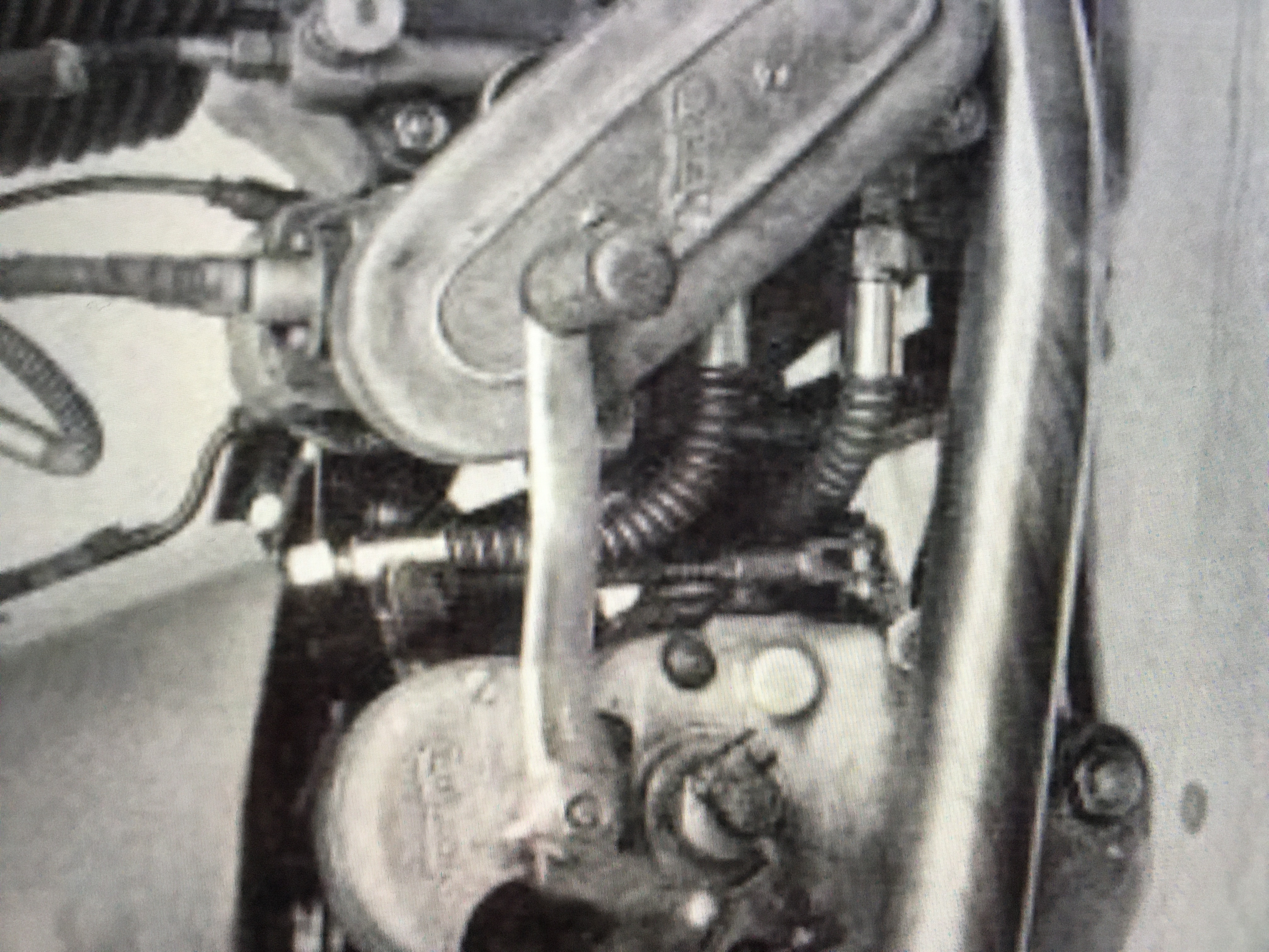
There is also the possibility of over oiling caused by too much pressure in the cam box oil feed pipe. Measuring it is on my "to do" list. There is an adjuster screw I've never touched.
- Log in to post comments
David, thank you for...
...coming back to this conversation, I always appreciate your observations and comments. I'm slowly coming up with a plan of approach for addressing these leaks which in my mind are not leaks which new engines would have when they left the factory.
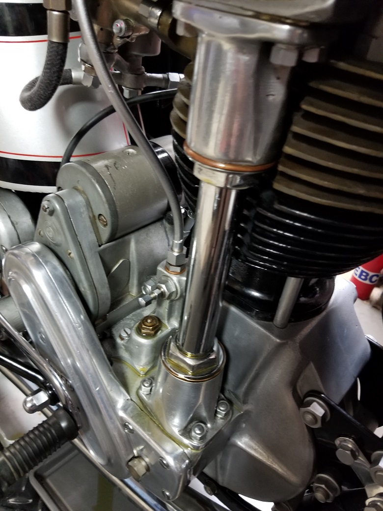
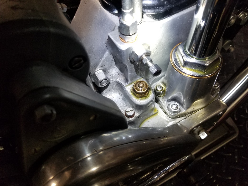
David, to clarify, the adjuster screw you are referring to is immediately above the “oil pump tell tale,” i.e,. the brass hexagonal devise (immediately to the left of lower bevel drive housing) that has a plunger in the middle of it that sticks up when engine is running; this adjuster (needle) screw being held captive by a nut, this is the adjuster screw you are referring to…? (photo attached).
First, i need to read the literature i have. Second, i need to ride the machine to get familiar with it. Third, i then need to have a reasonably defined step-by-step approach for a beginning point to address these leaks.
In my mind, the most concerning leaks (because they are SO ACTIVE) are at the upper and lower drive housings and the vertical shaft tube. As things are now, until I have done "1, 2 and 3" above, i really can't move forward. In my mind, it seems inevitable that the cam box needs to be removed so i can address leaks coming from the housings and the tube. I'm not going to start ripping things apart until i feel I've done my homework and ridden the machine a bit.
I appreciate folks comments, i'm just a bit concerned i many not move at a steady purposeful rate to plan an approach to remediate these leaks until later this summer or even into the fall, but i'll do what i can to keep this thread alive and moving forward.
Kind regards to all who participate here; i appreciate it very much.
- Log in to post comments
Just be thankful the PO didn…
Just be thankful the PO didn't fill it with castor oil!
Removing and replacing cam box isn't really all that problematical. It's not like re-shimming the entire engine from a box of bits. But as you say...I'd use it a bit first. Carry a soft cloth. You'll need it to wipe off the oil splashes from the rockers anyway.
The design was made to be accessible so valve springs stayed as cool as possible and, if they broke, they could be replaced at the side of the road. Some riders carry spare springs tied up tight with lock wire, ready to slip into place. They weren't intended to carry a blushing bride to church on the pillion.
- Log in to post comments
Oil feed adjusters.
Hi Steve,
The adjuster in your photo controls the rear cylinder oil feed. This only needs a small quantity so the adjuster should be screwed fully in and then turned back just half a turn and locked. The oil quantity to the cambox is controlled by the adjuster behind the timing chain casing and is difficult to get at with the casing fitted, best set during an engine rebuild. The correct way to set this is to remove the adjustment screw, spring and ball bearing, you might need a magnet and short rod to get it out. Clean and inspect these parts and make sure the ball bearing is not damaged. Re-fit the ball bearing and, if you can get at it, use a small drift and tap the ball in to place firmly to make sure it seats in the aluminium properly. Re-fit the spring making sure it is in good condition, and screw in the adjuster fully home, then turn back two and a half turns and lock. If you have a suitable oil pressure gauge you can fit to the cambox feed pipe, it should be 8 psi.
- Log in to post comments
Just be thankful the PO didn't fill it with castor oil...
...yeah, no S - -T. in the foolishness of youth, i ran castor oil in my B50. Sure smelled good.....
David, thanks for the comments on cam box removal not being problematic as it has crossed my mind that at least i am working with a running engine and not a box of parts of which i am quite familiar with on my '27 Harley builds.
Thanks again for your comments. It would be a long, lonely road without you guys!
- Log in to post comments
Hi Steve, Its clear that …
Hi Steve, Its clear that your machine has not had the benefit of " shakedown use", so you need to be keeping a wary eye on all parts !. From my own experience of runs on the 36 Rudge ,oil leaks of that magnitude are very wearing , if you get up to full working temps you will dissapear into a cloud of smoke everytime you stop. With regard to oil supply, there are 3 possibilities , 1 you are overoiled,2 you are getting the correct supply ,3 you are underoiled !, All are possible even with the signs that you are getting .
- Log in to post comments
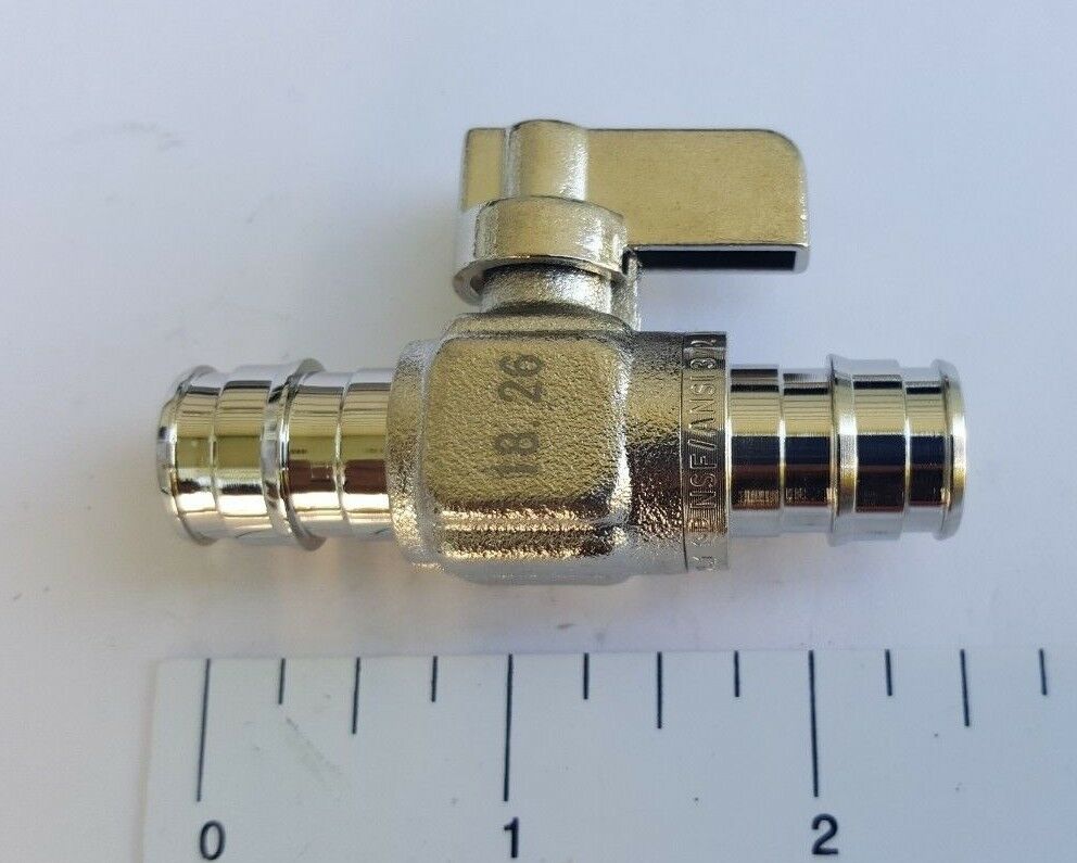
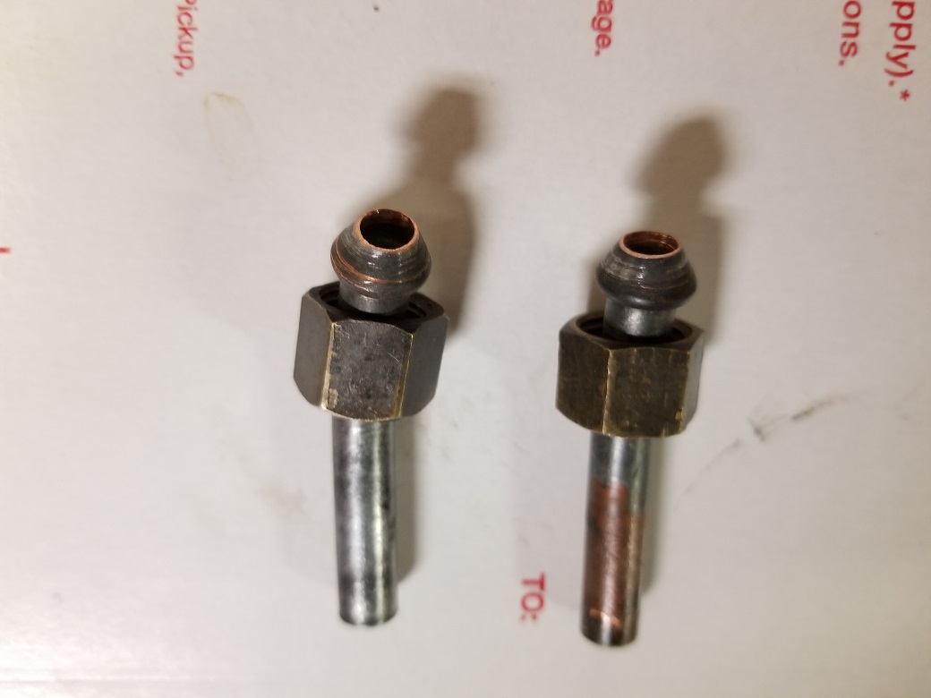
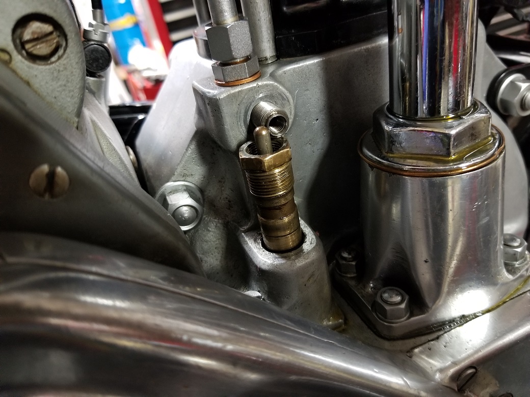
Where can I source this fitting?
I would appreciate if anyone can tell me where i might source at least one, preferably two of these oil line fittings so i can fit a compact ball valve inline.
The fitting in the picture is from my '37 International; 5/32" i.d. which is also the i.d. of the compact ball valve i intend to use. I've looked on the different sites i know of and have not seen this fitting.
As much as i don't want to fit an inline valve it's the practical thing to do otherwise i'm going to have to drain the oil after every ride so the oil in the tank does not dump into crankcase overnight. I want to log some miles on the bike to better familiarize myself with it. I could clamp the hose, but would prefer a valve in lieu of fiddling with a clamp.
Thanks in advance and kind regards.
- Log in to post comments
Hi Steve, If after you have…
Hi Steve, If after you have managed to stem the worst of leaks and got some running time in ,you are still unhappy with lubricating the enviroment please re-visit my comment of the 14th April . I have found that you can chase leaks all over , but excess air pressure (and oil!) will find a way out. In my case through the magneto on my 750 and through the distributor on the 99 which can leave you stranded . Not yet the time to get too deep into the motor ,but I see it in your stars !!.
- Log in to post comments
Thanks, Robert...
for referencing me back to your post of the 14 instant for which is part of other posts i have copied, pasted and printed off. Do you have any suggestions where i can find that fitting i posted here and above? I've looked at different sites and no seen anything.
- Log in to post comments
I'm mystified, but thats…
I'm mystified, but thats pretty normal , is that an Inter part ?. or something aftermarket.
- Log in to post comments
? 1/4BSP Flare...
... without the nut, the other end for a “push on” hose? Just get the right bore tap with its fittings to help you resolve the leaks. I take it you are draining the sump before each trip? Your level of spillage is extreme. As RT, Something is wrong or missing in the breathing of this motor...
Jon
- Log in to post comments
As Jonathan says...that is a…
As Jonathan says...that is a bsp pipe flare. There are several on the Inter. Two are on the ends of the flexible cam box oil feed pipe.
Paul Norman in his 'racingvincent' web site sells replacement housings for the oil seals at the top and bottom of the vertical cam shaft drive. He also provides links to various web pages with hints and tips on Inter engine assembly.
If the engine was properly assembled, you shouldn't have to worry about the various shims etc in the cam drive. Remove the cam box and take the tube out. Replace the cam box without the tube. Then you can check bevel backlash is present but not excessive. Also check the fit of the shaft top and bottom couplings.
If all is good, reassemble. New crush washers. I suspect the replacement upper and lower housings with proper o-rings will sort out the leaks. I carry an old towel.
Oil taps are always a risk. I have one because previous owner fitted it. I hang a big magnetic notice on the tank whenever the tap is closed. I never close it unless it is in the garage. There isn't much space for one, as you have found. Interlock switches are made including an earth cutout for the magneto for single cylinder bikes. See 'the magneto guys'.
As Robert says...sealant for minor oil leaks. I use Wellseal. Mucky stuff but does not set. It finally cured my carb banjo fitting fuel leak that has driven PO to distraction over the previous 10 years.
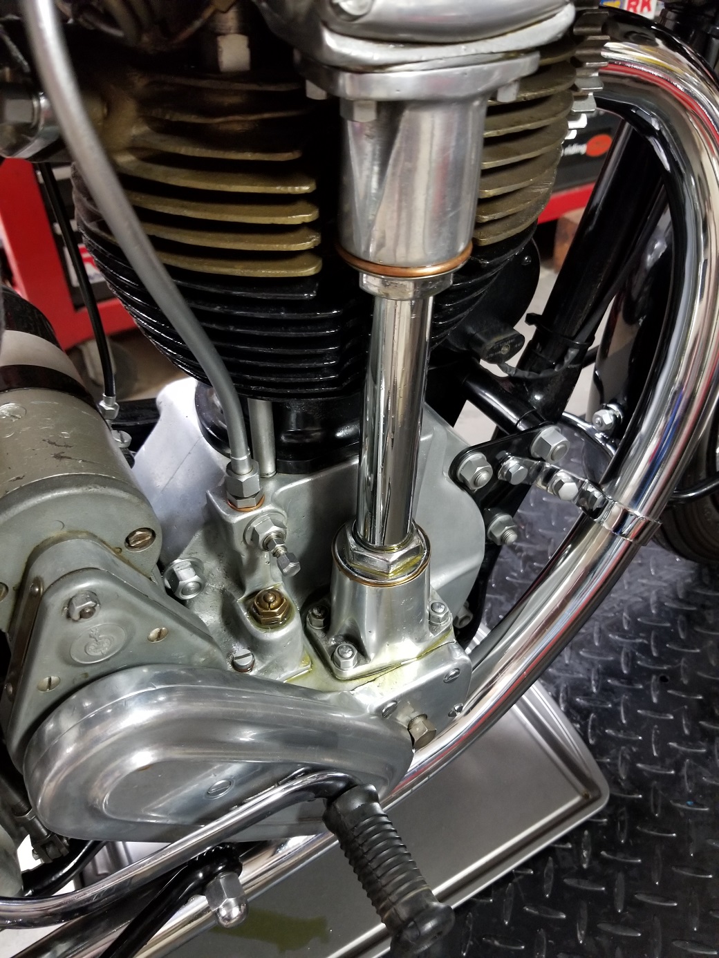
My engine has at least three breathers I know about. Some have more. One on the left behind the primary chain case, one on the right with exit pipe sticking up beside the cam drive housing and one on top of the oil tank. Later race bikes (30M?) have one on the front of the crank case. Norton seem to have a fetish about breathers...almost as has as the one about changing silencers every year.
But after all that...it goes like the proverbial bomb. Not as fast or comfortable as a Dommie, but feels exciting all the time.
- Log in to post comments
Thank you, gentlemen...
...Robert, Jonathan and David for your kind replies.
Robert, I don’t know but I have my doubt that ¼” BSP flare is an International part. The little amount I’ve done perusing parts books, looking on websites, my impression the feed and return lines are one piece…?? Also, your comment of the 15th instant did not go unnoticed. Obviously this engine has not been test ridden after its first build
Jonathan, thanks for identifying the fitting is a ¼” BSP “flare.” Agreed, the oil leakage exceeds excessive. I’ve got to do more reading to further familiarize myself with the engine. Yes, I drain sump after every trip. For the time being, a few times this riding season, I’d like to put only a few miles on the engine.
Given I am either or all over/under or correctly oiled, and given there may a breathing issue, am I putting the engine at risk by riding it a few miles? Or should i just put the bike on the shelf until i make time to put some wrenches to the cambox? (the darn thing starts so easy and runs so good, i'd at least like to ride it a little bit…)
David, thanks for your comments. Last night I was on Paul’s site skimming through his entire catalog to gain more familiarity to what I see in parts books. The other evening, I opened E. M. Franks. As with anything I’m first exposed to, reading the written word without benefit of pictures requires time spent visualizing what the author is saying alongside looking at parts book, owner’s and workshop manuals, etc… If I’m interpreting things correctly, it sounds like the cambox can come off without disturbing the cyl.head joint…? However, once cambox is removed, upon reassembly I will need to pay close attention to cam timing being in proper position...? I use Three Bond 1214 which is same as Yamabond, Hondabond, etc; doesn't harden. Good info on the 3 breathers and also noted in Richard C’s comment of the 15th instant, discussing the spring-loaded ball bearing valve metering oil to cam box as also chanced upon last evening reading E. M. Franks…
In any event, thank you all for your patience and sharing what you’ve learned through your experience. I copy, paste and print off what you fellows write and put it in my International files.
(attached pic; "the can" so belongs with the Inter.)
- Log in to post comments
The "Can" is so right, …
The "Can" is so right, and the sound , absolutely bonkers , You will love it. Should you ride it?, Good question. On balance I think yes. The alternative is a complete stripdown , It could be years before its a bike again. An all over check to ensure its safe as possible and restrict runs to local quiet roads at sensible speeds with the possibility of collection if a problem. I live on a hill that goes for miles ,so my test runs were always uphill, many a coast home with dead engine !. My son lives half a mile downhill so unsucessfull bump starts could terminate at his garage. Looking at your "shop" I can see that a leaky bike will drive you mad.
- Log in to post comments
As you say, the cam box may…
As you say, the cam box may be removed without separating the barrel. Timing the cam drive is easy...just re-align the dots in.the same place they were removed. But as Richard says (and I'm sure you know) one of the surest ways to stop a perfectly running bike from working is to take it apart for no good reason.
When you drain it down...do you remove the sump plug or drain the tank? Is it wet sumping very quickly? If the oil from the tank drains down into the sump inconveniently quickly, you might wish to drain the sump and put the oil back into the tank before you use it, but there is no reason to empty the sump after it had just been used. However, you might drain the oil tank after use to avoid oil running down through the pump and into the sump. You write that you empty the sump when you put the bike away. That would not achieve anything.
The fitting you show is probably a 1/4" bsp hose tail. Easy to source in UK in brass or stainless steel.
- Log in to post comments
Wow...!
…thanks for the replies; you fine fellows are up late!!
Robert, thank you for your encouraging words to ride the International paying close attention as I go… My gut feeling as well. When I rode it the 3 miles in my neighborhood, everything seemed SO right. Except the oil leakage... I’m ok with some oil leaks, after all I do own a ’67 Mk.1A Interceptor and whilst it leaves its marks it does not actively leak before my eyes like the International which is over the top and something must be done sooner than later. Such a lovely, oily machine... And, indeed, “the can” is simply brilliant.
David, thank you for your reassuring words on cambox removal. And the ease of holding cam drive timing. I may have misstated, the oil drops from tank to crankcase almost overnight, so I remove the plug from crankcase the next morning or else I have major pooling in my collection pan. Hence my desire to install an inline ball valve rather than pinch the hose with a clamp. Excellent on the ¼” BSP hose tail; I’ll source one asap. Seems like brass might be better as it softer than stainless steel and will get a better seal…? I’m confident if I can purchase short ones or even if I have to cut the length off of them, then I can make room for that ball valve. Love that you carry an old towel!
What I’m thinking is ride it a bit this year as I continue my studies and then winter of ‘22-’23 remove the cam box so I can get to the housings and the vertical tube and of course ask questions as I go… (I have another project I want to finish up this coming winter). My hope is once the housing and tube leaks are remedied, I'll be content (:
- Log in to post comments
Some simple checks...
As Richard mentioned on the 15th the oil pressure relief adjustment should be checked. To drain ~1/2 gal of oil in 8 hours is a bit extreme wet sumping. Its passing the pump or flowing in the OPR circuit.
The other quick checks you can make are the spring and ball installed in the end of the crank and cam feed. Are they installed correctly are they in the right place. (The smaller orifice is for the cam feed).
The other thing I spotted is that the oil is built up on top of the "Tell Tale". How did it get up there? is it pumping out of there as well? or has it just migrated from the shaft tube leaks? The tell tale pin should rise on running and, depending on pump may "jitter" a little on slow tick over, eventually dropping when the pressure drops.
The 1/4" BSP tail you were identifying... You should get a couple of spares and a "T" to plumb in an oil pressure gauge into the cam box feed. Be interesting to see what sort of pressure you are subjecting it all to.
The build looks decent but something is radically amiss with oil control. Pump, pipes, balls and springs.
Check the above before you run again, they are quick and simple and may be the source of your problem.
Jon
- Log in to post comments
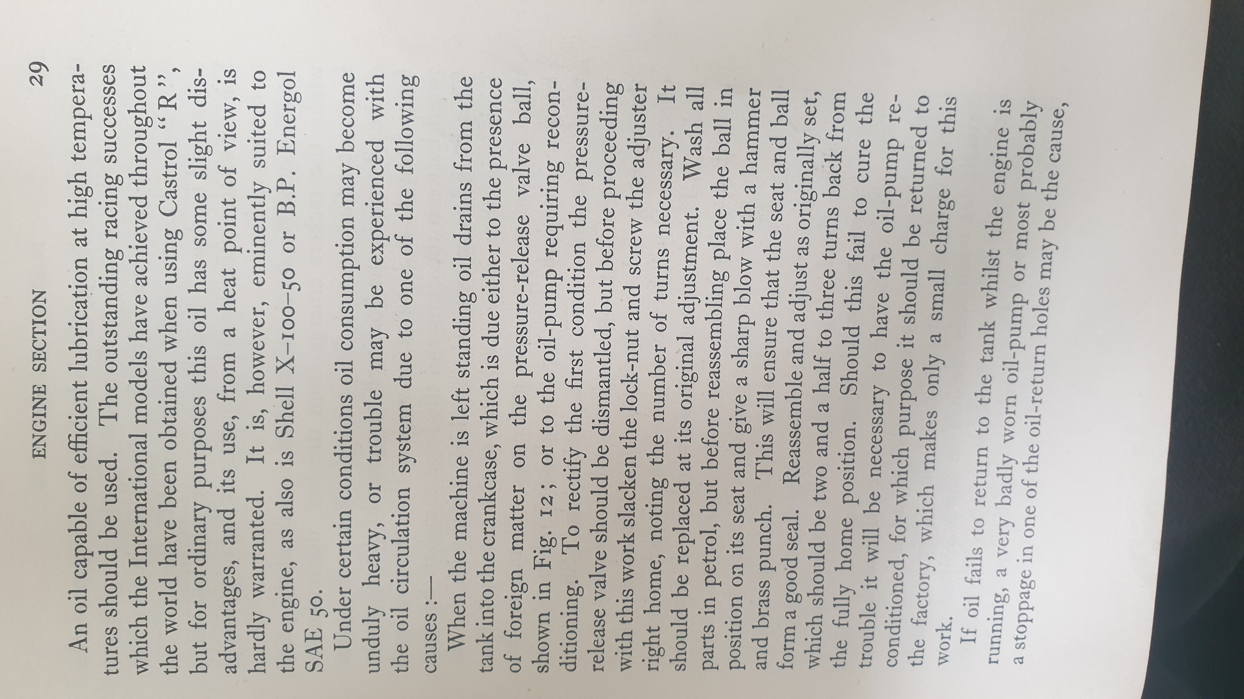
In the Edgar Franks book, he…
In the Edgar Franks book, he says that oil draining into the crankcase is either due to foreign matter on the pressure release ball valve or the oil pump requires reconditioning.
- Log in to post comments
That's why i think...
...Richard is on the right track. The profuse amount of oil outside the motor suggests to me that the pump is in good nick but unrestricted and flooding all areas.
Mike: a picture saves a thousand words.
The guy has done a nice build, I suspect something is missing.
J
- Log in to post comments
Gentlemen…
... what I’m really starting to let sink in my brain is the fact this engine was started for the first time and ran for only a few minutes and I am now taking on the troubleshooting of whatever issues there are within the seller’s build.
Richard, Jonathan, David and Michael, YES! a picture of your oil pressure gauge is worth a thousand words! What makes conceptualizing things difficult on an engine that I’ve never seen before with the ancient sophistication and complexity of the International is that whilst symptoms such as oil leaks are obvious, the cause of them is less so apparent when reading manuals and trying to visualize what is obscured by the relative absence of pictures.
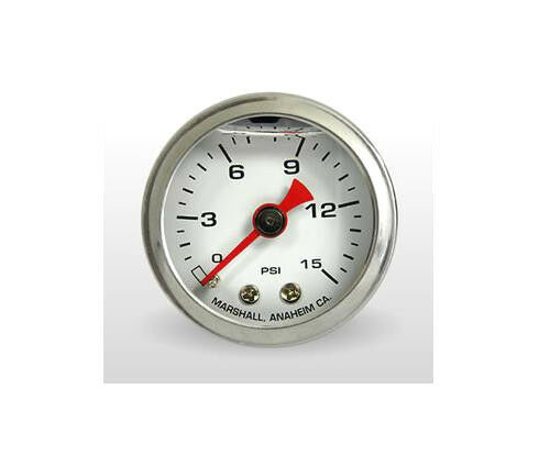
- I have a 0-15 psi oil pressure gauge coming in the mail. Clearly, I must verify what the oil pressure is...
- The “Tell Tale” pushes out oil like a wounded whale…
- I will appreciate if you can recommend a supplier for the ¼” BSP tail, I am not aware of anyone here in the colonies who supplies that large size.
- Jonathan, when you say “I suspect something is missing,” could you please clarify a bit more?
I’ve printed off an exploded view of the engine to further aid my progress… And diving into E.M. Franks, Spares, Maintenance and Instruction Manuals.
- Log in to post comments
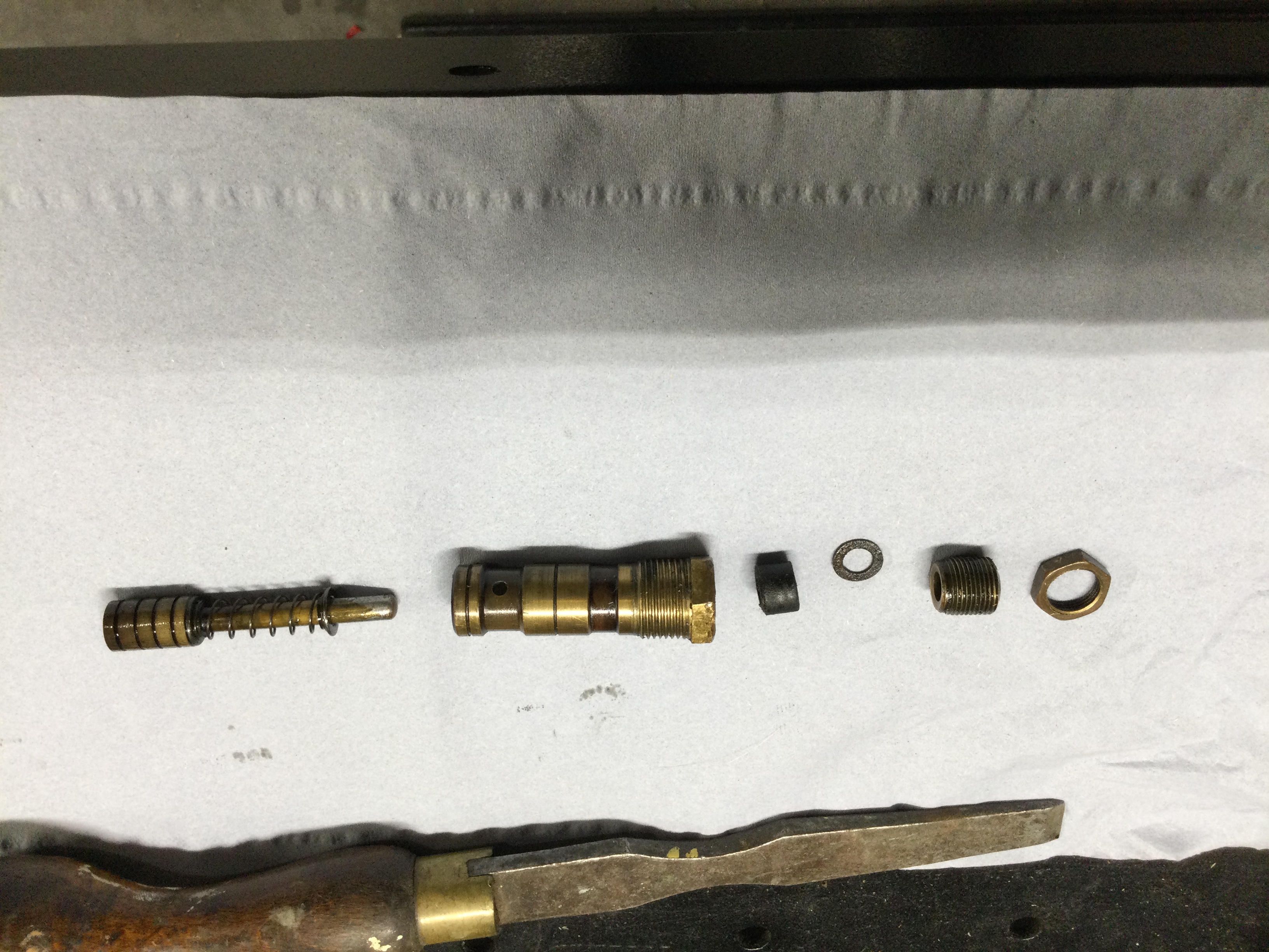
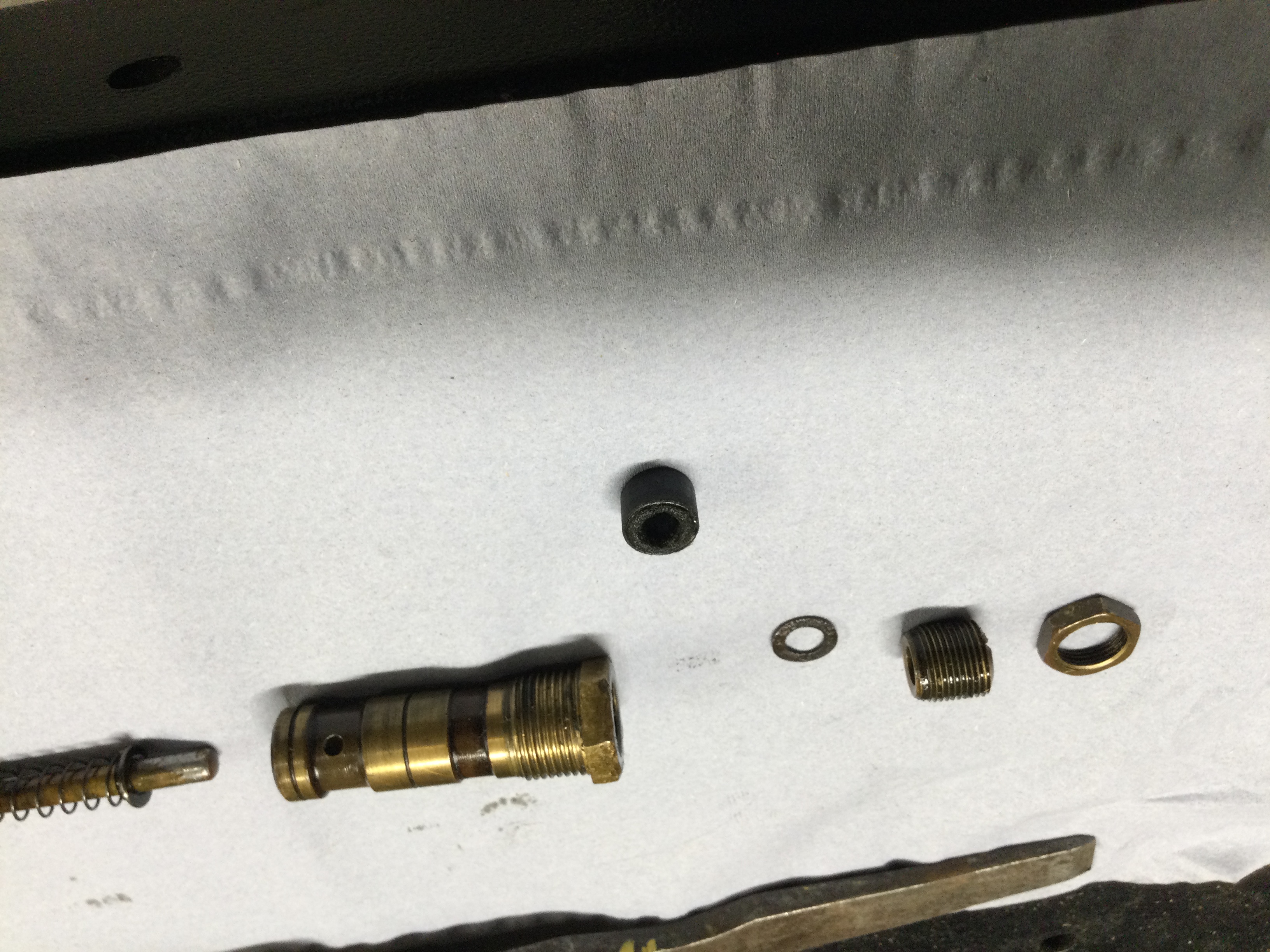
Findings upon disassembly... post 1/3
Having taken heed of everyone's welcome comments I have referred to the green factory 1946 Maintenance Manual, page 15, E.M. Franks, the Spare Parts List and the 1938 Instruction Manual.
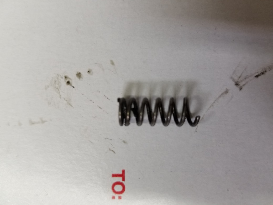
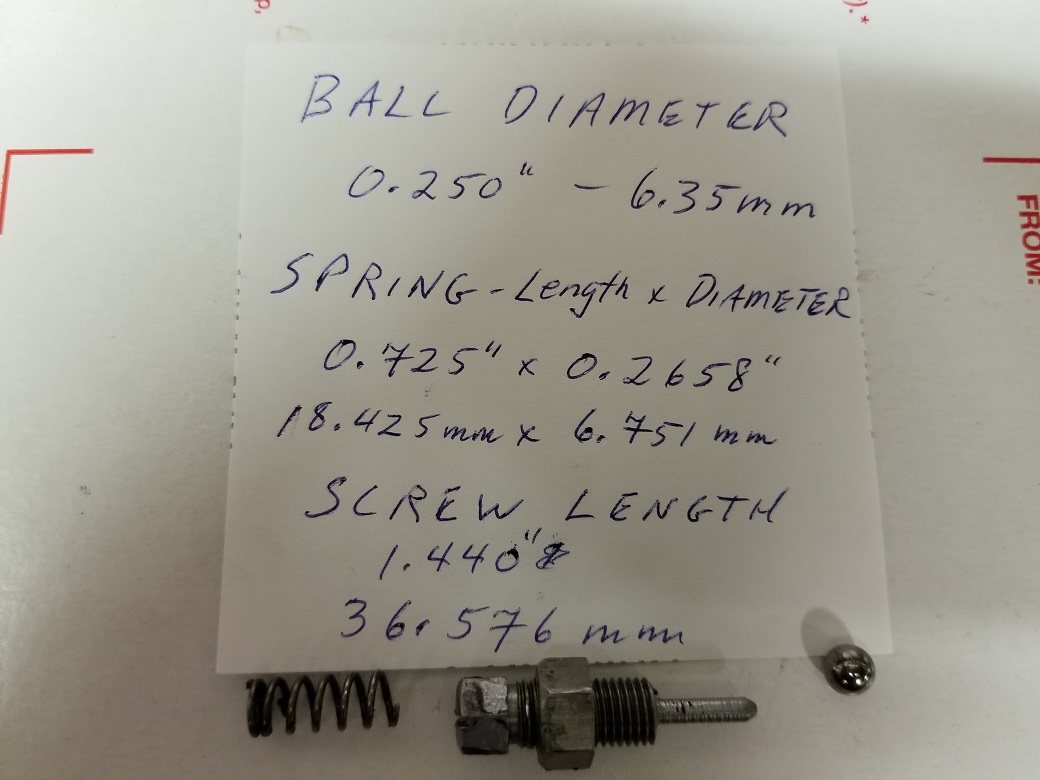
Attached you will find 2 pictures with measurements of parts. Removed the "pressure valve" with spring loaded ball. The Manual calls a 7/32" ball; the one i removed is 1/4" The spring is very stiff with 0.036" diameter coils and with one end broken off. This spring does not look like a "light" progressively wound sort of spring as shown on page 37 of E.M. Franks and in Spare Parts List. I forgot to turn the adjuster screw in to count the amount of turns out the screw was set at, but in hindsight seems moot given the spring is probably not the correct spring nor possibly a factory spring. The diameter is such that i had a bit of a heckuva time pulling it out... The Manual calls for 2-1/2 - 3 turns out. I'm going to limit my comments further and faithfully await your comments.
- Log in to post comments
Findings upon disassembly... post 2/3
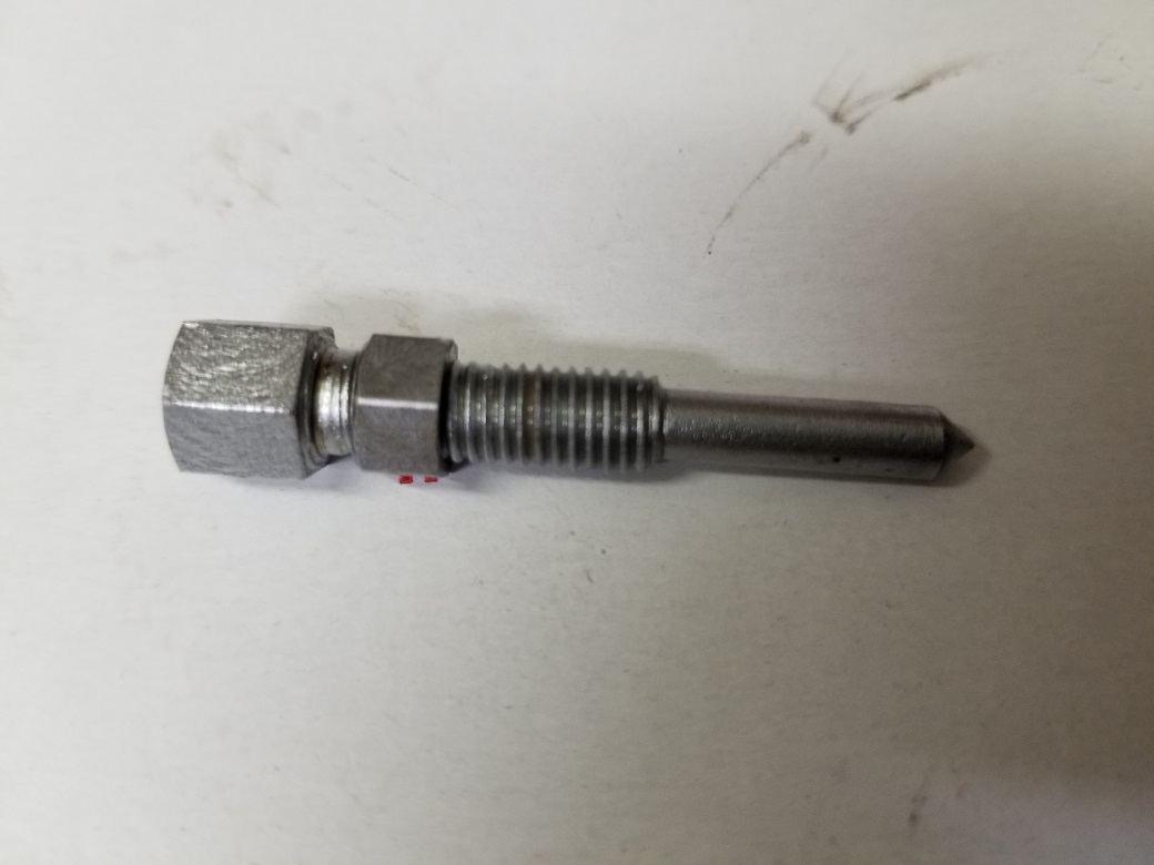
The metering screw to control the amount of oil to cambox, picture attached. Not much to be said here, this screw was turned out 2-1/6th turns; the Maintenance Manual states 1/2 turn. Will await your comments.
- Log in to post comments
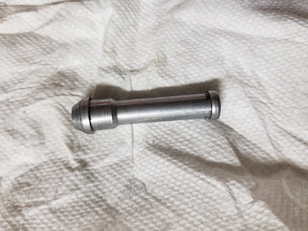
Findings upon disassembly... post 3/3
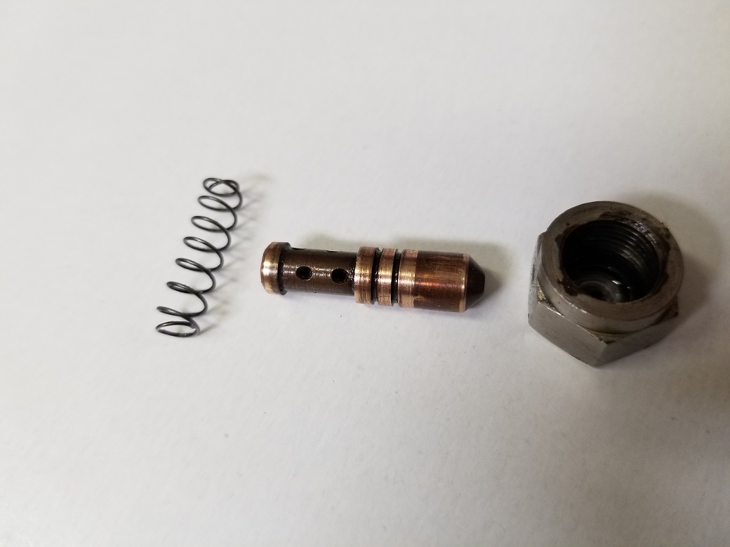
Mainshaft oil metering jet, 1 pic attached. The spring looks the one that should go with the spring loaded ball "pressure valve" noted in post 1/3...? Diameter is 0.255" Length is 0.875" and as you will note is sort of progressively wound, the coils quite thin. The sketch of the spring in the Spare Parts List depicts a "straight" spring with heavy coils, not this light spring... The "mainshaft metering jet" enters its hole with very slight resistance; once all the way home, it moves back and forth with no resistance. None of the holes appear tampered with, but then i don't know the diameter of the holes this jet left the factory with...
Given my findings shared in these 3 posts, darn good i am "going in" further.
I don't see these 2 springs listed on Paul Norman's site, have not looked elsewhere or where may i source them...?
I faithfully look forward to your replies.
- Log in to post comments
Oil Pressure Gauge Setup
The top and bottom fittings the pipe that feed the cambox are same as fuel line fittings. I went through my stuff and found these fittings (pic attached) that i intend to put a thick cloth reinforced rubber hose to each of these fittings with a T connector in the middle to accommodate a 0-15 psi oil pressure gauge (pic attached). Am i ok using this reinforced rubber hose instead of a metal pipe to obtain my oil pressure setting?
- Log in to post comments
...yes.. unless it is so…
...yes.. unless it is so sensitive to oil that it rots in the length if time you use it for...the correct pressure is not a very severe test...the original hoses were reinforced rubber
- Log in to post comments
Thanks, David...
...i figured as much, but i don't assume anything regardless what i think i know. 8 psi isn't much, and that pump is more pushing oil that creating actual pressure...
- Log in to post comments
Now we are getting somewhere....
The pressure reading will lead us on the right path. Should it read normal the following applies.
Tell tale, take it out and repack. Leather washers as I remember.
Oil pressure relief valve: If the seat is “tapped” for a 1/4 ball maybe it seals. But I would order replacements. Clue is in the name, if it is not working it’s not relieving.
The shaft metering jets look ok but check you have the smaller orifice one in the cam. I’ll see if I can track down the diameters in case they have been tampered with. I was suspecting the springs missing.
The metering screw, is for adjustment of flow to the rear of the cylinder to lube the skirt of the piston. There are two holes through the cylinder wall. The bolt is relived and the screw meters the oil into the void. If this is set wrong she will smoke out the exhaust. Text mentions a blue haze on acceleration. It’s a final adjust, don’t worry too much just yet. Set is as per book and deal with it later.
Flex hose are fine for your gauge rig and pressures we are dealing with.
What is your oil return to tank like, squirts or stream?
If you can’t source the ball and springs let me know, I’ll try UK / EU contacts if successful I’ll post them on to you.
cheers
Jon
- Log in to post comments
a single question...
...before i reply to Jonathan's comments later this evening.
have been reading literature and want to double, triple, quadruple clarify. The oil feed line from oil tank connects to the lower fitting on crankcase, is this correct? The upper fitting on crankcase is the return.
What i'm seeing in literature, ohv's are opposite, upper fitting is feed, lower fitting is return...
Thanks in advance!
- Log in to post comments
Now we're getting somewhere, page 2...
Thanks Jonathan for your reply. Addressing your comments as you presented them.
Pressure reading, yes. After i have addressed what i have found.
Tell Tale, yes. Will remove, inspect, repack with a leather washer of my own manufacture. Out of curiosity, what thickness leather?
Oil pressure relief valve... that 1/4" ball disturbs me, perhaps needlessly...? The 1/4" ball is either not sealing because the radius of the hole is 7/32" or somebody pounded against the 1/4" ball to try forcing a larger ball to fit and now the radius of a 7/32" ball is too small...? A couple other scenarios might exist that i won't belabor. Ideally, I'd much prefer to use the factory spec 7/32" ball. My only concern is i don't know the nature of the end of the hole the ball seats against, but i would think a 7/32" ball would work fine even if a 1/4" ball was pounded in...? My only fear, likely irrational, is the 7/32" ball would go through the hole and then be irretrievable... Likely not, I'll put my eyeball to things and see what i see...
Brass metering jet hole diameters; if you have them that'd be greatly appreciated.
The metering screw adjusts oil flow to back of piston... Now i know why there is so much smoking... (:
On my very first start, i did check for oil return. What i saw i seem to recall flow looked like a continuous stream, but it was only a quick glance. I need to look at the return flow again after i have remediated the issues discussed.
Jonathan, thank you for your kind offer on sourcing a ball and springs. Ideally, the solution would be to have new factory parts. The one light spring, slightly tapered at both ends, does it appear factory? Then we don't know if it's good, but it 'appears' in good condition... Is that light spring supposed to go in the cavity of the oil pressure spring loaded relief valve? That heavy broken spring, does that spring look like what should fit against the brass metering jet? At the least, i need that heavier spring, assuming that spring should not be the same as the lighter spring in the oil pressure relief valve...? the 1/4" ball looks good if i decide not to replace it with a 7/32" ball...
So, at worst case i need one new spring and a 7/32" ball. I can source the 7/32" ball, so all i would need is a new spring for the shaft metering bronze jet. My local hardware store has a spring assortment, but i don't know what spec spring i would need to select...
So, if you can provide me the one spring that would be appreciated. Or if you can source suitable replacements for both springs that would even be better. Just my thoughts... Thanks again, Jonathan; i'll look forward to your reply.
- Log in to post comments
From the top....
Top connection from tank bottom to tank see pic.
Tell tale packing not sure I’ll strip one and come back to you.
1/4” ball is a mod I read done to give better control. But that may be on a specific machine.
Crank metering quill is 0.080” and the cam one 0.044”. You may not have a cam one if there is no central feed nut on the top bevel cover.
Tapered spring looks right for the quill. It’s purpose is to hold the quill against rhe seating.
Oil pressure spring looks wrong but I forget as it’s not often exposed. The diagram shows tapered.
I’ll get some springs if they are in stock.
Better to be right at this point
- Log in to post comments
From the top, Swan reply to
Jonathan, first thank you for your patience and staying with me, very much appreciated. I'm having a bit of a struggle keeping up with terminology... I'm going to start using terminology noted in the 1946 Spare Parts List to try helping me be more clear as to what i am referring to. (I have a 1937 Spare Parts List, will use as needed, but it does not have nearly the pics the 1946 List has).
I'm not sure what you mean by "top connection from tank bottom to tank see pic." What am i supposed to be looking for in the pic?
Tell Tale packing, thanks for having one to strip and show me. I will disassemble my Tell Tale and post under the Tell Tale thread you started.
When you say "crank metering quill" what part are you referring to? (my top bevel cover is smooth, no central feed nut).
To hopefully help clarify springs: There are 2 springs.
Spring 1 is the "pressure release ball spring," which fits around the "pressure release adjusting screw" and pushes against the 7/32" ball. (This spring appears tapered on each end).
Spring 2 is "mainshaft oil connection spring" which pushes against "bevel cover and mainshaft oil connection (brass) jet." (This spring appears straight).
If i only replace the one spring that is broken, considering the purpose it serves, it would seem important to know the diameter of the coils and number of coils per inch...?
100% agreed on "Better to be right at this point."
At this point, i am going to limit my comments/questions to not further confuse things out of my ignorance and not fully conceptualizing the terminology you are using. I want to make sure i am understanding your terminology before i ask any more questions.
Again... Thank you for your help. Kind regards,
Steve
- Log in to post comments
Tell Tale, reply 1
Hi Jonathan,
I tried removing the Tell Tale but it fouls on that threaded part the cylinder metering screw threads into as you can see. With some creativity using the parts making up the metering screw assembly along with a washer i tried removing this threaded part to no avail. With the top part of Tell Tale removed, i can see packing... Not sure how to proceed from here... (Thinking cap on...)
- Log in to post comments
A tremendous help to me....
.....has been Niels Schoen's book on his uncles's Manx.
https://www.globaldimension.com/2018/05/garden-gate-manx-reverse-engineer/
It's expensive at €100 but worth every penny.
You can contact him here to arrange purchase:
newstep3d@gmail.com
All will be revealed.
- Log in to post comments


I have a couple of exotic machines that did the same when I got them. They now just leave the odd small stain after use. A smear of silicone sealant where once a smear of oil or grease would have been used has helped. Slightly underfilled with oil in all areas has helped. The 36 Rudge Ulster arrives at its destination in a cloud of oil smoke (none from the exhausts). But I know that they can be much less incontinent ,its just going to be a slow job. Copper and paper washers can only seal against surfaces that are parallel to each other, thats when the silicone gets used. Better crankcase breathing can help.