
My '73 Commando roadster has the head steady mount on the frame blanked off with molded rubber covers. Is this standard? Does this year not have a head steady?
The head steady triangulat…
- Log in to post comments
Previously wrote: The head…
Previously wrote:
The head steady triangulation is absolutely vital to the Commando. You wouldn't get me on one without a steady !
The standard steady relies on bonded rubber silentbloc fittings for its resilient mounting. Could it simply be that the outer plate and stud has sheared off leaving a stud with bonded rubber in place ?
At the very least, fit a box-section 850 style head steady, although a big improvement can be made by fitting a rose-joint system such as the 'Dave Taylor' steady sold by RGM.
- Log in to post comments
I'm with you there Richar…
I'm with you there Richard. But the haynes manual shows a mount on the frame to bolt the head steady thro. Mine just has these very perished bonded bungs where the hole should be. I have seen the mount on a '68 commando and the head steady from that would just not fit to my frame without drilling out the bonded bungs to create a hole thro to mount the steady. Very strange!!
- Log in to post comments
Does seem that the end pla…
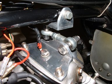
Does seem that the end plates and studs have been removed or sheared. What is on the head itself? Any pics? Below is my home made steady based on a US design that bolts to the original rubber mount points. No extra vibes and restricts side to side rotational movement superbly.
Attachments
New-Head-Steady-014sm.jpg
- Log in to post comments
When I got the bike it had…
When I got the bike it had no head steady fitted at all. It has the standard three mounting holes on the head. I have had the frame stripped and is in the powder coaters at the moment, but have cut off the wierd mount on the frame and put it back to a standard setup ready to either manufacture a steady of our own design or copy an existing design. Yours looks interesting Keith, thanks for the pic.
- Log in to post comments
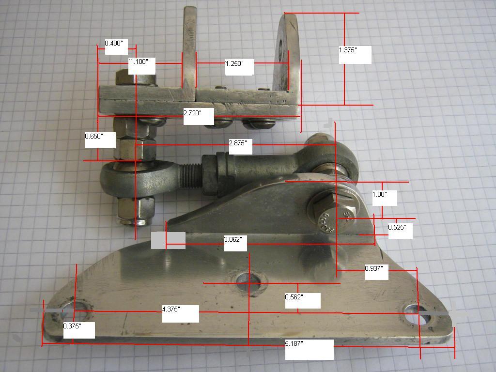
Here are basic dimensions…
Here are basic dimensions for mine. If I did another I'd raise the mount on the head and eliminate that spacer nut on the frame bracket. I used 3/8" rod ends, one male and one female. Material is 2" x 1.5" x 3/16"aluminum angle bolted together.
Attachments
Headsteadydimssmall.JPG
- Log in to post comments
Previously wrote: Here are…
Previously wrote:
Here are basic dimensions for mine. If I did another I'd raise the mount on the head and eliminate that spacer nut on the frame bracket. I used 3/8" rod ends, one male and one female. Material is 2" x 1.5" x 3/16"aluminum angle bolted together.
Nice work Keith, and thanks for posting the pictures and dims. I have a few questions:
1) Are there any clearance problems between the mounting bolt of the frame mount and the petrol tank tunnel?
2) You refer to 'raising the mount on the head' if you were making another, Do you mean putting a spacer plate under it, or increasing its height so that the rose joint is higher up (negating the need for the locknut?) In either case, would this cause any tank clearance problems? (the horizontal tie rod being wider than the frame mount)
3) Have you tried this head steady with the Mk3 spring arrangement?
Sorry for the 3rd degree, but I intend to have a go at making one, and I want to be sure I'll get it right!
Allan.
- Log in to post comments
Allan, No clearance probl…
Allan,
No clearance problems with my steel Roadster tank. There is about 1/2" between outer end of rod end and tank. If this was raised as per(2) it would still clear. You can make the link shorter of course depending on the min centres you achieve with 3/8" or 10mm rod ends.
Yes, I meant eliminate the full nut as a spacer and raise the link so there is less stress on the bolt, although there would then be more stress on the aluminum (though unlikely to be an issue since the loads are across the frame). What is important is to shim the link so it is parallel with the engine and ISO's when the bike is on its wheels. A half nut as a spacer would be a compromise.
No I haven't tried the Mk3 arrangement though I know the RGM 'Taylor' steady has this as an option. Theirs is basically the same design but mine came from Mike Taglieri on the original NOC 'notes' site. His was in steel which is what I tested and then decided aluminum would be nicer.
I was truly surprised that vibration was not increased but had I thought about it I'd have realised that since the whole assy is allowed to move in up/down and front/back planes where the engine vibrates.
Try it, I think you will be pleased with the results. You may have to trim a little material here and there as I recall the lower nut on the vertical bolt did contact the aluminum brkt with the bike in use on the road. I took a pic which is here along with other views of the mount in Photobucket at
- Log in to post comments
Hi Keith, Thanks a lot for…
Hi Keith,
Thanks a lot for the clarificationand your photobucket link. I've already ordered some rose joints from McGill on ebay.
Allan.
- Log in to post comments


The head steady triangulation is absolutely vital to the Commando. You wouldn't get me on one without a steady !
The standard steady relies on bonded rubber silentbloc fittings for its resilient mounting. Could it simply be that the outer plate and stud has sheared off leaving a stud with bonded rubber in place ?
At the very least, fit a box-section 850 style head steady, although a big improvement can be made by fitting a rose-joint system such as the 'Dave Taylor' steady sold by RGM.