
Hi,
I managed to separate the crankshaft journals eventually and with difficulty. None of my spanners seemed to really fit and I came close to rounding some of the nuts on the end of the studs since only flat spanners seemed to fit (not enough room for ring spanners). Also, I only just managed tp get a socket onto the outer studs and then it wasn't truly perpendicular.
So my question is does anyone know of a solution to this (suitable spanners or something) and if so where I might purchase said item(s). I'm a bit nervous about this 'cause I've got to do things up really tight!
Thanks all!
keith
Crows Feet Spanners
- Log in to post comments
If the calculation required…
If the calculation required is too demanding, it can be avoided by ensuring that your torque wrench is positioned at 90º to the axis of the crows foot spanner.
- Log in to post comments
I have just finished…
I have just finished reassembling mine . 1/4 “ drive sockets worked fine and extension to get past crank web then 1/4 to 1/2 adapter to torque wrench. The bottom two with tab lock plate I did by feel .
Mick Hemmings is ok with this on the club video.
I purchased all new bolts / studs / nuts from AN . The fillet at the crank flange encroaches the bolt circle for the top two bolts . This area is spotfaced to create flats for the boltheads/nuts . I found I had to turn down the bases of the new long top nuts because the diameter of the spotface is less than the distance across the points of the nuts and consequently the nuts foul on the spotface . The original nuts were turned down this way . Apparently at some point Norton increased the diameter of the spotface to eliminate the need of turning down the bases of the nuts.
I have been in communication with Simon @ AN regarding this - It would be interesting to see at what point the change was made.
- Log in to post comments
crankshaft bolts
Hi,
Thanks for the feedback. I watched the club video again last night - very informative although my wife thinks I'm a bit obsessive (but then I don't want things flying apart at some point in the future)!
I don't have any 1/4" drive sockets, but, I do have adapters and with an extension and the right sized socket I guess I should be o.k. Anyway, these things are not expensive!
I hope I don't have to resort to such extremes as turning down nut (mine's an 850) since I don't have a lathe.
BR,
Keith
- Log in to post comments
Crank Nut Access
Keith,
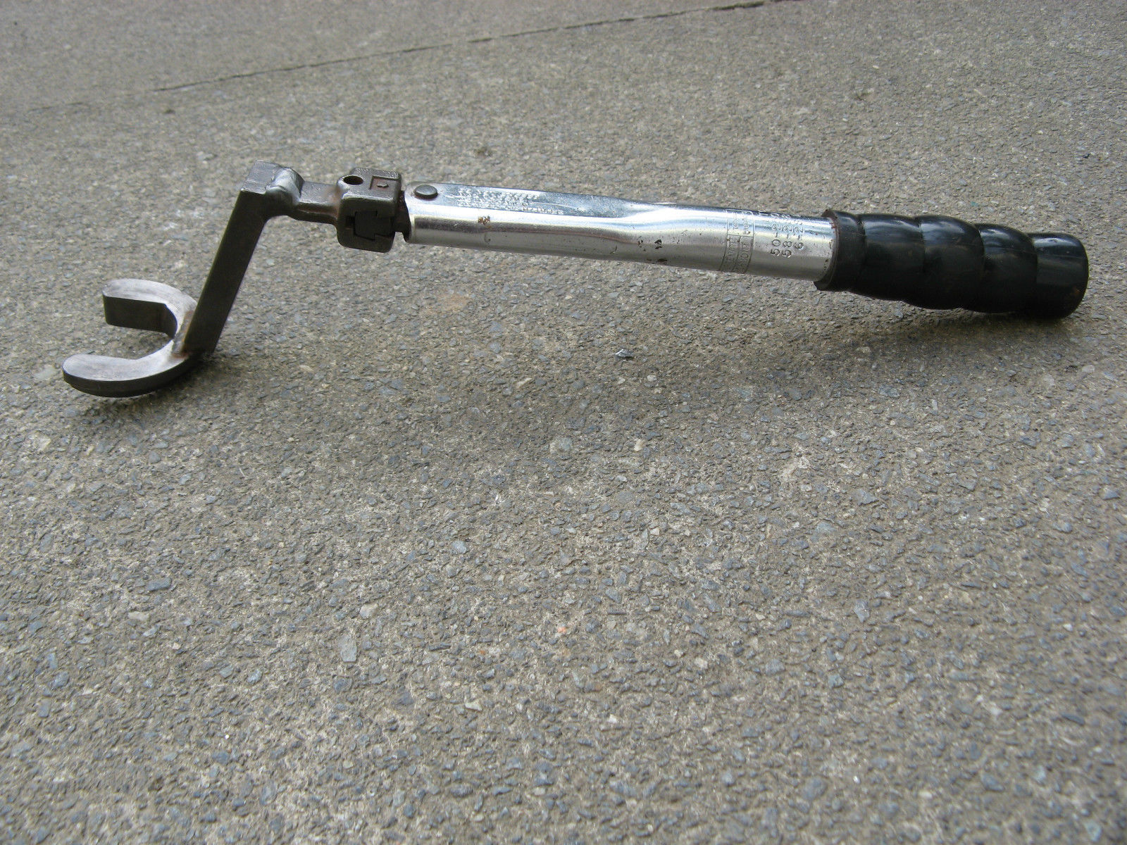
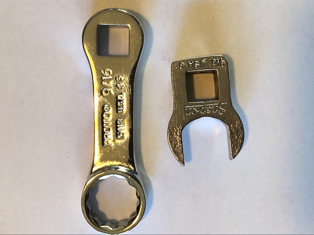
See the attached photo of two extensions I bought to assist with torque-tightening. The ring extension was from Amazon and the open-ended cows foot off eBay - the latter is supposed to be Snap-on, but i have never seen such a crudely finished Snap-on tool, so am suspicious of its true origin.
Richard,
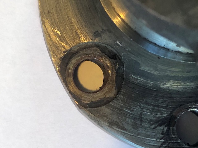
The attached photos show one of the flange top nut locations on the crank from my currently stripped 1976 Mk3 Roadster engine (333764). The nuts have a plain hex without machining, as can be seen by the pre-clean contact surface.
Regards,
Andy
- Log in to post comments
Andrew - Simon from AN…
Andrew -
Simon from AN says factory specs for spotface diameter call out .656”
Can you measure yours and also determine date of manufacture ?
Thanks - Richard
Keith -
850 cranks may be ok with full nuts - in the event that they are not you can file off the corners around the base of the two top nuts if needed - no need for a lathe. Also the club video is very good indeed but it does not touch upon the subject of end float in the crankshaft. While my original bearings were not shimmed, I found I had to shim the new bearings to keep the float within .005” - .015” tolerance. The replacement bearings measured .003” less in depth than the originals. Mine is a 750 - end float specs may be different for 850.
- Log in to post comments
Hi, Yes it is interesting…
Hi,
Yes it is interesting to note that not much mentions seems to be made of end float anywhere.
I guess the ideal is to shim both sides of the crank equally, should end float be excessive.
I noted that in the video there was mention of grinding two chamfers on the rear face of the inner races, prior to fitting, to make it easier to engage the extractor if removal is ever required; I guess this could be useful if it is necessary to shim the crank.
Keith
- Log in to post comments
The chamfers are a good idea…
The chamfers are a good idea in the event that the inner races need to be removed in the future but any shimming is done between the outer races and the crankcases . I turned two dummy bearings which matched the depth of the new bearings but sliding fit diameters so to avoid heating the cases again and again - the play in the bearing cage/rollers/ outer race must be considered when doing this as I found to my dismay.
- Log in to post comments
Spotface width
Richard,
The spotface width for all four top nut locations was 0,712", measured with a digital caliper - not that easy to measure, as apart from the the quadrant closest to the big-end journal, there is circumferentially little depth to cleanly pick up on. However, the measurement obtained was pretty repeatable at the four locations, give or take thou or two.
Re shimming the main bearing inner races, a certain Midlands Norton specialist once advised me that setting the crank endfloat was unimportant, as the oil pump gear drive will keep the crank drawn towards the timing side.......hmmmmm......
Andy
- Log in to post comments
It seems some are…
It seems some are indifferent to crankshaft end float - I suppose an argument could be made that at worst excessive float could cause premature wear on the timing components. It makes sense that the worm gear drive for the oil pump will draw the crank towards the timing side - at least during acceleration. Although I doubt the oil pump has enough kinetic energy /momentum, the opposite effect may be had to some degree upon deceleration. This being my first Commando engine rebuild I thought it wise as well as increasing my skill sets to try to obtain the recommended amount - my sources recommended .005” - .015” .
Trying to avoid excessive heating / cooling / reheating of cases and bearings I turned two dummy bearings that matched the width (depth ?) of the new bearings but diameters of a sliding fit . When dry assembled the float was right at the minimum of .005” - after putting in the actual bearings I had float of .016” . Where did I go wrong ?
Turns out I didn’t take in to account the collective amount of end play between the rollers/cages/ outer races so I wound up having to reheat all / shim .003” each side/ heat again and reinstall the bearings which gave me end float of .010” - smack in the middle so I am happy with that.
Hopefully always learning - RT
- Log in to post comments
Addendum
In thinking about this end float business I believe it’s importance lies in giving the crankshaft room to grow. The forces acting upon it during the upper 180 degrees of rotation- particularly at TDC - must push the journals towards the mainshafts and thus expand its length . If you bend a piece of wire into a crank shape and place the mainshafts on a flat surface with the crank pin / journal standing squarely above and push down on it you can see this in action. So even though the crankshaft may be pulled over to the timing side, it still has room to grow at the other end . Without this room the expansion would strain the bearings and cases in thrust loads . Makes sense ?
- Log in to post comments
box spanners
hello for some hard places to get into a good set of whitworth box spanners do help and if you fit a socket on the other end you can use your windy gun and then the toque wrench for the settings so make life easy yours anna j
- Log in to post comments
Crank end float.
I set my Ducati up with zero float. Not easy with soft case gaskets!.
- Log in to post comments
Crankshaft Growth
In my Notes regarding crankshaft assembly written by the late John Hudson. He mentions that the end float for Commando engines was increased to 20 thou to allow for the flexing of the crankshaft at high revs. He also mentions occasionally finding up to 40 thou float on some relatively new engines he did warranty repair work on.
With regard to using crows foot spanners or similar on a crankshaft, there are several good postings on this Forum. Use the Search Box above to find them. One gives the number crunching required to set a torque wrench with either a normal spanner or CF extending its length.The general consensus being that the wrench and any extension need to be in a straight line (180*) and acting directly on the nut being torqued. Anything seriously deviating from this will mess up the torquing value. So a CF angled at 90* in a torque wrench head does not work.
- Log in to post comments
Hi, I contacted Andover…
Hi,
I contacted Andover Norton and was told that the nut size for the crank studs fits a 1/4" whitworth spanner;
I tried a number of different sockets and spamnners and found that the whitworth is a loosish fit on my replacement nuts. A 13mm metric is better and a 1/2" AF better still (but still a tiny bit loose).
I have ordered a 1/2" AF with 1/4" drive and an extension bar, in the hope that it will be thin enough to pass the cheek on the journal whilst maintaining a square fit to the nut (my long reach 3/8" drive socket is too fat to go over squarely). According to the club video, the outers are torqued and the rest just done up really tight,..................we shall see!
Concerning the shimming, I imagine that as the crank cases heat up, the end float increases. I guess all is ok as long as there is sufficient clearance, with a hot engine, between the inside of the bosses of the pistons and the small ends of the conrods to prevent the small ends interfering with the pistons, since there seems to be no general consensus as to how critical this is?
Keith
- Log in to post comments
If you're buying tools for a specific job …
If you're buying tools for a specific job there's no reason not to modify them — so if your new one-off socket (etc.) is still a fraction too chubby, just grind to fit.
- Log in to post comments
Assembling a twin crankshaft
HI, I decided to clean out an Atlas crankshaft. No problems really, just find all my old whitworth spanners and sockets, files and possibly a spotface tool. Once apart, clean all the old oil sludge, pipe cleaners down the holes, blow out with an airline, and assemble. I always modify tools to fit, so as I have boxes of tools bought from boot sales, they are disposable. Shimming the crank for end float. My tips. Bolt the crankcases together. Measure the distance between the bearing abutment faces, record it. Measure the crankshaft width where the bearings locate, record. Measure both bearing widths, record. Add the crankshaft and bearing dimensions together, and take the result away from the crankcase gap. This will give the space to shim, or not if a minus result. If one uses two solid bearings, then 0.010 theoretical end float is fine for expansion. The Superblend story is an urban myth. (A minefield of non engineering claptrap) Use NUP306E M1 both sides, as the crank is located on the timing side. Do not buy un-branded Chinese steel or plastic cage bearings. I am putting an 850 11a crank in some Mk3 cases, which need 0.028" shim both sides Behind each bearing. If you grind flats to get the bearings out later, do not forget to wash them out in petrol, and re-oil before assembling. I have proper bearing extractors that will get them out later. I hope not to in my lifetime. Original nuts had a machined diameter under the flats to stop the flats bottoming out in the spot faces. The crankcases being aluminium expand more than steel, so a flexing crank has plenty of room to bounce around. Why not fit a late Triumph twin crank instead, I will have a measure and see. I had a look at Nourishes shed when he put up all his old Tat for sale, made me feel all funny, just like the old BSA works, no change from 1914 to 1972, all those lovely old clapped out machines and a bit of fence wire holding it all together. Please, no Trolls feeling sorry for the old machines, I spent a lifetime getting them to work to tenths. I nearly bought Hesketh off the receivers too, better stuff, but too many bean counters running away with the money. Lovely engine.
Has anybody a set of N15cs footrest brackets looking for a retirement home? My next job.
- Log in to post comments


![IMG_0885[1].jpg](https://www.nortonownersclub.org/sites/default/files/2019-09/IMG_0885%5B1%5D.jpg)
I am fairly certain that this item has been covered on the Forum before and good suggestions can be found by using the search box. In my case I have assembled a collection of ring spanners with differently angled heads. In the USA you can purchase a tool called a Crows Foot spanner. These are purpose built for difficult tasks such as recessed nuts and bolts. The problem here being that there are not too many of these items about with CEI/BSC nut sizes.
The other problem that you will encounter is the maths required to torque up all these fittings when assembling the crankshaft again. The attachment shows one solution to this.