
I have a "hybrid" bike which I am very slowly doing up. It has a rather idiosyncratic 12V wiring set up so I have decided to rewire it from scratch.
This is the first time I have done anything similar to a bike (although I have built a Westfield) and I'm a little apprehensive of just winging it.
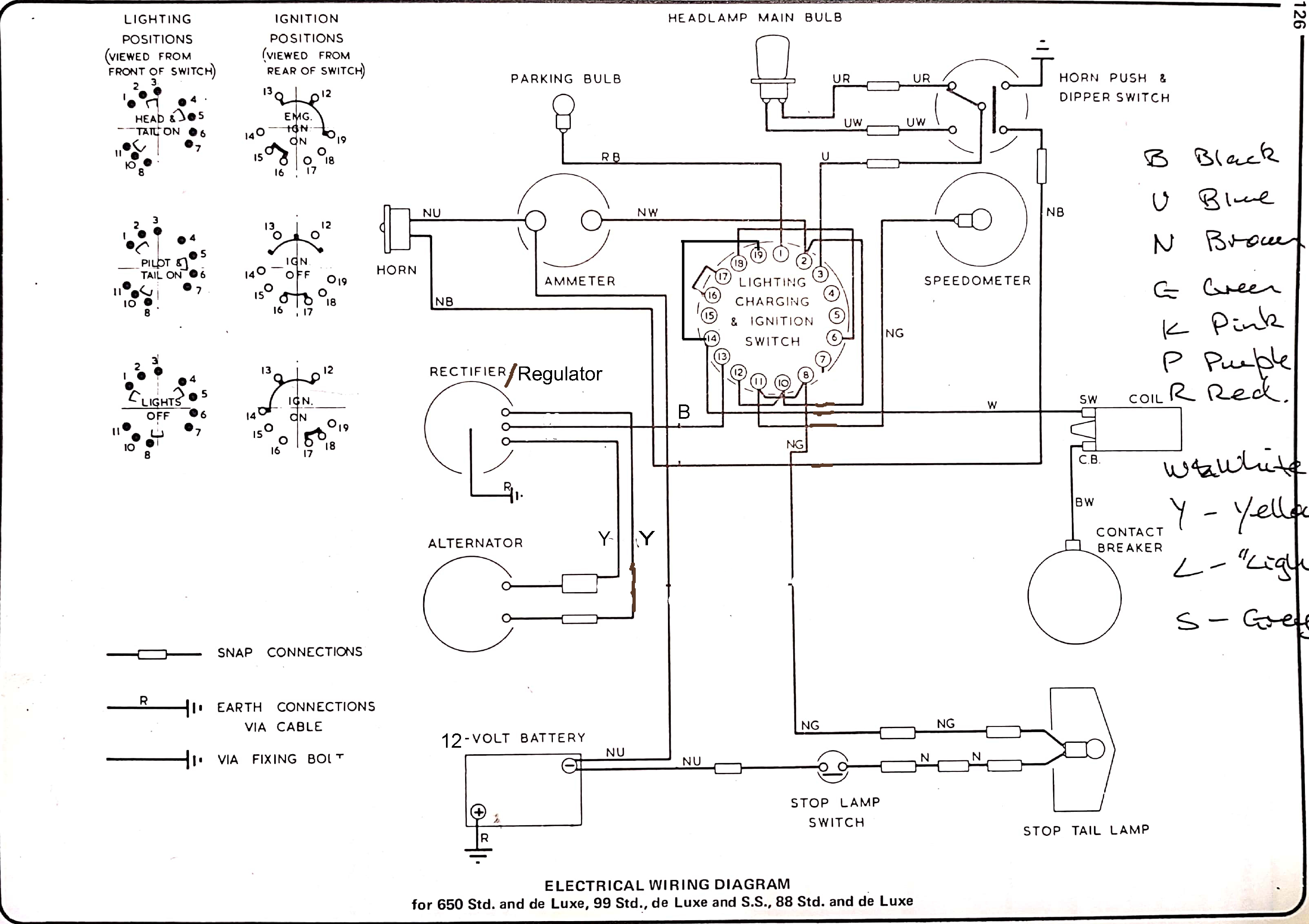
I've modified the Norton circuit diagram (attached below) to use a modern rectifier/regulator with the existing two wire alternator. I don't think I need the bike to run in emergency mode. I intend to keep the bike +ve earth, mostly out of sentiment.
Would any passing sparks be able to give the diagram a look and let me know if it makes sense and if it is likely to work?
Finally, a quick question. There is what appears to be a small capacitor connected to the condensor and earthed to the bike. Is this essential, desirable or not needed?
Many thanks,
Derek
Diagram here, I hope.
- Log in to post comments
three stage electrics
Hello for simple electrics you need to dump the prs8 lighting switch and its wiring diagram and the RM15 alternator to , and use the Sa88 switch for lighting and a key ignition switch and replace the alternator with a pit bike fly wheel lighting and cdi ignition cost around 25 quid new, all these parts are on ebay pit bike lighting is 12v 65 watt for charging the battery the pit bike fly wheel will need some work in machining the center to fit the Norton crank end then mount to the original alternator mounting bracket your ignition is battery free self generating like a magneto, but without the points just wire one side tought the key switch on/off and your lighting though the sa88 you indicators on a seperate loom wired thought a lucas head/dip switch for the handlebars on you right side next to the throttle and one the same for dip/head switch next to the clutch lever and fit royal enfield bullet style indicators fitted to a short alloy flat bar to avoid drilling in to the Norton tin wear try this out a see how it goes good luck yours anna j
- Log in to post comments
My 99 has a similar set up. …
My 99 has a similar set up. I have added a 2MC capacitor and spring as fitted to the later bikes which enables a flat battery start and running with the battery disconnected if it fails in use(get you home)!.Its also very simple and can be disconnected if it also fails in use.The small capacitor is maybe a replacement for the one that lives inside the distributor, I have also got one fitted on the coil(not the best place normaly) but not connected ready to substitute for the internal dissy one(get you home)!
as they can fail and stop the ignition.
- Log in to post comments
I think you might add a fuse…
I think you might add a fuse on battery connection. Just to minimize the risk of the famous Lucas smoke. Also think at least twice on all earth connections. Not neccesary but if you have different coloured wires, it's much easier to sort it out. Did a 99 wiring in my youth, all black.
- Log in to post comments
Thanks Robert and Mikael. …
Thanks Robert and Mikael.
Mikael, to misquote Yes Prime Minister, "All black wiring? That's very brave, Sir!"
Cheers,
Derek
- Log in to post comments
Looks pretty good to me.
But I would fit a fuse in the battery earth lead as this avoids the possibility that a carelessly wielded screwdriver can melt everything. I would also run dedicated earth leads to the headlight and rear light direct from the frame earth terminal as otherwise you're depending on grease, paint etc to return the connection. I also fit an earth lead from the engine to that earth point to make sure the contact breaker has good continuity.
- Log in to post comments
In the best tradition of …
In the best tradition of Bodges I have installed a long "chock block" (horror!) which I run all the earths to ,this is cable tied to the frame and means I have only one lead to the battery. All nicely concealed behind the DL panels, See? they are good for something. And I feel better now I have confessed.
- Log in to post comments
Ian and Robert,Thanks for…
Ian and Robert,
Thanks for the confirmation that I'll need to run a number of extra earth leads. I'd worked out I might have to as the nice powder coating I've had done would otherwise need to be sanded off in places to give electrical continuity.
Cheers,
Derek
- Log in to post comments
eatrthing
Lots of earths is a good thing. The most important is a wire from the headlamp to frame earth. Brit bike manufacturers expected the lighting earth to pass through the steering head bearing. Not too bad if it's dry, but crazy people who actually grease the head races make earthing a bit dodgy. Soo... add a wire. Your lights will be brighter. Every little helps when you have a 24W or 36W tungsten bulb.
Paul
- Log in to post comments
You can continue with the…
You can continue with the PSR8 just with a simpler layout. Mine has run like that for 25years..However with the addition of modern voltage control, High output alternator,Indicators,heated grips,power sockets for sat nav and heated jacket, Electronic ignition ,extra running lights,battery less running et al, I think its time for a rewire. Need to retire that black sticky tape!.
- Log in to post comments
Nobody
Nobody has yet mentioned anything about wire gauge yet. I usually use 2.5 sq mm for leads carrying up to 10 A, and 1.5 or 1 sq mm for small loads.
Robert, if the black sticky tape has survived 25 years, it must be much better than the period rubber ties. If not overly concerned about originallity, modern things like Ty raps and shrink tube are handy. Back in the sixties, I used electrical tape on the then unchromed stanchions between the yokes Kept them rust free.
- Log in to post comments
Overkill?
I use thinwall cable from Autosparks (formerly I used VWP but they're too expensive these days).
They both advertise their 1 sq mm cable as being able to handle 16.5 amps and I've found a very brilliant light on my 6 volt ES2 using that cable. Let's face it, the ES2's dynamo only puts out 45 watts which is 7 amps or so.
I know everyone says use as thick cable as you can get but I've not had a problem with the lighter stuff.
- Log in to post comments
Cable
Careful with your choice of cable. The 'current' limit on these bikes cables is dependant on the temperature the cable runs at, so the older standard 1mm sq carries exactly the same current as the Thin Wall 1mm sq BUT the thin wall (with thinner higher temp PVC) is said to carry the extra current as it is allowed to get warmer ie does not melt so easy. 1mm sq running at 16 Amp as opposed to the standard 1mm sq at 9 Amp will actually have more volts drop. So beware Thin Wall might appear carry more current but it just runs a little warmer (and smaller). If you really want decent 6V then I suggest you use Thin Wall 2.5mm sq which will be the same physical size as the original cable but being larger cable cores will have less voltage drop for the same usage.
Dommie diagram-fine except for lack of a fuse. also the Reg/Rect output instead of being to 13 (PRS8) take it direct to the ammeter., but you will still need a feed back to 2 or 13.
Glad to see AJDs input to this problem is ignored.
- Log in to post comments
There are several prints of…
There are several prints of that wiring diagram and not all identical. Fuzzy memory tells me that if it won't work there is an error and I think it was a link wire on the PSR8. Perhaps Alan knows?.
- Log in to post comments
Thinwall cable
I take Al's point and always respect what he says. However, for my application (ES2 with 45 watt dynamo and 24 watt main beam), I don't think the 1mm squared will be overloaded....
My lights are very bright and haven't noticed any warming of the cable. To be honest however, it's probably not worth skimping. The main advantage of the thinwall cable is its smaller diameter so can be fitted into tight spots.
I'm interested in what you say about it taking higher temperatures as the one thing I don't like about it is the fact that the insulation seems to melt more readily when soldering unless I'm very quick.
- Log in to post comments
Thanks for your comments…
Thanks for your comments everyone.
I'll rewire the bike once most of the main electrical components are back in place. It might be a few months yet!
Cheers,
Derek
- Log in to post comments
Thinwall again
Ian-I have not mentioned any potential overloading of the cable. Standard cable-as the bike was wired from the factory can stand 9A before there is any heating enough to cause concern. Thinwall can take 16 Amp before any cause for concern! But your motorcycle will hardly ever take 4 Amp for the headlamp, even both beams on will only just push the cable to its limit in ambient air-rushing down the road it will be safer. BUT using standard cable or thin wall at 1mm will still have exactly the same voltage drop-which is in effect a loss of voltage.
With regard to fitting 'universal components' if you don't know what you are doing/fitting or you are fitting bits 'your mate says' (or AJD) then of course if it dosen't work it is down to you. But if you fit parts recommended by some one who knows what he is talking about and is prepared to back the product then you might be advised to go down that route.
- Log in to post comments


..