
I was just replacing the screw in the crankcase with a stainless one, when I wondered about making a timing tool.
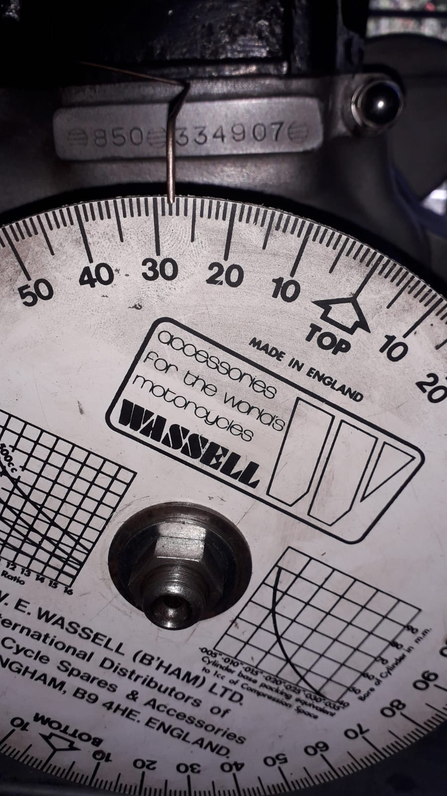
I find a 3/16" drill sits snugly in the slot in the crank. Having a lathe, I was thinking of drilling the old screw 3/16" to make my own tool. As the scale at the window in the clutch case is adjustable, would my tool give me a more accurate 28deg. position, then I could line up the adjustable scale for using a strobe?
Just check the scale in the…
- Log in to post comments
Small Triumph twins..
.. use a similar arrangement for timing. But as Peter said, you need to check with a timing disc and piston stop.
- Log in to post comments
It strikes me as strange…
It strikes me as strange that Norton would go to so much trouble to machine a groove in the crank for timing if it wasn't accurate?
- Log in to post comments
It is not unknown for the…
It is not unknown for the ignition timing plate to be out of kilter on some engines.
If you have the means the suggestions above will stand you in the right ball park. Its never wrong to verify previous established practices as often discrepancies are found.
Norton are not immune in this area for inaccuracy.
- Log in to post comments
The factory drawing of the…
(Edited)
I have done just what you suggested and made a 'bung' with a hole for a 3/16 drill.
This then locks the crankshaft at 28 degrees, then you can check the scale in the inspection hole is spot on, as it mounts on slots, it could be out by a few degrees either way..
- Log in to post comments
Timing slot
There's a tool available from AN but I centre the Mk3 crank slot by eye. The 28° was checked years ago after balancing the crank, it was spot on. Also put a TDC centre punch mark on the crank as a reference.
I use the slot to set the Trispark with its inbuilt LED, a very simple, accurate process. Never used a strobe to check, even prepping for a dyno run.
I marked 28°on the primary as a backup because the original scale was miles out.
It's more likely this will be inaccurate rather than the factory machined crank timing slot as Peter Finlay suggests.
A lot of room for error with a timing mark on a keyed 74mmø removable rotor made by different manufacturers..
- Log in to post comments
Timing Slot in Mk3 Crank
I'm confused by this discussion and wary of questioning others who are much more knowledgeable than I. I've previously asked Ashley (Andover Norton) what position the crank is in when their crank locking tool is inserted.
I was told 30 degrees.
Why was this not covered in the original workshop manual?
- Log in to post comments
I would very rarely disagree…
I would very rarely disagree with Ashley, but there is no doubt it is 28 degrees. Although the crankshaft drawing we have both seen, shows the slot at 30 degrees, because of an earlier question doubting the angle, we have done measurements on at least four 850 MkIII's
top dead centre was very accurately set and then the engine rotated until the peg dropped in the slot, this was exactly 28 degrees.
I have just checked back through the email conversation in 2022 with Ashley, and we came to the conclusion that the drawings are so poor and there were so many changes, that they cannot be relied upon. But I can state that on all 850 MkIII's tested, it is 28 degrees.
- Log in to post comments
Either way, if you have a…
Either way, if you have a MK3 use the slot, it works a treat. The new cranks are 30 degrees. Why would Norton use a slot? the answer is easy Electronic ignition - the number for it is in the MK3 parts book, it would have made setting up the ignition easier. Some of you out there also have cranks on pre-MK3 bikes that were also configured for electronic ignition, it was not a new idea for the MK3, there is hole on the flywheel where a trigger was going to be fitted.
- Log in to post comments
MKIII Timing Tool 06.6473 - where is the bolthole for this tool?
Recently bought a MKIII and considering the conversation about potential timing scale being out of alignment I have bought the crankshaft timing tool to check this - I haven't crawled about under the engine yet but can someone tell me where bolt position for this tool is? Thanks.
- Log in to post comments
MKIII Timing Tool 06.6473 - where is the bolthole for this tool?
Got it thanks. This bike still has points ignition and I strobed both cylinders and checked the mechanical advance and its spot on 28 degrees at 3000 rpm. Starts instantly and pulls smoothly but am getting some pinking under load (4th gear uphill) above 1/3 throttle so will check if timing scale is accurate - other than that it is running real well and I am minded to keep the Points considering relatively low annual mileage.
- Log in to post comments
Hi Ashley, When you say …
When you say 'new' you mean the ones you make /sell:-
850 CRANKSHAFT (ONE PIECE) BALANCED
part-no: 06.4254
As you made it, then it can be guaranteed to be at 30 degrees.
All original ones will be 28 degrees.
Regards
Tony
- Log in to post comments
Tony, that is correct…
Tony, that is correct exactly as per the drawing.
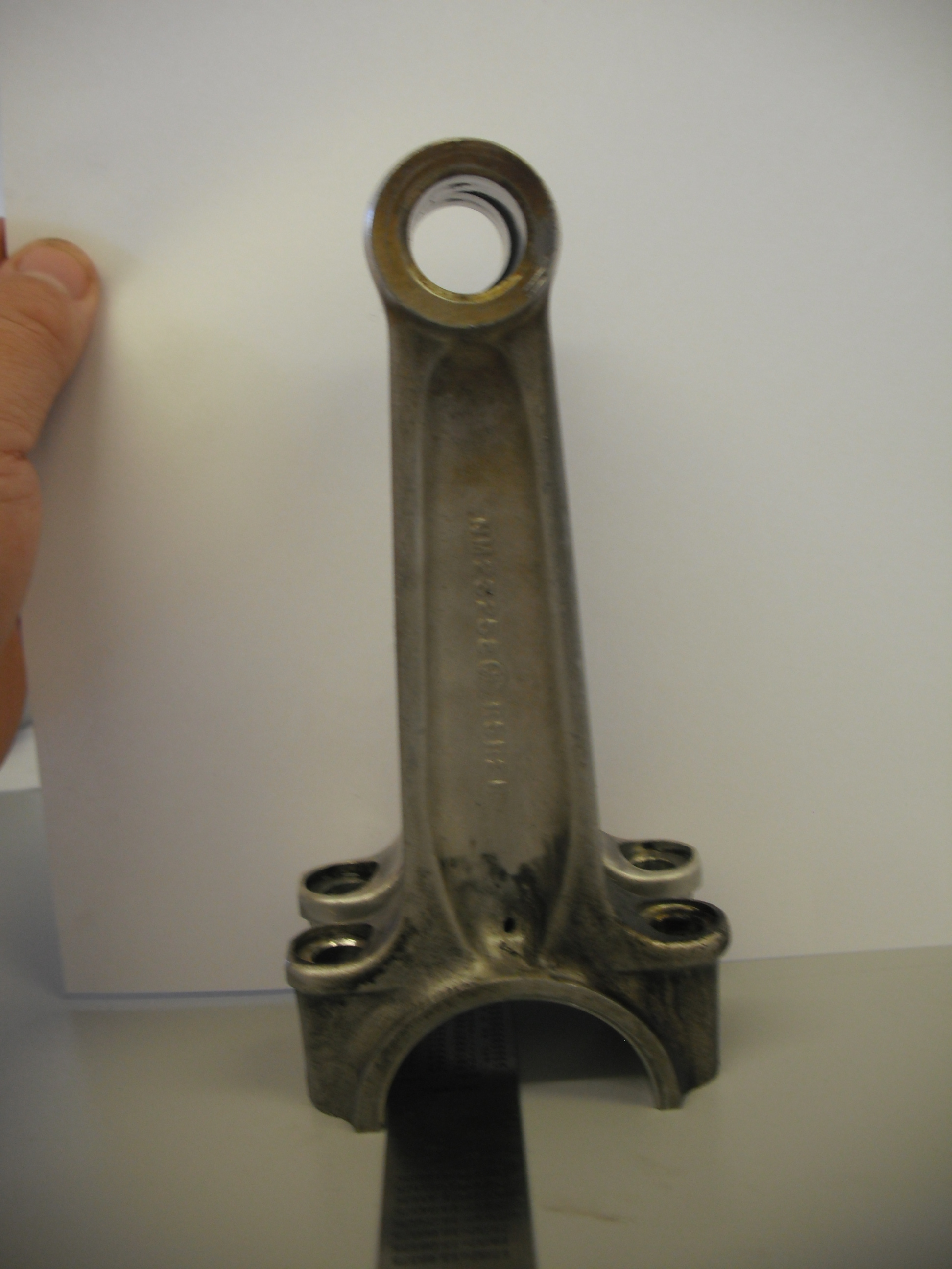
If anyone is wondering how the tolerances were abused back in 1975 see photo, the MK3 these came out of the crank was not that great either, even if it was lash up of crank parts when viewed from the top the journals were displaced which could be seen visually with the eye.
- Log in to post comments
Some may find viewing the…
Some may find viewing the photo above astonishing, but would I use them yes, along as the centres were correct. Sadly this is not the only MK3 that had been thrown together, the good news that when assembled with care and attention the MK3 as many above will confirm is an excellent Norton.
Something I have noticed is that many using a timing disc to set up use the left hand cylinder as it is easy and convenient as it is on the side that is being worked on, the manual says use the right cylinder. Having seen a few bolt up cranks on our jig here checked with DTI's I can see why, I would set up on the right cylinder and repeat on the left.
I have quite few scary photos of how the MK3 was bashed together, usually from unfinished parts.
- Log in to post comments


Just check the scale in the primary case is accurately set (using a timing disc and a piston stop or dial gauge) Then use that to strobe the engine as normal.
You would have to check the slot in the crank is accurate first (using the said timing disc) anyway as it could be anywhere.