
This seems a bit of an odd question and one i never thought I'd need to ask.
Until recently i owned a 1938 16H which that a modern solid state reg concealed inside the box of the old mechanical type.
I now have a 1935 M18. This seems implausible, but believe the wiring loom to be original having had 5 owners from 1935.
I can find no evidence of any type of reg being fitted, or any spare wires for its installation.
Some documents say that patents for automotive regulators came in around 1934.
Any knowledge would be very handy as all the electrics work and I don't want to stray from what looks original.
Thanks as always
Rodge West
Load resistors
- Log in to post comments
Third brush most likely
Third brush is hated by the dynamo repair men, just far too much like hard work to get it working and as far as the rider is concerned-bear this in mind. The idea is to move the third brush summer and winter to compensate for the amount of charge needed. The other way to control the charge is for the rider to watch the ammeter and adjust the charge accordingly. You wouldn't miss the stop lights from the car/bike in front as they never had them in those days.
90 year old wiring and no stop lights. Very original for the museum.
- Log in to post comments
3rd Brush dynamo
I believe that the AVR replaced the 3rd brush dynamo system in 1936/7.
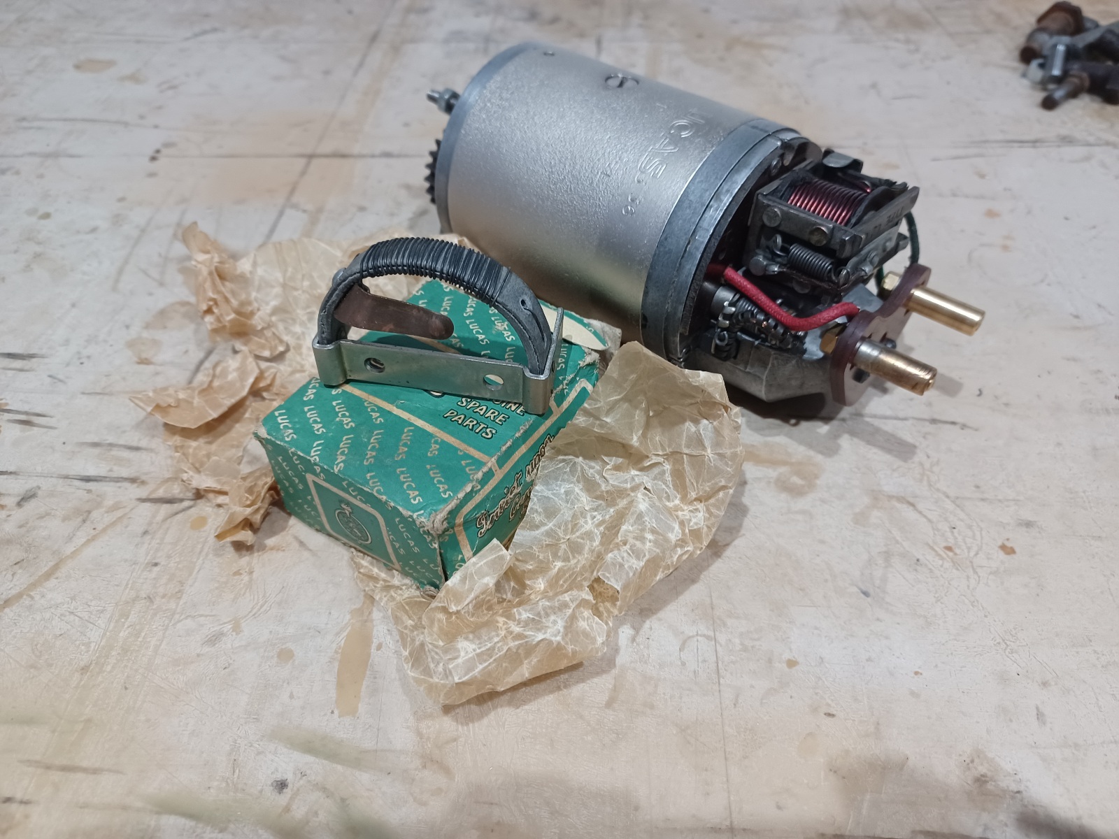
The 3rd brush dynamo was similar in appearance but had an enclosed cut out. The bearing caps were attached by 3 3ba screws at either end rather than by long draw bolts. It also ran on angular contact (magneto type) bearings rather tha ball race and bronze bush. Early ones had a fixed 3rd brush and later ones an adjustable type. This could be used for increased charge rate in winter. The dynamo had two connections, one wire going to the ammeter and one, marked F, going to the ligjt switch
The light switch that went with it was 4 posittion, with a large wire wound resistor mounted on the fixing bracket.
With the switch in the OFF position the F wire (the ground side of the field winding) is open circuit and the dynamo produces no output.
In the C posittion, the field winding is connected to earth but in series with the resistor. This limits the output of the dynamo in an attempt to prevent over charging.
In the H and L posittion, the resistance is disconnected and the field winding wire connected directly to ground, giving full dynamo output.
The 3rd brush dynamo can be converted to an AVR type by disconnecting the 3rd brush and cut out. The remaining field and brush connectors can be reconfigured to the match the AVR type.
- Log in to post comments
From what I remember, the 3…
From what I remember, the 3 brush dynamo was (up to a point) self-limiting with rising revs.
One of it's drawbacks was human nature. The high charge switch position was only meant to be used for a while, if the the battery was known to be low on charge, or maybe when stuck in slow traffic for a long time.
People couldn't resist (!) leaving it on high charge for far too long, or all the time, so batteries got boiled.
- Log in to post comments
CVC Fitment.
Norton listed Compensated Voltage Control in the 1937 brochure, which indicates that it was being included in production from at least September 1936.
It may well be that that it was available to order at a slightly earlier date. It certainly wasn't fitted to 1935 models.
- Log in to post comments
Agree with you Richard. My…
Agree with you Richard. My machine was a 35 built, 36 model and was converted to CVC with the resistor disconnected later in life.
- Log in to post comments
Pre CVC electrics
Many thanks Gents for all this information. I wad unaware of this type of dynamo having never owned a bike old enough.
- Log in to post comments
CVCs
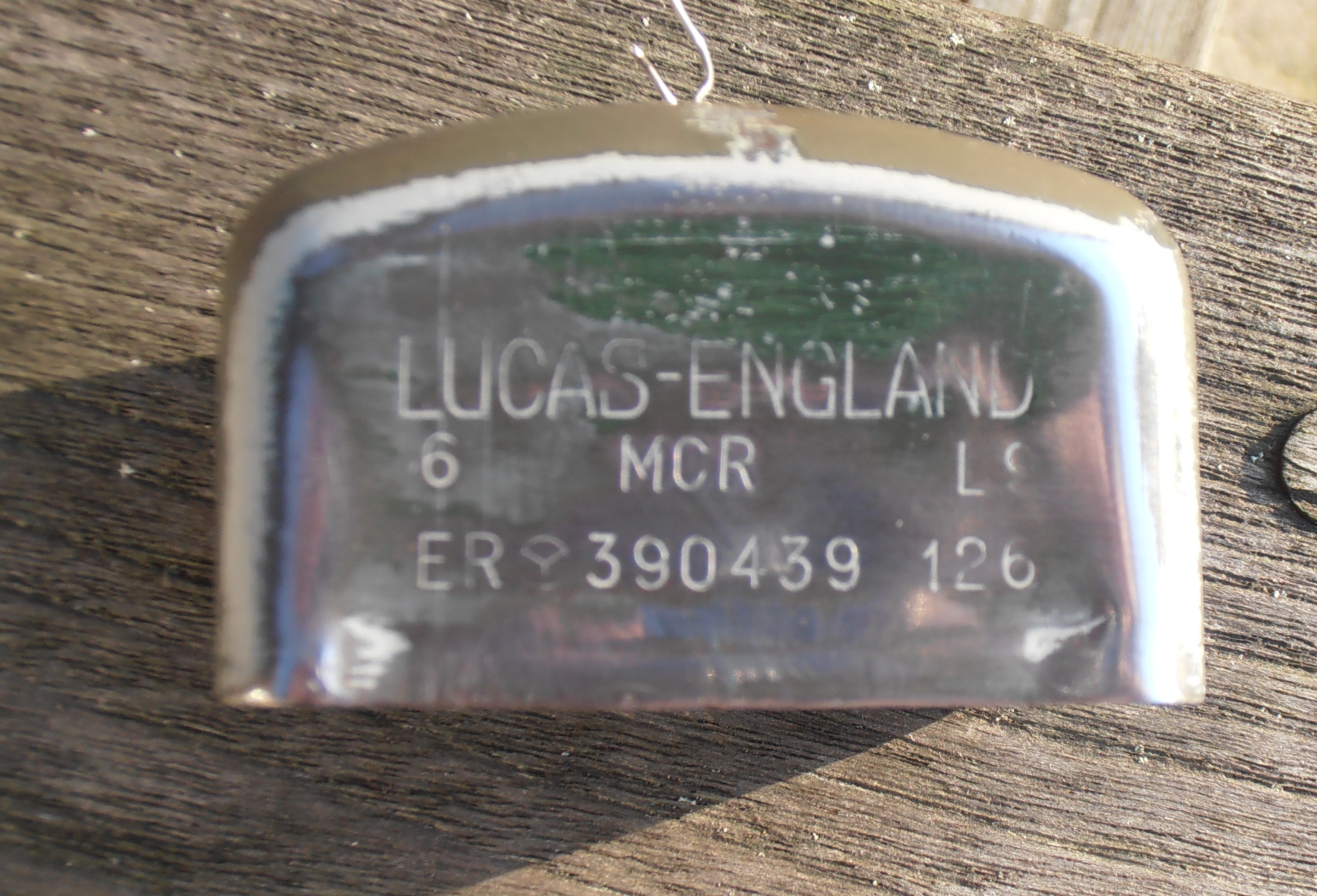
The earliest-dated CVC component that I have is a cover dated December 1936. For some reason Lucas didn't stamp a "decade" year during the 1930s so 12 6 was December 1936. 390439 was actually a Ni-Fe regulator, principally for WD machines. It wasn't actually Nickel-Iron, but actually a Ni-Cad. Real rivet-counters need the correct cover :-)
- Log in to post comments
For those that do not know.
The third brush item can be converted to two brush and a traditional type CVC fitted. I sell the electronic ones.
- Log in to post comments


No expert, but as I remember there were a couple of resistors on the back of the
light switch and a third brush on the comm . I believe the resistors acted like a dummy load when the lights were off and the third brush provided a reduced output when there was little need for charge ( full battery, lights off). I'm sure Alan will be along soon to put you (me) right. :-)
Forgot to mention, the experience I had was with a1935 machine which had been modified to take an MCR reg.