
I needed to take the timing cover off my 1972-built 750 Commando today. The head is a Combat but I know the bikes got superblend bearings and a standard cam. The breather is from the timing case via an elbow at top left corner, with a blanking plate on the crankcase.
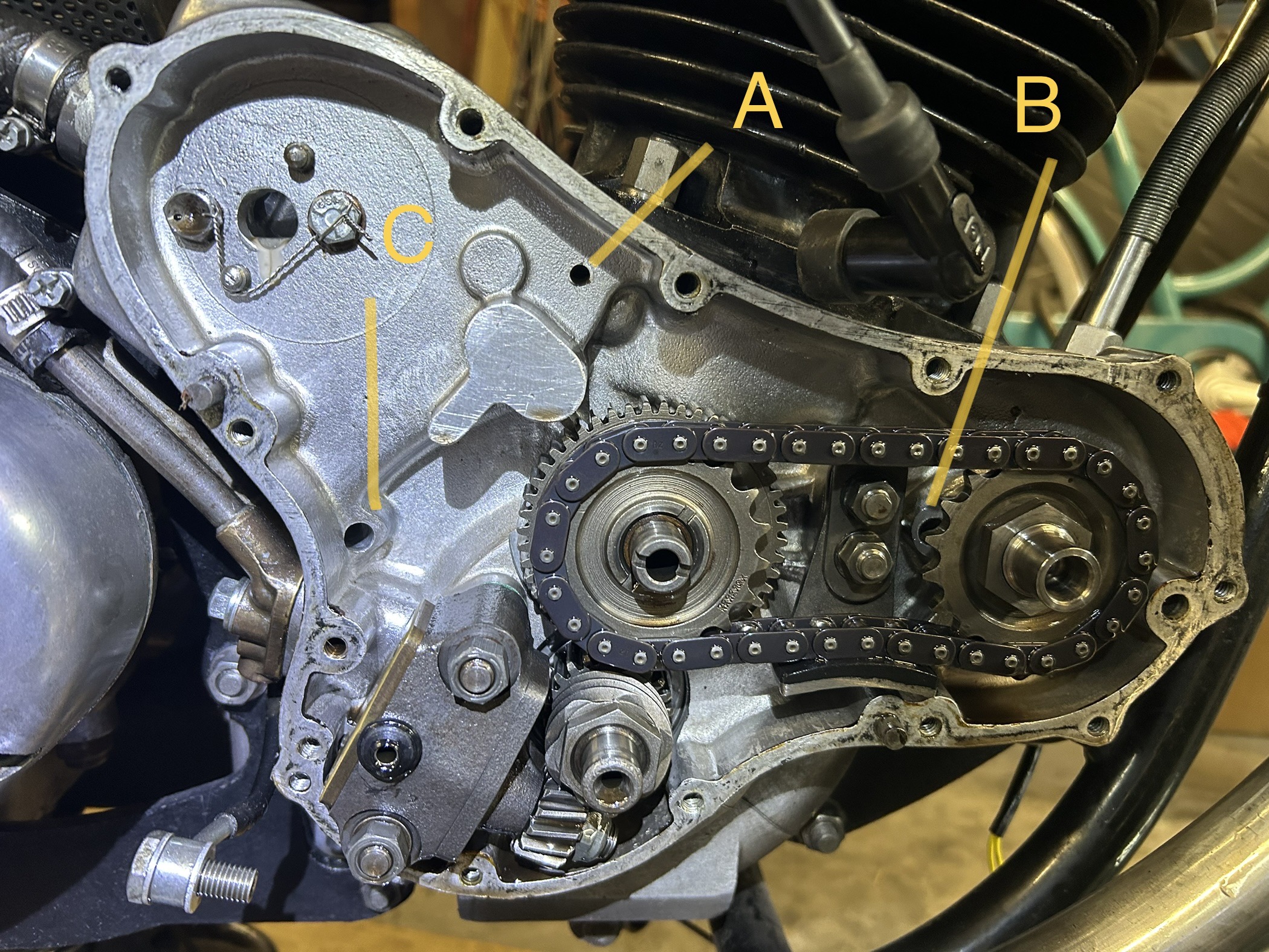
I’m wondering how the oil is managed in the timing case. The photo shows holes at A, B and C. I guess that B and C are into the crankcase and set the level in the timing case to keep the pump gears and timing chain lubricated. I assume this is why I got a big drop of tank oil level after rebuilding the engine which needed topping up and was then fairly stable (I’ve got a shut off valve in the oil feed line with an electrical interlock to guard against starting while closed, so I shouldn’t get a drop of oil tank level from flow through the pump clearances).
So this leaves hole A which I assume is to equalise the pressure between crankcase and timing case, with excess air (piston blow by) going out through the vent. I recently added a non-return valve to the vent line to lower the pressure in the crankcase and eradicate the last few irritating oil weeps). Hole A seems rather small to me.
Hopefully someone else can…
Hopefully someone else can confirm that. I am wondering how the timing case fills with oil to lubricate the chain and gears and I didn’t notice any hole low down from the crankcase or anything discharging into the timing case, so perhaps it is return flow from the head as you suggest…..
- Log in to post comments
As George said, hole A…
As George said, hole A drains oil from around the inlet valves. There is a drilling in the valve sping seat area that runs down thru the head to a corresponding drilling thru the barrel then into the crankcase and horizontally to the timing chest. The presence of this drain is why you must be careful not to break thru when working on the inlet ports, If this drain is blocked oil will pool around the inlet valves and the engine will smoke.
The timing chest is lubricated by oil spraying around from the pressure release valve in the timing cover. There is no shortage of oil in this area.
There's a diagram in the workshop manual that illustrates the lubrication - in colour!
- Log in to post comments
Morning Graham The oil in…
Morning Graham
The oil in the timing case gets back into the crank case past the timing gear/triangular washer and hole B and C. Hole A is the drain from the cylinder head. There is a diagram in the service notes (serialised in roadholder) that shows a modified hole pattern to drill in the crankcase to improve the cases breathing. Later engines were supplied like this.
Does your engine have the breather tower at the back of the crankcase?
- Log in to post comments
Thanks Peter, I didn’t spot…
Thanks Peter, I didn’t spot a path past the triangular washer and have not had to remove it (yet!)
- Log in to post comments
hole "B"
Hole B only exists in 200000 (combat breather) series. Its only function was to locate the cam thrust washer anti rotation tabs. The 062601 tab washers were potentially mechanically very toxic. Being late NHT thin wall cam bushes, replacement with regular 850 cam bushes is paramount. MK3 will also work but not as good as regular 850 bushes.
Breaking off the thrust washer tabs to allow continued use is extremely foolish by potentially allowing the thrust washer to rotate on the cases. The aluminum case should not be a wear surface!!!!
- Log in to post comments
spacer & baffle affecting oil control
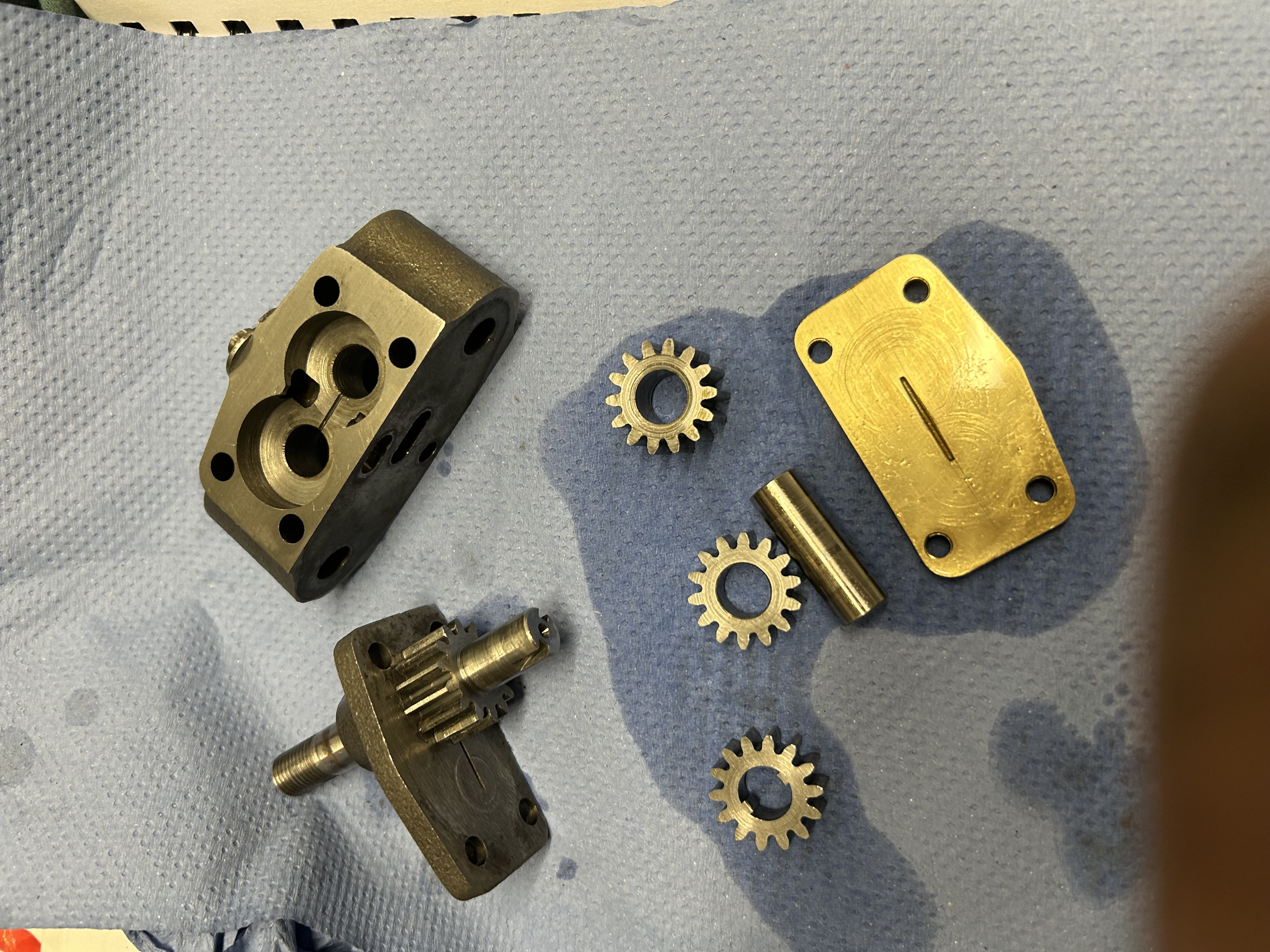
The thick triangle spacer,NMT2007-timing pinion back plate, is strictly to enable pinion gear removal tool engagement.
The thin tin washer behind the triangle is NMT2008-sealing washer. This washer is a close tolerance baffle that allows a bit of lubricating oil into the main bearing but prevents flooding. This is the main drain-down passage into the sump once the engine is shut down.
- Log in to post comments
Thanks all for your…
Thanks all for your explanations, makes sense now. I did look at the diagram in the workshop manual but the detail around the timing case area is not very clear in my black and white copy.
- Log in to post comments
More oil path knowledge needed!
Latest event in my Commando relationship….
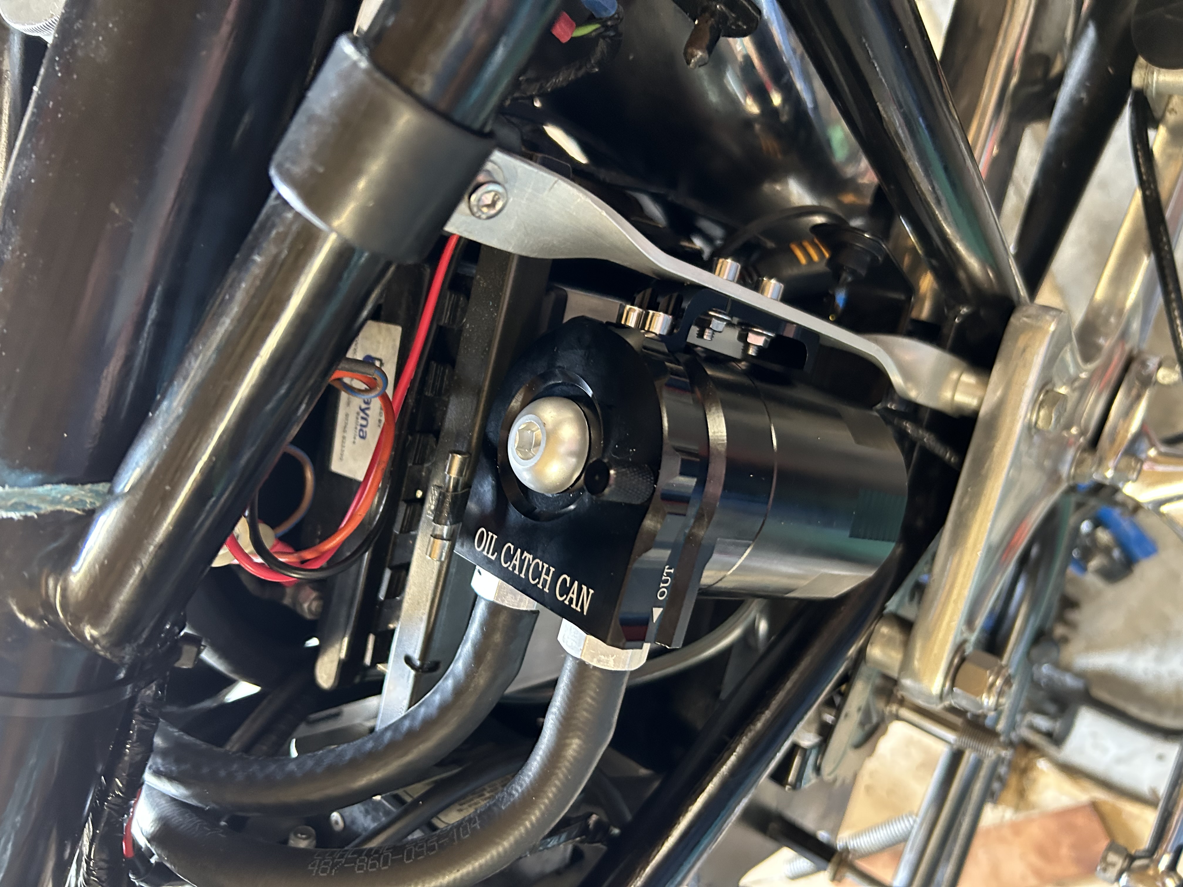
Oil in tank midway between the level marks. No oil in catch tank I fitted between oil tank and pancake filter breather connection after a few hundred miles of operation, only condensation, so catch tank removed…this might have been premature! Spirited riding yesterday including a motorway stint, bike ran great but a bit lumpy after the motorway and then stalled at a junction. Noticed a lot of oil in vicinity of the air filter and the level was below the dip stick. Slow ride home where I topped up the oil tank to lowest level mark….1.2 litres….this might have been premature!! Ride 10 miles today, stopped to find an oil slick on the road and oil everywhere else, dripping from the air filter: oil tank was full :-(
So it appears that after the high speed run the missing oil was lurking in the engine, I think in the timing case. What I do not understand is why, during the 30 minutes of slow running (<3000 rpm) after leaving the motorway, any excess oil in the timing case didn’t flow into the crankcase and get scavenged by the pump back to the oil tank.
Ref my photo earlier in this message thread, perhaps the crankcase holes are so small that it takes more than 30 minutes for the timing case level to return to ‘normal’ but the oil was hot and I find this hard to accept. Perhaps there was an adverse pressure differential with the PCV valve fitted in the crankcase breather hose which flows from the timing case, and positive pressure due to piston blow by in the crankcase was opposing oil flow from the timing case. Anyway, it seems that my Commando riding must be sedate in future :-(
- Log in to post comments
hello, Graham in the first…
hello, Graham
in the first photo looking at the oil pump pressure outlet. are those cracks around it. or is it how the camera has picked it up
barry
- Log in to post comments
Nothing that I noticed,…
Nothing that I noticed, including during subsequent strip of the pump to tighten the gear clearances
- Log in to post comments
I haven't thought through…
I haven't thought through the actual details of what must be happening, but I think your problem lies in the way your breather has been modified — namely that although the fitting on the back of the crankcase has been removed and blanked off, the necessary extra holes in the timing side crankcase have not been drilled.
See the AN information leaflet at https://andover-norton.co.uk/files/c39/Combat%20Mods.pdf, and compare its drawing with the photo that you posted. (Despite the leaflet's title this is applicable to all 1972 crankcases.)
Note that the full modification also includes changes to the oil-pump pick-up arrangements.
As a short-term measure I think you will have to reinstate the standard crankcase fitting (with or without PCV).
- Log in to post comments
Not so bad after all!
So now I have changed to a breather at the rear of the crankcase as per original 1972 bike and retained the PCV valve which I’d fitted in the line to the oil tank. The non-std breather connection to the rear of the timing chest has been blocked. Oil level is just above the low mark on the dipstick. I rode the bike on the motorway today for 10 miles at around 4200rpm/70ish mph, then pulled over at a junction and checked inside the oil tank filler: a little frothing but good return flow, no discernible flow from the breather and most importantly oil level unchanged! Which all makes me think that the original 1972 setup is fine for normal road use. My conclusion about the problem with the breather from the timing chest in combination with the PCV, which resulted in a large drop of oil tank level at motorway speeds, is that the small flow area (with original holes between timing chest and crankcase) restricts oil flow back to the crankcase and the pump scavenge port, more so when the PCV is lowering the mean pressure in the timing chest relative to that in the crankcase. As the oil level rises in the timing chest it tends to an even more adverse pressure difference because the holes to the crankcase are progressively being covered by the rising oil, impeding gas flow and pressure equalisation. Well that’s a theory which fits the symptoms on my bike anyway!
- Log in to post comments
Good news!
I've been following this discussion with special interest, because my Combat came with the crankcase outlet but also a outlet from the timing case (the two connected by a Y fitting) but no PCV.
On investigation it turned out that, like your bike, the crankcase drillings necessary to make the timing case breather operation had not been created. This set-up has been perfectly trouble-free, and hence I agree that the standard set-up is also likely to be fine for "sensible" road use. The reported problems seem to appear mainly in competition use.
Since I'm planning to convert my bike to your arrangement I am glad to hear that it works.
Did you retain the contents of the crankcase fitting? (They are a bit of foam plus perforated retaining plates; see items 59 and 50 in the diagram at https://andover-norton.co.uk/en/shop-drawing/34/engine-crankcases-crankcase-breather-tachometer-drive).
I ask because my provisional plan is to omit them and rely on the PCV alone.
Your theory about the timing-chest + PCV sounds plausible, incidentally.
- Log in to post comments
@Julian, there is foam in…
@Julian, there is foam in the breather now I and hadn’t thought to omit it. I guess it’s intended purpose is to reduce any oil that might be blown into the oil tank but with my combat arrangement that might actually help with scavenging! I would leave at least one perforated plate if it is retained without foam present, as a precaution against a foreign object passing into the crankcase, although an unlikely eventuality?
Regarding the Y, I did think of doing this as I am in possession of 2 breather ‘elbows’ and thought it would help equalise pressure across the chest-crankcase holes, but I want to retain the PCV which does appear beneficial for oil tightness and would have to be ‘above’ the Y, plus I want to encourage oil to return to the tank possibly via the breather line and a Y below the PCV might instead allow the oil to meander between chest and crankcase. It’s difficult to be confident about the actual effects, all I really know is my latest arrangement appears to have stopped a large quantity of oil pooling in the timing chest :-)
- Log in to post comments
10 miles at 4500rpm today:…
10 miles at 4500rpm today: same result as for 4200rpm reported above so all good. Fast enough for me on U.K. roads :-)
- Log in to post comments


Isn't hole A the oil drain from the inlet side of the rocker box? If so, is nothing to do with the breather.
Regards, George