
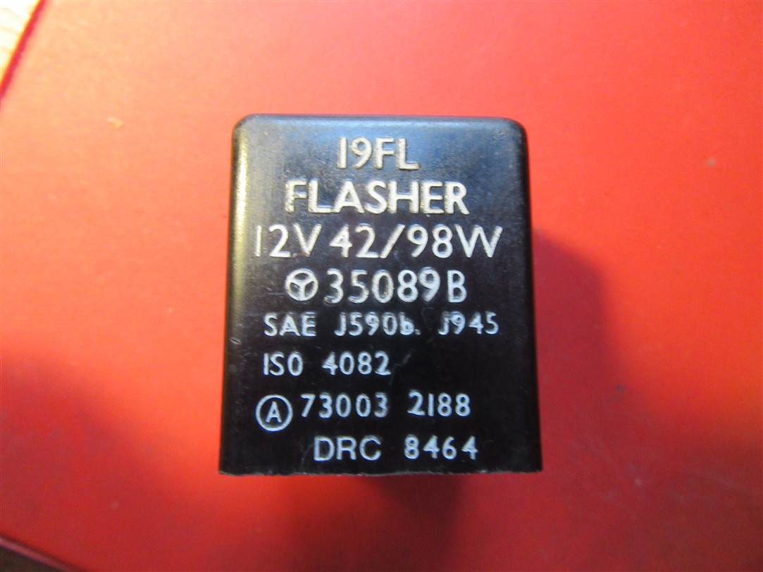
Sorry this is not specifically Norton but relates to the Triumph-Greeves which I am close to finishing. It has 12 volt positive earth electrics controlled by a Zener diode and solid state rectifier. I've fitted indicators but am not sure whether 2 pin flasher units - like this one https://www.racing-planet.co.uk/flasher-relay-digital-standard-without-beeper-p-137957-1.html - will work on positive earth. There are 2 terminals marked B and L. My thoughts are to attach B to the feed to the switch and L to the negative (live) feed but am unsure about whether this may destroy the flasher unit. Obviously this is the opposite way round to the normal negative earth layout. I have asked the supplier but with no response.
My other thought is to just have the indicator circuit negative earth as it's isolated from the rest of the system anyway.
Any thoughts?
Your thoughts look about…
- Log in to post comments
"B" = Battery. "L" = Lamps…
"B" = Battery.
"L" = Lamps.
If you have a multi meter with a diode test function use it to determine polarity.
- Log in to post comments
Thanks both.
Paul - Yes, but I imagine this assumes negative earth hence my question. I'm not sure how I'd use the meter with the flasher unit?
- Log in to post comments
I’m sure the person who…
I’m sure the person who wrote B for battery on it assumed that would be from the + side of the battery.
I wouldn’t be at all surprised if connecting B to a negative live and L to the lamps destroys the flasher unit immediately.
I use a similar (but orange coloured) flasher unit on my -ve earth bike. B is fed from a switched + live.
- Log in to post comments
Michael - but that is not…
Michael - but that is not what is being suggested.
Yes - it is safe to assume that B is Battery and L is lights. and 'normal' is negative earth so the B will be positive feed from the battery and the negative will be through the lights.
For positive earth, the B needs to go towards the lamps and the L towards the battery.
Thus the B is still getting the positive feed and the L is getting the Negative.
- Log in to post comments
Thanks Tony,
That's what I'm planning to try - and like Michael was thinking that connecting the wrong way may blow it up.. Having destroyed a dual output coil by leaving it switched on overnight I'd rather not destroy too much.....
My only thought is that the voltage seen by the B terminal after the electrons have struggled through the lamps may not be enough to operate it. But I always have plan B.
- Log in to post comments
I think the potential…
I think the potential difference across B & L will be the same.
- Log in to post comments
Yes, the electrons don’t…
Yes, the electrons don’t mind if they are going uphill or downhill.
- Log in to post comments
The supplier....
The supplier of this flasher is the correct company to contact, if they cannot tell you then the part is not fit for purpose and you get your money back. There is a great deal of these units available so find some one who understand what they are selling.
When these units had LUCAS written on them, and that meant something then these units were Bi metal strips and hence polarity was NOT an issue. IE you ignored polarity. It would be normal to expect there being an 'earth' with any modern Electronic unit. At this cost though we could be experimental and 'see what happens' if you connect it as you want. IF it fails then you return it for money back. But this 'orange' unit is 'digital' which infers it is Electronic, but this 'might not' be polarity conscious. Watching with interest.
- Log in to post comments
positive earth indicators
The original old aluminium bodied LUCAS FL 8 (I think) will work anyway round as Al says. mine is now 49 yrs old (had commando from new) with no probs, and they cost buttons to replace !!!!
- Log in to post comments
I think it should work. At …
I think it should work. At £3 it's worth a shot.
- Log in to post comments
Thanks again...
... I'm a bit under the weather with shingles at the moment but have ordered one of the units I references and will see what happens when I can brave the shed again. I did also find a 2 pin flasher unit from a car in my "spares" box which I opened up and see it's quite a complicated beast inside with a big coil and PCB which includes at least one capacitor. But have no idea whether it works......
Sadly most suppliers seem to have no idea what they are selling as you suggest Al. I did ask them the question, had a reply saying they would contact the manufacturer (which I thought was hopeful) but then nothing.
- Log in to post comments
The makers pile them high…
The makers pile them high and sell them cheap.
It is not worth their while to even care about a small number of eccentrics arsing around with antique bikes. Adapting it to non-standard conditions is your project, not the Manufacturer’s.
- Log in to post comments
If you use the diode…
If you use the diode function on a multi meter the electrons will only flow in one direction, same just using the continuity function.
You should also take note of whether the reading is telling you which polarity is flagged up +/-.
As the guys above are suggesting for three squid you can carry out all of our input as an experiment taking notes as you proceed and learn a great deal from the experience.
- Log in to post comments
As you have no idea what is…
As you have no idea what is inside, the diode test will tell you nothing.
just do as I said and swap the wires round.
- Log in to post comments
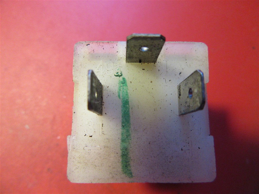
With a two pin flasher unit,…
With a two pin flasher unit, don’t get hung up on whether your bike is positive earth or negative earth.
The flasher pictured is plastic, with no connection to ground.
The B (battery) and L (lamp or load) probably doesn’t matter if the battery side is positive or negative.
As an example, take a look at the pic for a Commando.
Someone wanted to retrofit turn signals to his bike, so I split out the factory wiring for turn signals only - it makes it easier to work out.
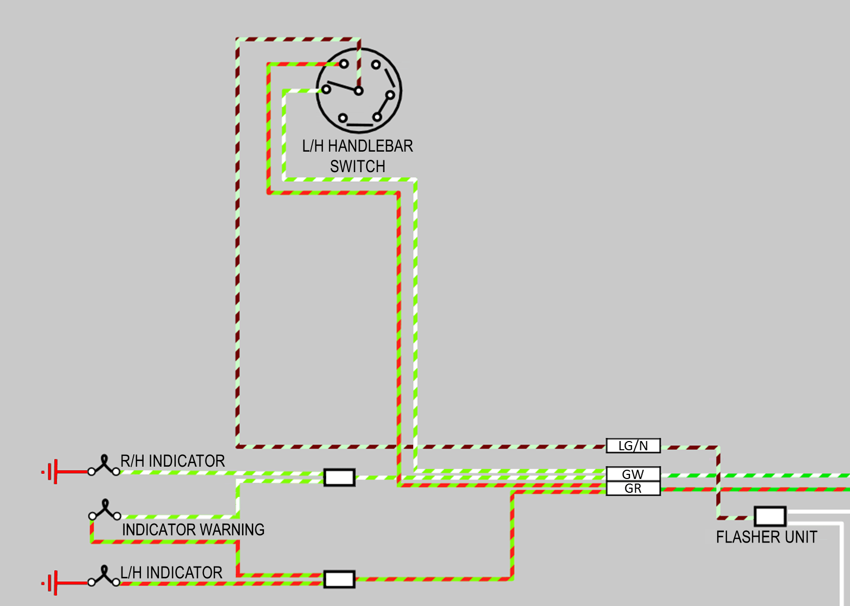
In this example, the W (white) cable that feeds the flasher unit is the ‘B’ terminal.
The LG/N (light green and brown) cable is the ‘L’ load terminals that goes off to the turn signal lamps via the left/right switch.
As a reminder, most of these have a wattage dependency - for example, the Lucas unit fitted to the Commando needs two 21 watt lamps as load.
If you don’t adhere to this requirement, the lamps will either flasher too fast, or they will stay on, prematurely shortening the life of the flasher unit.
- Log in to post comments
Thanks Grant...
... but that would assume the standard bimetallic flasher unit which is not polarity sensitive. Hopefully the one I've ordered will arrive today so will try the "reverse connection" layout health permitting.
- Log in to post comments
Success....
.. the flasher arrived this morning and I connected it with B to the indicator switch input and L to the live (negative) supply. It worked very well so I'll not bother trying it reversed.
Thanks for all helpful input.
- Log in to post comments
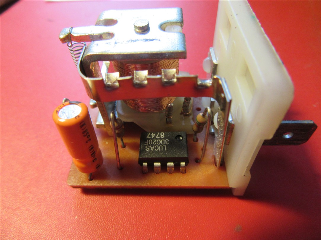
This is my other unit...
... genuine original Lucas, from a Land Rover Discovery if I remember correctly. The 3 pins left to right are marked 31-, 49a and 49+
- Log in to post comments
Now that they’re working,…
Now that they’re working, don’t forget to cancel them after the turn.
- Log in to post comments
Ian.....
Ian, you said your flasher was two pins!! BUT it is three!! Also this is real electronics, Integrated Circuit (chip-IC) electrolytic capacitor. They all need the electricity to be the 'right way round' Or there is 'trouble in camp'. Ian by the way that 'big coil' is a relay. On their own a relay does not have any polarity, but they are suseptable to Voltage and the voltage must be DC. Some times you find a relay for use in a modern cars becomes polarity conscious as it has a diode fitted.
- Log in to post comments
Thanks Al..
.. this was the one I dragged out of electrical spares pile just wondering if I could get it to work. But probaly not reading your comment. It does seem very complicated to perform a simple function.
- Log in to post comments
Ian not so
t does seem very complicated to perform a simple function. With the original Lucas Bimetal strip flasher they were very cheap/simple. The flasher rate was quite variable, the MOT/safety requirements showing this with variable Flasher rate. Also these basic units were very dependant on lamp load 2X21W in our case. This would mean that the loss of a lamp or extra lamps would stop the flash rate. So adding a trailer or 4X flasher would not work-you needed another flasher unit. The larger unit seen above will be very constant on its flash rate (due to having ICs) and it should handle extra flasher lamps with the relay. ie 4X, but it will be polarity dependant.
- Log in to post comments


Your thoughts look about right.