
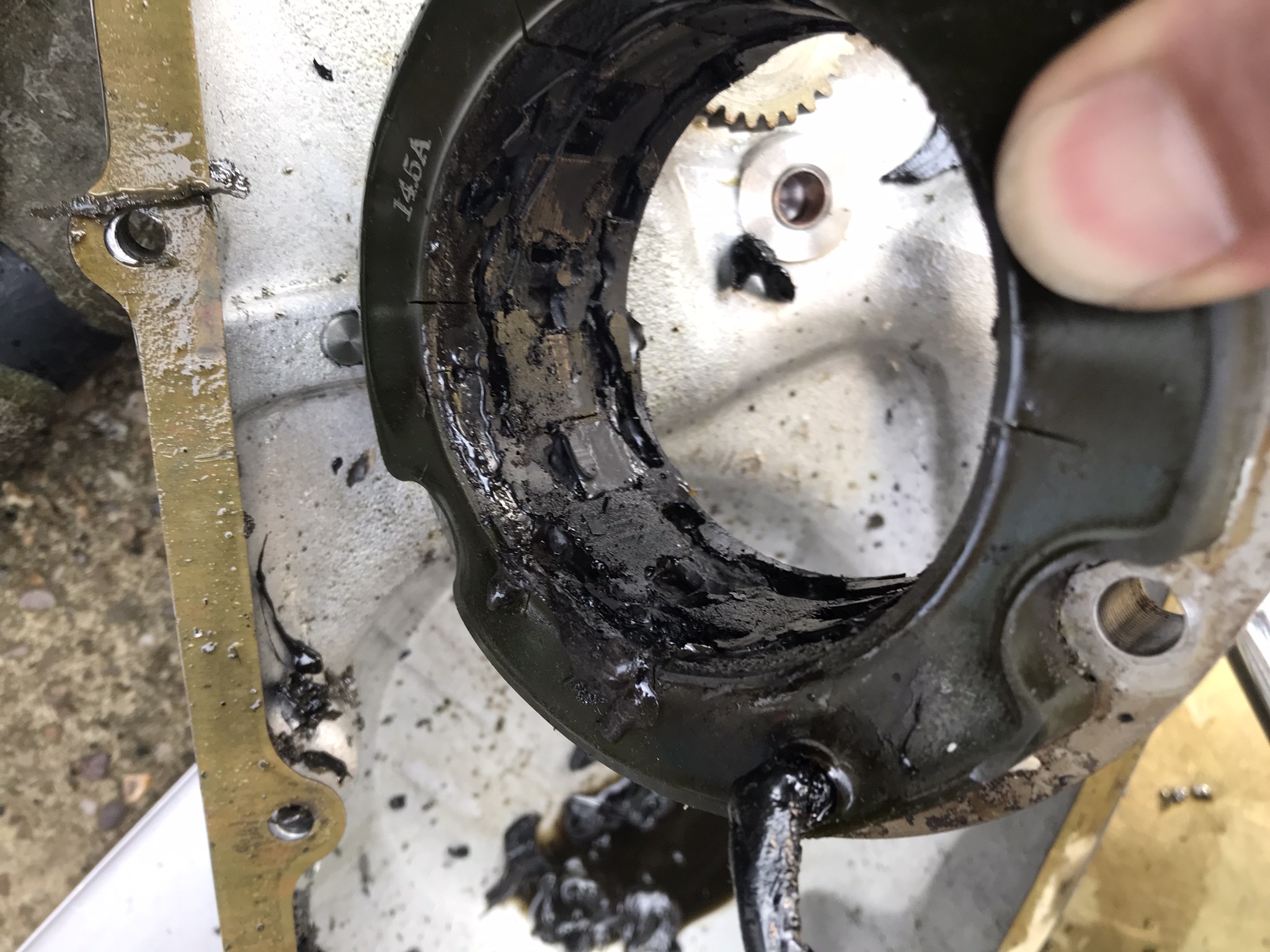
I cleaned and reassembled my new (old) crankshaft today.
Just for the hell of it I put it between centres on the lathe and attached a dial gauge to see if there was any runout. Measuring onto the main bearing journals I got 10 thou on the timing side and 18 thou on the alternator side.
Is this excessive? What are the limits?
I appreciate this is not indicative of the runout between the main bearings when the crank is installed, but I'm worried nonetheless and would appreciate your input.
Cheers
Matt
1972 750 Commando 207532
Knackered centres?
- Log in to post comments
Put the crank on a pair of…
Put the crank on a pair of vee blocks, running on either the shafts themselves or the roller bearings if still fitted. That way you get a better, more accurate picture of how the crank is aligned.
- Log in to post comments
On Vee blocks
Thanks for your comments.
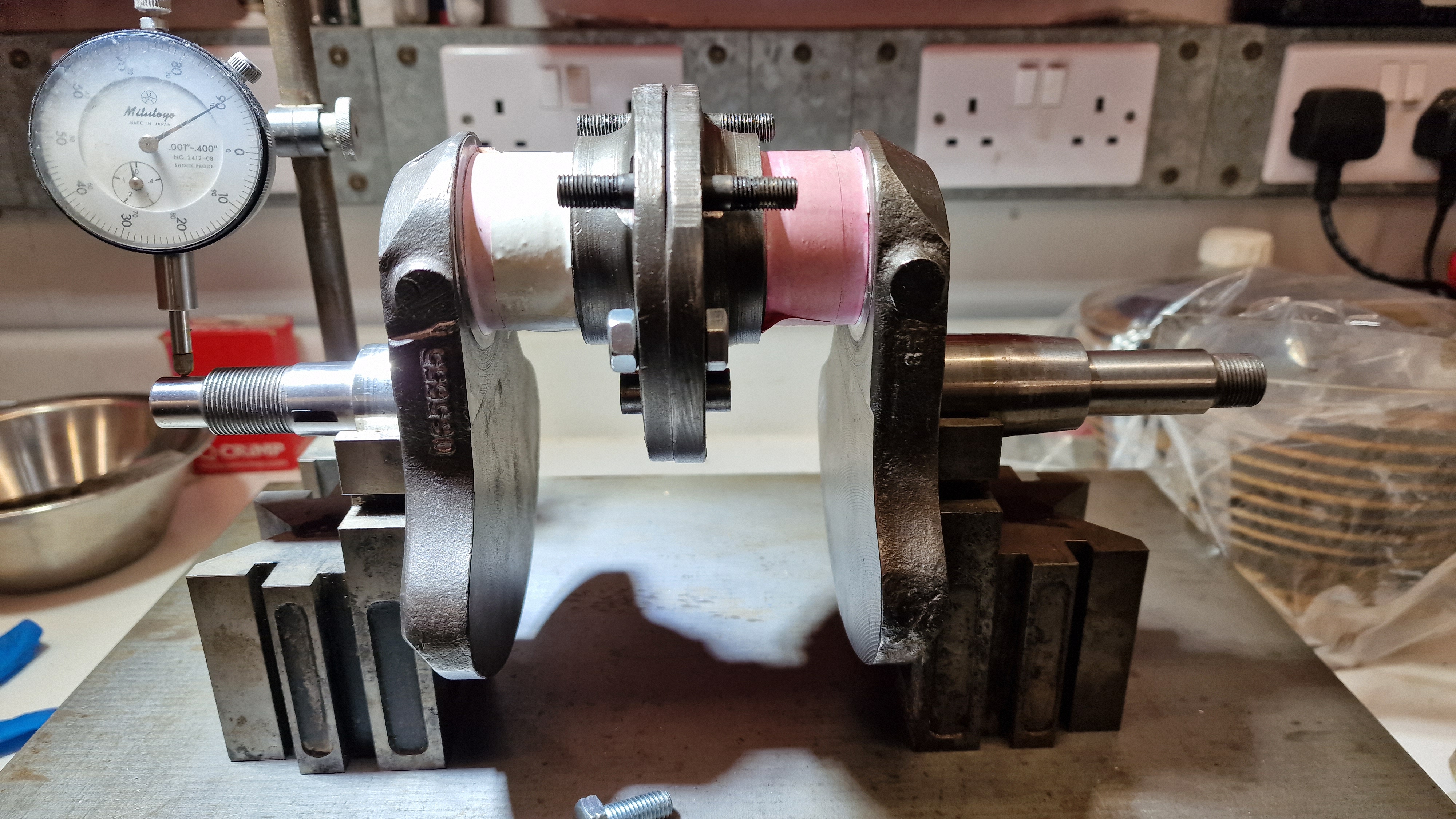
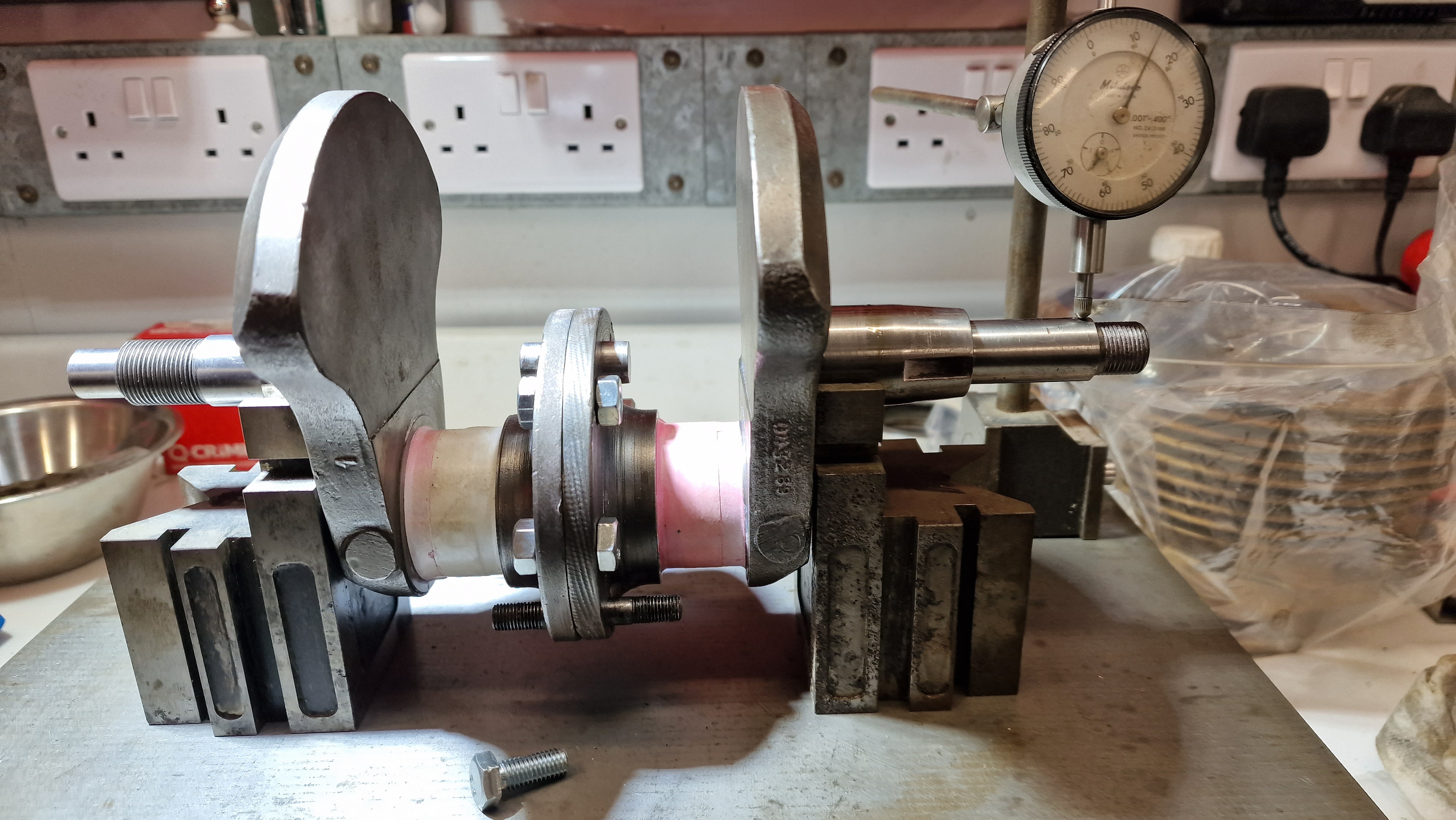
As suggested I put the crank (sitting on the main bearing journals) on Vee blocks and a surface plate. I have 15 thou runout on the primary side, (as measured at the end of the shaft just past the key slot) and 10 thou on the timing side. (see attached images).
To be sure, I disassembled the crank and bolted it back together again, minus the flywheel, with the same result. I conclude therefore that the crankshaft is bent or possibly the mating faces are not machined at right angles to the shaft axis. The bend is on the TDC/BDC plane.
Should I be concerned or is this acceptable?
- Log in to post comments
Ive just checked a customers…
Ive just checked a customers 850 bottom end with 17k miles on it. 3 thou total runout at the Primary drive end. Are the crank halves a matched pair? Do you know if your crank has suffered some trauma in the past? If not, i would be tempted to believe that this is a good example of somewhat questionable manufacture when it was made. To get the crank into better alignment, start by addressing the flange faces to get the shaft ends as close as possible to zero runout. Then regrind the crank to get the big end journals parallel.
I remember reading about the Rawlings Baker 850 Commando that at the time was the fastest 'production' road bike on the drag strip. The crank on that engine had the crank cheek flanges scraped and blued to get it as rigid and true as possible.
- Log in to post comments
I thought that the crank…
I thought that the crank connection had two of the six (?) holes reamed to size for fitted dowel bolts which should be fitted first. Is that correct? If so, it would be easy to assembled incorrectly. And if a bolt is driven in, it's easy to get unseen swarf between the faces. Perhaps it needs taking apart and reassembling with more care than the PO?
It would originally have been turned on a lathe after assembly, so it's difficult to imagine how it could have any measurable eccentricity between the machined parts.
- Log in to post comments
Crank supplied in bits.
Thanks for the comments.
The crank was bought secondhand (last week) to replace the original which had drive side taper and keyway damaged beyond repair (see my earlier post re. this). The crank was supplied in 3 pieces with parts for reassembly. I'm not sure if the parts were manufactured together. The flywheel is certainly later. Nonetheless the runout is there if the two cranks are bolted together without the flywheel. The parts are clean and free of swarf.
I shall contact the supplier to arrange for return and refund (or repair). It is a well known supplier so I might get a result, otherwise I shall try to temporarily correct the runout using a shim or a feeler gauge to see what machining is required. I shall name and shame if the response is inadequate.
My lathe is not big enough to hold the crank halves eccentrically so I'll have to farm it out. Any suggestions?
- Log in to post comments
Naming and shaming! Hmm. I'd…
Naming and shaming! Hmm. I'd like to see you get away with that on this site!
Did you take a runout reading whilst set up between the case halves, and does the crank spin freely once all is bolted up.
Take readings from close to the crankcase halves on the shafts and then gradually outwards this way it may indicate where the run out starts and therefore give you an idea as to "Trauma" or it came out of the machine shop in this condition.
I would be inclined to suspect the latter as AMC machining left a lot to be desired at times.
Can you set the shafts up individually in the lathe chuck to enable a clock gauge to have it run true and then set the gauge up against the faces that fit up to the flywheel to see if your problem lies with these faces not machined square to the shaft.
This way you will know where the run out originates from.
I can't remember if the crankpin halves have a centre in the flywheel faces as this could help with the setting up if things are tight at the chuck end.
It may well be that this crank has been run in the past in this state without any problems.
Do the big end journals show any witness marks to suggest the run out is causing uneven contact?.
If the runout was machined in, the journals would have been ground to suit it by default.
Make of this what you will.
- Log in to post comments
More thoughts on the crankshaft
Thanks for your comments Paul Griffiths.
After having slept on the problem I'm pretty much in the same mind as you on all counts.
1) Apart from the runout the crank is in very good condition, if I sent it back and got a refund I'd be hard pushed to find another as good.
2) I have not yet put it in the cases as I'm loath to push the bearing inners on (because I don't have a puller to get them off again) but as you suggest I think the time has come. I'm probably going to have to adjust the end float anyway.
3) I'm can't clock the halves in the lathe because the four jaw chuck is not big enough to hold such a large eccentric lump. The protruding shaft is the big problem. I'm going to ring round local engineers to see if they can clock and true the halves.
- Log in to post comments
Matthew. …
Matthew.
Another consideration of importance is the alternator rotor/stator clearance of .008" all the way round for the air gap. Catastrophic failures have occurred if this is not addressed due to the rotor creating friction with the stator to then grab it tightly enough to seize the engine.
If it was my choice, I'd go for the engineering shop route and find out how competent they are before you entrust the job to them.
As a matter of interest did you check the run out on the first crank that you posted? Maybe this could give you some idea as to what to expect re run out.
A chap on the Access Norton site has found that his crank has a run out of .007" at the rotor end without any apparent issues.
Rgds.
Paul.
- Log in to post comments
Is the lathe large enough to…
Is the lathe large enough to remove the chuck, replace it with a centre, and set it up fully assembled between centres? Of course there's no way of knowing if any crank centres were used as the reference point for final machining of the entire assembly.
- Log in to post comments
Hi Matthew, I have just…
Hi Matthew,
I have just searched the forum, back to when I asked about runout 10 years ago. Looks like I had 3 thou runout possibly due to a belt failure. When I put the rotor on and clocked it the reading went up to 10 thou which had destroyed a new stator, hence my enquiry. I had to cut a thin shim to put between the shaft and rotor to true it up. Rather annoyingly, I’ve just had the same thing happen on a different bike, again another new stator destroyed! Shimmed this one again now and sanded the stator inside diameter for more clearance. If you ever get chance to buy shares in a stator manufacturing company then take it! You would have thought I’d learnt a lesson but I’ve had a lot of sleeps in the last 10 years!
Best regards, Al.
- Log in to post comments
A tip in Norman Whites,…
A tip in Norman Whites, Norton Commando Restoration Manual advocating machining the stator retaining bolts to allow more jiggle room whilst air gapping the rotor stator set up.
By machining the bolts to the core diameter of the threads should give sufficient movement to gain enough air gap between the components.
- Log in to post comments
Air gap
Cant add anything re. your crank, but for the alternator airgap, Hitchcock motorcycles (the Enfield people) sell a useful item, that is very easy to make yourself.
Cut some paper just a bit shorter than the circumference of the rotor and laminate it!
The one I bought before seeing how simple it is, is just that- an 8-9 thou thick plastic coated piece of paper 3" wide and sround 9" long. Wrap around rotor, slide on stator and nip it up, pull out plastic and hey presto, perfect clearance all round. Worked very well for me earlier this year.
Hope that you get it sorted,
George
- Log in to post comments
Just a thought. Have you…
Just a thought.
Have you checked the runout with the crank assembled onto the flywheel?
- Log in to post comments
I use a strip...
... cut from a screenwash bottle which is about .008" thick to centralise the stator. Works for me (and of course is very cheap!)
- Log in to post comments


Inspect the centre holes carefully, probably have light damage throwing things out.