
My '56 ES2 has floppy front footrests, the castellations look very worn - does anyone have suggestions on a remedy please ?
A new small triangular fil…
- Log in to post comments
I?m now restoring a Model…
I?m now restoring a Model 18 1947, and incidentally I was yesterday by turning a castellated insert for the footrests, which are badly worn.
For that purpose, I turned on my lathe first a special device to turn an insert for my Panther M35 1953, which has 20 teeth and is also wider, so, for the Norton which has 16 teeth, I turned another 16 hole disc. If not wrong, the angle of the depression/protrusion of the teeth is around 9?40?.
If of interest not only for you, I can try to make more inserts, but before I will send a picture (tomorrow).
Let me know if you have interest.
Hans from Chile.
- Log in to post comments
Alternatively, new castell…
Alternatively, new castellations are available to buy and can be grafted on.
- Log in to post comments
Thanks both. Chris where c…
Thanks both. Chris where can these castellations be sourced?
- Log in to post comments
Attached an insert for the…
Attached an insert for the footrest. This one is for the left hand, or nearside. As my footrest supports are badly worn, the measures I took from them may be slightly wrong.
If anyone can tell me the exact measures of both the left and right support, with the whole integrated parts, i.e. tube, washer and insert itself, I would be very grateful, being useful for those who need to repair a footrest.
As I also own a M50 1959, the insert for the Model 18 is also available for the M50, which in my case are also worn. Anyways, the right side insert is different, having cross tabs joining a slots in the engine plates.
Finally, I tried to attach another photograph, with no result. The link below selecting file, doesn?t work properly, because instead adding it, it clears the former selected.
For the moment, the next photograph will be attached without text.
Attachments
footrest-insert-1-pptx
- Log in to post comments
Attached the second photog…
Attached the second photograph. Please, correct me the measures, if wrong.
Attachments
footrest-insert-2-pptx
- Log in to post comments
Previously stuart_munroe w…
Previously stuart_munroe wrote:
Where are these obtained and how do they fit?
The one of Chris mentioned or mine?
- Log in to post comments
Previously Hans Eberlein w…
Previously Hans Eberlein wrote:
Previously stuart_munroe wrote:
Where are these obtained and how do they fit?
The one of Chris mentioned or mine?
Either please!
- Log in to post comments
Hi Stuart, As mentioned be…
Hi Stuart,
As mentioned before, I need the exact measures of both footrests, because the ones of my Norton 18 are bent, re-welded and perhaps, shortened.
With a bit of patience, I could determine the measures of the nearside footrest, by the given distance of the left crankcase and the stud attached to the rear engine plate, this for the support of the inner chaincase to the welded large washer. The outer chaincase can also determine the lenght of the tube, where the insert should be welded to. This latter I made with nearly correct measures, remaining to turn the recess for the tube, wich diameter I don?t know.
The same for the right hand footrest: I don?t know the total lenght, including the insert welded to it. The insert itself was poorly re-welded, and I suspect the tube is too short, because the long rod is about 1 inch too long. I need also the lenght of the rod, to be sure it is correct.
Once solved all the measurements I need, I will be able to make the inserts, for the moment, and eventually the whole supports.
Let me know what do you think about.
- Log in to post comments
You could look at a l.h.s.…
You could look at a l.h.s. serration piece from RGM, also a r.h.s. serration piece from RGM.
- Log in to post comments
This converstation might e…
This converstation might explain why my LH footrest tube is too short to get the full thickness standard Norton nut on top of the chaincase. I thought maybe the rubberband was the wrong one but maybe someone has filed too much off it to replace those serrations.So the length of my LH side is just a bit too short forbeing long the band pllus case plus nut plus a few spare threads. And because the serrations splay out from the centre they aren't easy to file as well as Hans has cut his.
- Log in to post comments
I waited for the measures…
I waited for the measures of the footrest support, without reply, so, I tried to get it by turning the parts in my lathe.
I will share more photographs of the support, but I don?t know how to do to attach a serial of photographs, instead of posting one to one.
I wait for this instruction.
Attachments
img_3627-jpg
- Log in to post comments
Previously robert_tuck wro…
Previously robert_tuck wrote:
A new small triangular file, a stout vice and an hours light labour .
Sorry, but as you can see at the photograph attached, the file should be a square one, The shape of the serration has a 90? figure.
Attachments
img_3636-jpg
- Log in to post comments
What RGM offers is a R.H.…
What RGM offers is a R.H. serration insert 16772 suitable for the tubes welded to the engine plates; other version is an also R.H. serration insert 18268which includes a tabs fitted to the latter engine plates provided with slots.
RGM also offers the whole L.H. footrest 20936 suitable for the slotted engine plates. I don?t know if the length is the same as the the welded ones (I can see it by taking off the chaincase of my M50 1959), but I doubt.
No other offers I saw at the RGM website. But, how about if the serration or the thread of the L.H. footrest are damaged?
Not having received any information or help, I decided to develop the footrests for my 18 1947, both badly worn.
The result, after having turned the parts on my lathe are very interesting, in which the serration inserts can be welded by simply turn off the damaged section and weld again.
If of interest for the owners, I can post a drawing, containing all the measures for a self made with a lathe, and eventually make some for the owners.
Anyways, you should take in mind that due the lack of the original measures, I made them considering the length of the spindle of 13".
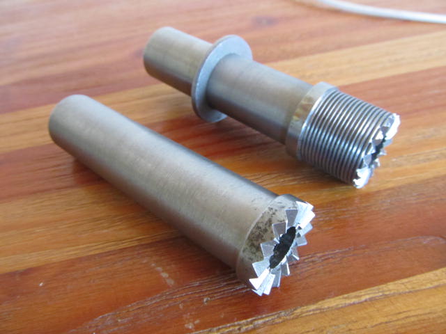
Attached, a photograph of the footrests needing only to be welded and another of the footrests with the inserts taken apart
Attachments
img_3637.jpg
img_3642-jpg
- Log in to post comments
Thanks Hans those pictures…
Thanks Hans those pictures have been very helpful. Unfortunately mine are so badly damaged any measurements would have been of no relevance. Another project for the winter!
- Log in to post comments
Attached a drawing of the…
Attached a drawing of the L.H. footrest support which I have developed not on the desk but with the bike near to the lathe, striping off the chaincase many times to achieve the distances to the inner chaincase, outer chaincase, and the nut against the latter.
The main part is not a tube. It was turned from a solid bar, and provided with an extra shoulder at the back of the washer for better alignment.
If the footrest itself is too damaged, the new insert of the support would be enough to hold both parts together.
Mine are half way worn, so, as it is not possible to reshape in the lathe due the long arm, I will reshape the teeth with a square file, putting it in a vice and filing in that manner, always to the centre of the section in an angle that the under side of the file passes imaginary at a level between the lower and the upper side of the tooth in the centre of the section. Did you understand the explanation? If not, tell me and I will try to send a sketch.
Further I will post a drawing of the R.H. footrest support.
Attachments
footrest-support-lh-jpg
- Log in to post comments


A new small triangular file, a stout vice and an hours light labour .