
Hi all,
I've been a member for a year now and enjoyed reading lots of posts from others about what they have done and the problems they have overcome. So I thought it was time I returned the compliment and shared some of what I have been up to lately.
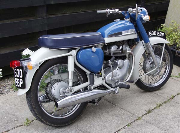
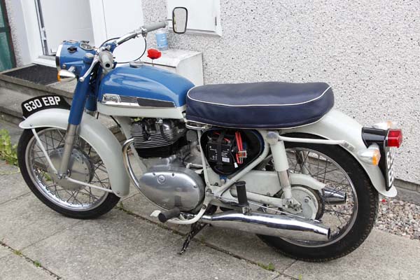
Just over a year ago I bought a 1961 Navigator which was a runner and in good comdition so didn't NEED much doing to it. But as I got it to give me something to do to keep ME in good condition I decided to try and bring it up to more modern standards without changing the look too much. I think I have managed that fairly well, but that is for you to decide, and I'm sure you will tell me if I haven't.
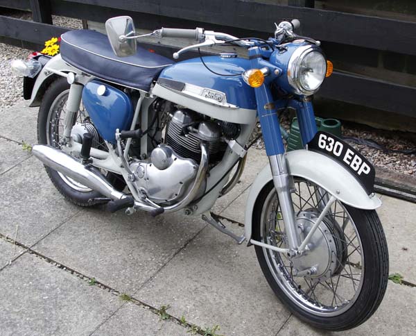
I have rewired to 12vneg earth, fitted Boyer Electronic Ignition and indicators plus a few other alterations. Also added an external screw-on oil filter and ball valve in the oil supply line which has a microswitch to isolate the ignition unless the valve is FULLY open.
I will post some details of the work done in the next few days, here are a couple pics for now.
Thanks,
Stan
Thanks Uli
That size and resolution won't show the small chips etc so it looks better than in real life,
Stan
- Log in to post comments
You bike look great, I have…
You bike look great, I have done the same mods but unfortunately my Navigator was a basket
case. Where did you fit the oil filter?
- Log in to post comments
Oil filter
Thanks Steven,
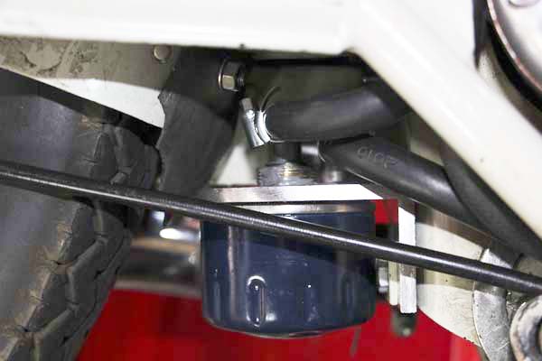
It is fitted on the back of the central frame just in front of the mudguard. I couldn't find an adaptor with 3/4"UNF threads for my stock of Crosland filters so had to make my own.
Stan
- Log in to post comments
1st update of work done
Hi Again,
So here's the first update of the changes I have made to this bike.
Engine - the iternals have not been touched as it runs well enough with no evidence of any problems, and is oil tight. The sump plate was distorted and the gause filter in poor state so I got a new filter and as the club spares had the alloy sump plate I fitted one, and it now looks better too, even if you have to crawl down to see it.
Gearbox - as the box had very little oil in it and reading about the layshaft bush problems it was obvious that it would need to be checked. Sure enough the bush was able to be removed but as it had no signs of having been rotating and the oilway was still aligned I assumed it had been caught just in time. So I refitted it with Loctite stud and bearing fit, checked 24 hrs later and it was secure and the rest of the box was good I reassembled it. After a dry fit without a gasket I just used Loctite 5920 sealer and this is working out fine. One thing I have found is that if possible don't use a gasket if the faces are good, with a gasket you have to seal four faces, without one there is only two. I have replaced the gearbox and primary cover screws with cap screws. So they are oil tight now.
Breather - I adapted a Yamaha YZF R 125 EGR exhaust valve and fitted it in the breather hose into the oil tank. The tank breather has been fed into a catch bottle under the seat so I can moniter this, the reason I wanted an easy way to remove/refit the seat.
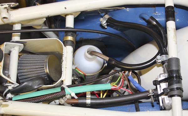
Air cleaner - fitted a cone style air filter, it was quite hard to get it in but once there is out of the way.
Crosland 659 screw-on external oil filter - I have 10 of them from previous bikes and as they have 3/4" x 16tpi UNF thread I had to make the filter adaptor. It is fitted onto the back of the central frame just in front of the mudguard, I fitted a rubber screen to the mudguard fixings to prevent any splash getting onto the filter assembly. Note, all the ones sold now are M16 metric threads. See previous post.
Oil tap - now I know lots of people don't like them but . . . this engine suffers from wet sumping so I have fitted a tap. My main argument for this is something not often mentioned when this is discussed.
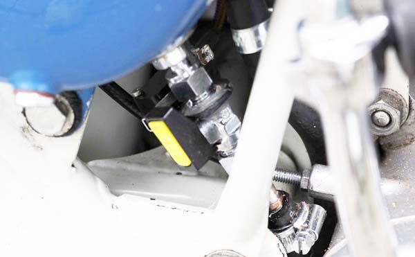
If the oil tank has drained, the next time the engine is started there is NO OIL SUPPLY to the bigend bearings for the length of time taken for oil to be returned to the tank, drained down to the pump and then pushed out to the bearings at a reasonable pressure. The most wear is caused when the engine is first started and any delay in supply to the bigends will only increase this wear - think about it, that is NOT GOOD.
So I got a plumbers full flow ball valve with compression fittings and it is fitted onto the outlet stub from the tank filter, and onto a short length of commercial brake pipe the same diameter. I then made up a bracket for a microswitch which is secured to the tap body with JB Weld. It is wired into the feed to the ignition so that the ignition is isolated unless the tap is FULLY open - and it works.
Stan
- Log in to post comments
Next update
Back Again,
So here's the next list of changes to this bike.
Amal 534 type ball ended levers - I fitted a set ot these which have 7/8" centres and also adjusters, so I made up new clutch and front brake cables to suit. The clutch now feels and works a lot better.
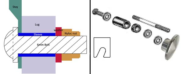
Roadholders - as there was a slight leak from the RH damper bolt I stripped them down and cleaned them out, all looked and felt ok. As they were in bits I fitted a sleeve over the four lower damper oil holes on both legs and drilled a 1/8" hole just above the taper. The threads for the mudguard stays had been stripped earlier and odd bolts fitted so I sorted out a system to use M6 stainless hex socket flange headed Allen bolts with sleeves to take up the space in the 5/16" holes and align the ends of the stays. Looks a lot neater than before. I know - horror, using metric on a Norton. Well the front mudguard uses the same bolts and it looks fine to me - and it IS my bike.
Seat - the rear supports were a bit out of shape, so I sorted them out with a bit of heat and panel beating. I replaced the seat/rear mudguard attachments. I used a 30mm long x 3/8"UNF through threaded SS spacer between the mudguard and the seat strut, a 5.5mm spacer between the seat strut and the frame lugs. I made new top shocker studs 83mm long 3/8" UNF that screw into the long spacers and the Commando seat knobs screw on the outer ends. This makes removing the seat easier than before and no tools needed.
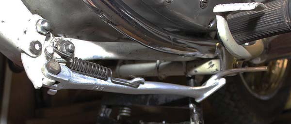
Stands - I adapted a Kawasaki ZZR600 Side Stand to fit at the frame joint below the front of the engine. A relatively easy mod and works fine. I still need to do some work on the centre stand, it works but could be better.
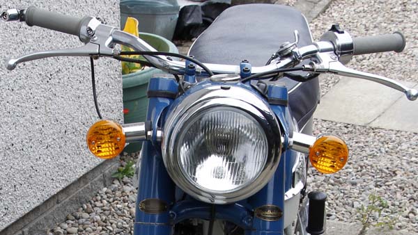
Electrics - I have rewired to 12v neg earth and fitter Boyer electronic ignition, flasher indicators, LED bulbs, a master electric switch (out of the way in the central frame section), front brake light switch (fitted under the lever), key operated ignition switch in the headlamp where the original was (I also modified the key and fitted it into the original switch knob) and the microswitch to isolate the ignition unless the oil tap is FULLY on.
I will post the main electral alteration and additions soon.
Stan
- Log in to post comments
Electrical alterations
Me Again,
Here's the changes made to the electrics.
12v Neg earth - I completely rewired the electrics, converting it to 12v neg earth. I chose neg earth mainly for LED bulbs and that most systems now use this. I know this will not go down well with a lot of the experts, but I used the colours I had available at the time and I have, and will supply, a complete wiring diagram, and there is a bagged copy in the battery compartment.
Aternator and Voltage regulator - the origenal Wipac alternator is working well and provides plenty output. I used a 4-wire single phase solid state voltage regulator which works fine.
Bulbs - most are now LEDs to reduce the load on the alternator, in consideration of its age. They all work fine and are much brighter than before.
Headlamp lens - this bike has a step down rim that uses a 5.75" lens, the one I got on ebay is a sealed beam H4 and also has a pilot light, for £16.99 I thought it was good value.
Indicators - I have fitted as set as I feel the old 'sick your hand out' system is a bit outdated these days and not safe either. They have LEDs fitted and as I can see the front lights when working I didn't have to fit a warning lamp. I shortened the rubber end on the fronts as they tended to vibrate too much, I can't see the rears when on the bike so they have been left as is. The flasher unit is a two lead unit inside the headlamp.
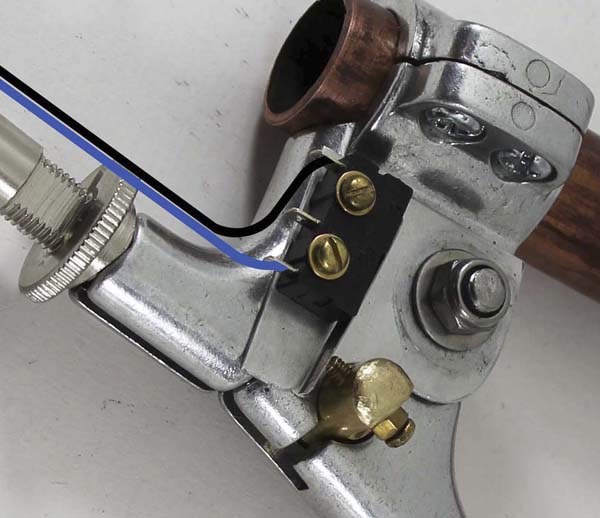
Front brake switch - again for safety, this is a microswitch fitted by two 3BA screws under the brake lever. I made a extended cable nipple with a small adjusting screw which activetes the microswitch. Being under the lever and with a thin alloy plate fitted between the lever and microswith it will be reasonably well protected from the weather. Also I don't intend using the bike in the rain unless I get caught out in it.
Master electrical switch - as these bikes can so easily be started and nicked I thought it was a good idea to fit a hidden SPDT master switch which isolates the complete system. Another advantage is that when 'OFF' the charging socket is connected directly to the battery and is isolated when 'ON' so I can't start up with the charger still on. The switch is fitted in the central frame, one advantage of no side skirts.
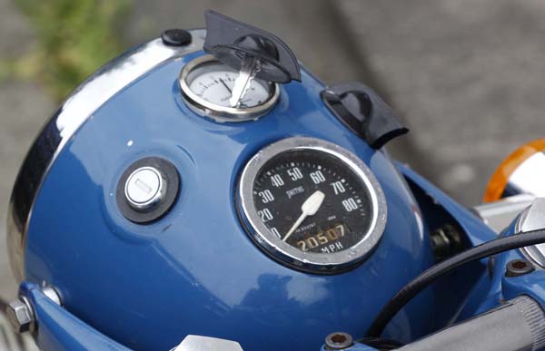
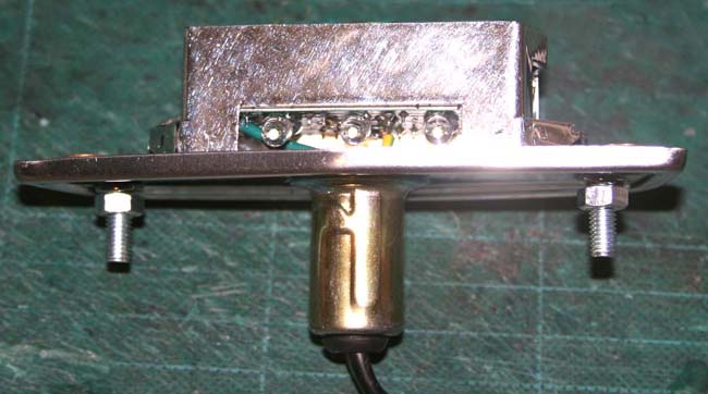
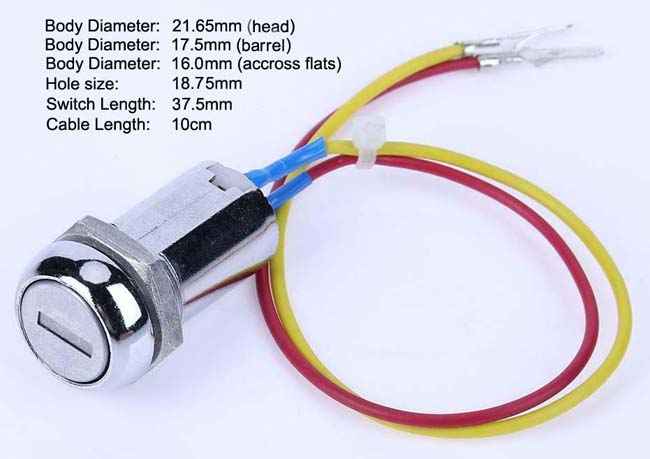
Key ignition switch - this is fitted in place of the original and only needed the hole opened out slightly. It allows me to leave the bike parked and know it can't be started even if someone finds the master switch. It also means I don't have to use the master switch when parking up for a short time. I know some will think all this is not needed, and I do agree, but as the master switch was fitted first I just left it there. I thought it was fun to add all these things and not make them obvious. The key for the switch has had the plastic top cut off and is secured inside the original switch knob so in use you don't know its there. The rubber washer is stuck to the lamp shell and helps prevent rain getting in round the switch, and the knob protects the swich internals.
Electronic Ignition - this is a Boyer Bransden Micro-MK IV unit - Part No KIT00047 for the Jubilee/Navigator and uses the original 6v coils. Ignition is set at 24deg BTDC. The unit is fitted on a small plate cable tied to the two top frame tubes behind the coils.
I think this describes most of the changes I have made, but I will update this in future if required. I hope this gives some others a few ideas for their bikes. And if you have got this far, thanks for reading.
Stan
- Log in to post comments
Clever alterations!
Hi Stan,
I like your ignition key in the headlamp. I also made a 12volt conversion to my Navigator simply by using a Lucas 12 volt stator in combination with the Wipac rotor. I made my own wiring loom and uses only the left switch on the headlamp for turning on the light. The right one is there just for decoration. My ignition switch sits under the tank front left. How did you fix the key in the switch knob? Did you glue it in? I see your bar end mirror hanging down like mine.It always turns in this position due to the vibrations
- Log in to post comments
Hi Uli, Yes I followed a…
Hi Uli,
Yes I followed a lot of your build and was thinking about the Commando seat knobs then saw you had done the same, great minds and all that. The key is secured with JB Weld, a sort of metalic epoxy I have been using since about 1980. We used to use it to repair alloy casings, great stuff.
Before I got the key switch I had fitted a master electric switch into one of the 15mm (if I remember right) holes in the central frame, so I just left it there as it is handy. Out of sight and easy enough to get a finger to it because I don't have the panels on mine. That made it handy for fitting the oil tap also.
The mirror is fine it was just where I set it when I took the bike out for photos, didn't notice the position until I had taken the pics and was checking them. I also noticed, at the same time, the damaged ammeter which has been sorted now.
Thanks for your remarks, much appreciated,
Stan
- Log in to post comments
Lucas mixed with Wipac?
Hello Ulrich. I've read many of your contributions in the past, and admired your machinery from afar.
As to mixing Lucas and Wipac, I'm sure I read on another thread or article that the lightweight Wipac alternator is dimensionally different, and the resultant increased air gap reduces the output? Were any changes or machining involved?
- Log in to post comments
Hi Ulrich, I had a loose…
Hi Ulrich, I had a loose Halcyon mirror for years till I found the concealed allen screw that adjusts the friction.
- Log in to post comments
Lucas and Wipac
Hello Michael,
my ammeter is mostly on the plus side when riding . I did not do any machining to the components
- Log in to post comments
More updates
I bought a GIDIBII rear chain oiler which has been fitted inside the frame centre section below the carb. Space is tight so I moved the electrics main switch into the battery case to clear the way for it. I also got a cheap LED rear lamp to modify my new modern copy of a Lucas Type 564 Rear Light to LEDs.
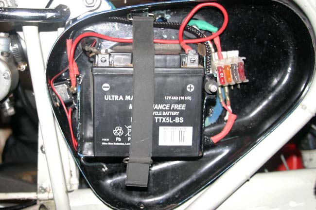
Moving the main switch - This switch has been moved to the front upper edge of the battery box just inside of the upright frame tube, and almost out of sight. Its terminals are in the space immediately in left of the battery compartment so I fitted an insulating strip of tyre rubber onto the face of the it. All the rest of the additional electrics (volt/reg, fuses, charger connection socket, the live and earth leads) are also in or on the box so it is more like a self contained electrics box now.
The battery/electrics box contains the following components:-
- Battery - this is secured by a Royal Enfield battery strap
- Fuses - 10A main fuse, 5A horn fuse, spare 10A & 5A fuses in dummy holders
- Voltage regulator - this is bolted to the back of the box. There is a recess just the right size for the unit to fit into. I drilled the holes and because the fixing bolts have countersunk heads (to reduce the intrusion into the battery compartment) I dimpled the edges so the bolt heads are flush, then a large washer was used between the battery box inner face and the unit, this allows for the dimple and also creates a space for airflow under the unit.
- Main ON/OFF switch - this SPDT 2-position switch is fitted on the side face, along with its cables (1 to battery, 2 (in an enclosure) to the fuses & 1 to charger socket). It is fairly well hidden so not easily seen but still easy enough to flick on or off as required.
- Charging adaptor - this is a 2.1mm DC socket fitted low down on the side face of the box, actually in the small compartment below the battery base. The socket points slightly down so any water getting into it will drain out.
GIDIBII Rear Chain Oiler - Because I want to keep the Navigator looking as original as possible, I looked for a mounting position so it wouldn't be too obvious. The only position I could find was in the frame centre section below the carb. This is another advantage of not having the styling panels, if I was to do it again I would go for the grey/titanium coloured version.
Fitting the GIDIBII chain oiler reservoir - To locate it in this position I removed the 5mm bolt that holds the breather pipe and alternator cable P-clips (this hole may not be standard as the breather pipe had been modified), then I filed out their holes to 6mm and ran a drill thru the frame hole. I then cut a 30mm length of 19mm stainless tube, inserted a length of 6mm ID rubber hose to make a stand-off for the oiler and secured it all with a 6mm stainless Allen headed bolt.
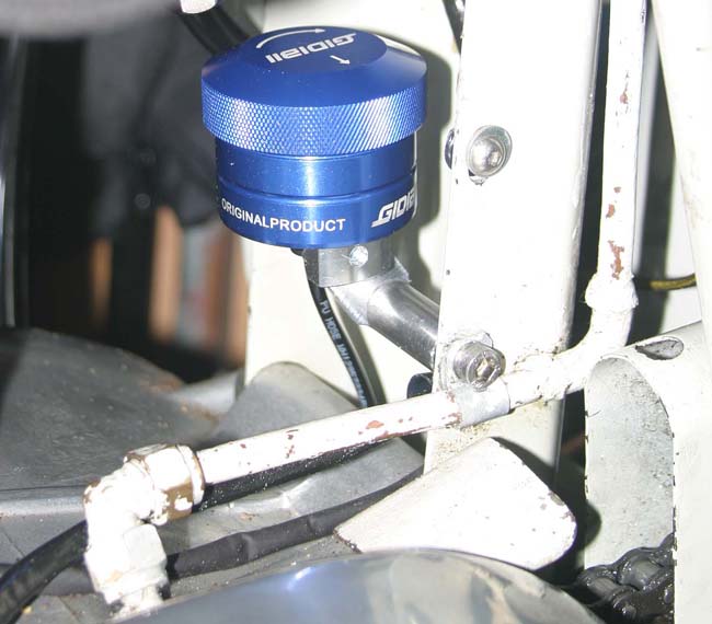
Unfortunately this is not the easiest place for it to be topped up when required, but I felt that as this won't happen all that often then I could cope with the slight inconvenience involved. I have a large syringe that makes it a little easier. I could re-route the rocker oil pipe closer up the frame to give better access to rotate the reservoir when I fill it with oil.
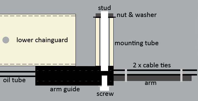
The route for the oil feed pipe - The oil feed tube runs from the reservoir down thru the space behind the gearbox and the frame, then out between the top and lower chain runs, back under the swing arm pivot, along the joint between the LH swing arm leg and the lower chainguard to the adjustable arm guide mounted at the end of the chainguard then down to the chain just in front of the sprocket. The feed tube is secured to the chainguard by the two supplied clamps, thru the guide block and along the extension arm.
Chain oiler arm guide mod - To fit this I used the mount tube that is fitted under the swing arm for the lower part of a full chainguard. This has an internal dia of 1/4" and is approx 1 3/16" long. To use this I tapped a 5mm thread in the inner arm guide hole that is the alternative position for the screw that holds the arm on the other side. I made a 50mm long stud by cutting the head off a long 5mm bolt. This was then screwed into the arm guide and locked with Loctite bearing fit. I then fitted thin double sided adhesive tape to the top and inner face of the arm guide and attached this to the swing arm and lower chainguard then secured it with a washer and nut at the inner end of the stud. The arm was fitted and the oil tube fitted thru the guide and held along the arm, by two cable ties, not thru the long lower slot as designed due to the alignment of this setup. The oil tube was bent to align the oil drips onto the centre of the chain run. To give it stiffness to retain the bend I have used a length of brass tube pushed up inside the plastic tube.
Once filled and primed the system works fine. It is a bit awkward to use due to the location I selected but that's life when working on old bikes and wanting to keep the looks as original as possible.
Converting My Lucas Type 564 Rear Light to LEDs
Because the rear lamp on my Navigator was in poor condition and repairs were not, in my opinion, satisfactory I decided to buy a new replacement. This was a modern copy and although it worked ok I decided to see if I could convert it to using LEDs.
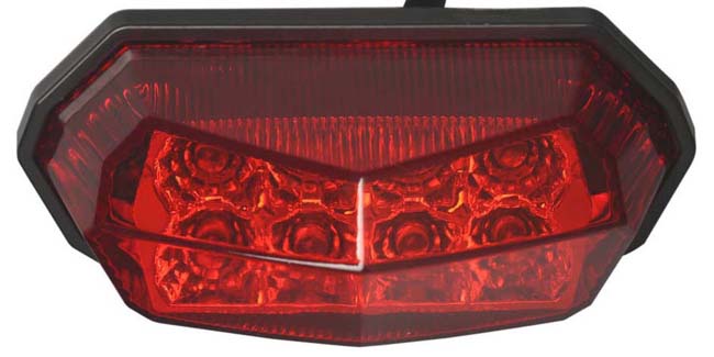
To do this I bought a lamp like the one shown above. This was dismantled, rather the lense of the lamp was cut away from the base, then the LED board and reflector unit removed. The bulb holder and leads were removed from the Lucas lamp and then the LED unit was trimmed where it contacted the internal screw heads in the Lucas lamp and secured to the inside of the lamp base. The leads come out thru the hole for the original lamp holder leads.
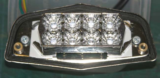
At the moment for trials the led unit is just secured with double sided tape, I will probably use silicone later once I am happy with it. The silicone will give it added protection from vibrations and seal the leads entry.
So now I have a new looking rear lamp with better LED lighting which should survive the vibrations of a parallel twin and with no filamenmt bulb inside to blow and need replacing.
Cheers,
Stan
- Log in to post comments
LED rear light
Hello Stanley,
with all those improvements you should speak up to TVS Norton, maybe they also resurrect the Lightweight range...
There is a LED bulb available for the rear light which fits into the socket, also with positive earth.
I have on one my Navi.
Which ignition lock did you sue? A generic one?
- Log in to post comments
Thanks for the update…
Thanks for the update Stanley, dare I ask why the breather pipe from the chain case to oil tank? And why not in rubber?! I think mine just has a small pin hole.
it wont be long before we use up the supply of Kawasaki side stands!
Dan
- Log in to post comments
Ulrich & Dan
Thanks both for your replies,
Uli, I got the switch on ebay, I see there is one on just now, item number 403744518357. You will see why I wanted to change the key fob!!! I did the LEDs that way just to see whet it looked like and it was another way of doing it, permanent I hope.
Dan, ask away, that's how we find things out. That is how the breather pipe was when I got the bike. Don't know what has been done at the engine end as I haven't had the inner primary off.
The Kawasaki stand was an easy fit and works well.
Cheers,
Stan
- Log in to post comments
I think I have used 3…
I think I have used 3 Kawasaki stands, one on my jubilee, one for a navigator project and one on my short stroke ES2!
There shouldn’t be any pressure in the chain case unless the crank seals have gone, I had to change mine as it was spewing oil out!
Dan
- Log in to post comments
breather pipe
The metal breather pipe is a replacement for the normal rubber one, probably the original one got zapped by the rear chain at some time.
So it's you that's using all the side stands, you'll be pushing the price up.
Stan
- Log in to post comments


Bike looks stunning and the right rear indicator is brand new, still in its plastic bag!