
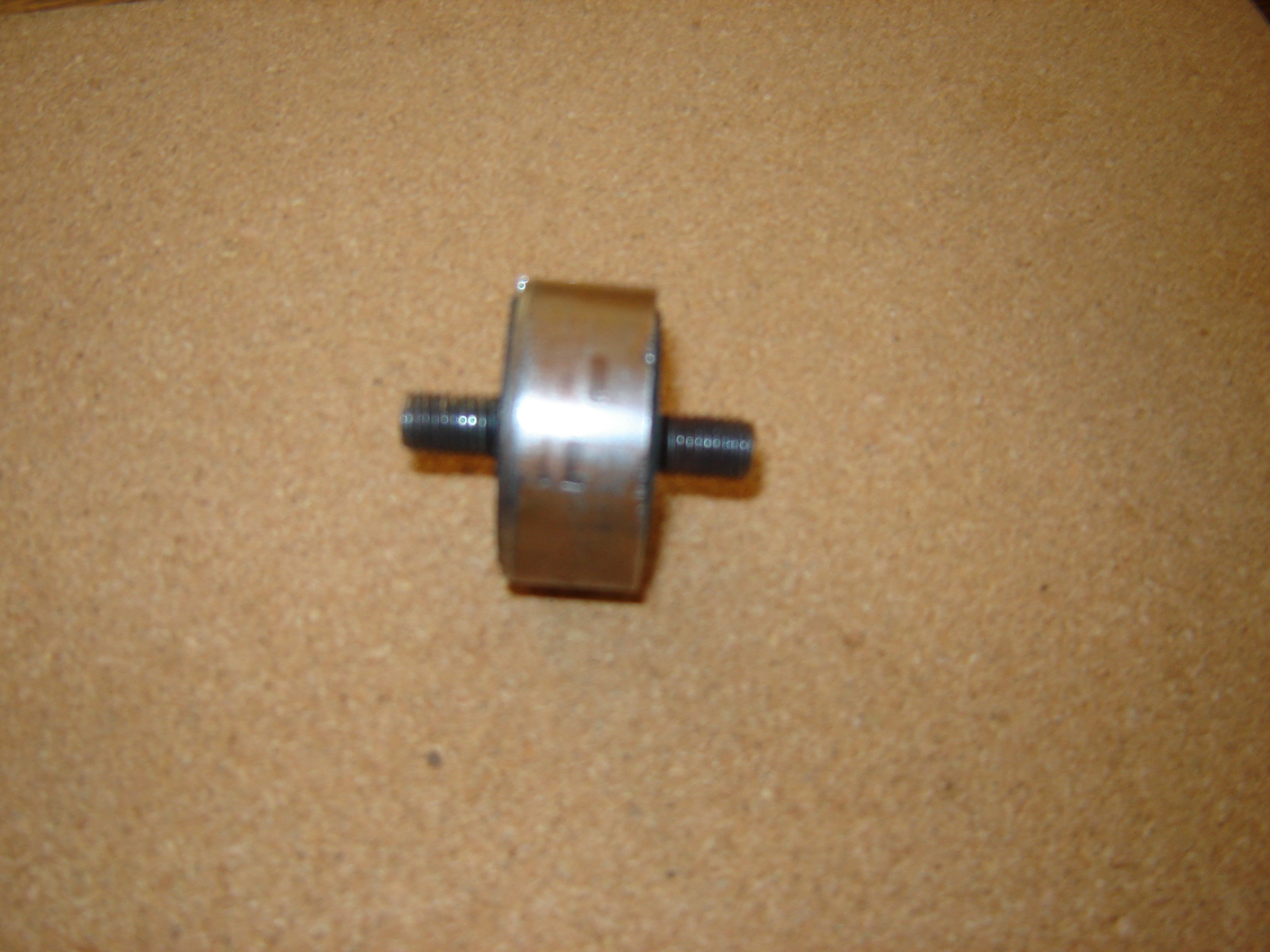
As my Commando is in bits ready to cobble back together I have had time to consider a few things I have found a bit strange to do with the top head steady. IMO it is at best shabby. Clearly the nuts holding the triangle to the frame rubbers have moved about. I have decided to make a triangle thing out of 6 mm alie and drill the holes one side at a time to ensure they line up. That way the whole gestalt cant move as there is no slot to move in. Thus the vibes will be force to deal with the rubbers. As the rubbers lay on the bench I had a thought, it does happen sometimes. I had an old piece of Velocette fork bushing on the window sill. It looked close in I/D size to the Norton rubbers. I slid the bush over the rubber and found that the 'sleve effect' allowed the rubber to move easily in torsion but not much in other directions. I cut the bushing down to 1 mm less than the width of the rubber and smothed the ends. Fitted to the frame the rubber was considerably stiffer in resistance in all but torsion. I tested it with no sleve and the difference is huge. With both rubbers sleeved, by the old Velo bush, the head steady is far more rigid than without the sleeve. After all, the ISO system has the rubbers inside a tube. The sleeve thing must be a bit narrower than the rubber to let the rubber move by not having the metal end discs captive. I think it would work better if a cup with a center hole went over the rubbers from the frame side.
As I wont have the bike running for a while does anyone in Norton land feel like trying it out and getting back with the results ?
The idea is that by simple getting some tube, and cutting it to fit, the bike will be a better ride. Cheap and easy to do. I don't want to pay for one of those after market head steady gizmos.
What do you lot think ?
Attachments
DSC02169.JPG
Well, David, here are my v…
- Log in to post comments
I think your idea has meri…
I think your idea has merit, a similar version uses 2 nylon pucks in place of the rubber buffers, they are sized so there is a few thou clearance from the side plates so limiting the movement to up and down only as the nylon is more solid than the rubber. A more involved version developed by Dave Taylor uses rod links, again to limit movement to up and down only.
- Log in to post comments
The Dave Taylor head stead…
The Dave Taylor head steady is the best I've found transformed the ride ððð
- Log in to post comments
I have a Dave Taylor head…
I have a Dave Taylor head steady which I found worked well. They are £105 now so not cheap. But if you price up all the parts for a MK 3 head steady then it is not that much more.
- Log in to post comments
Mike Taglieri made his own…
Mike Taglieri made his own head steady from bits of angle and a pair of rose joints. This is the basis for the Dave Taylor item. I'm not sure whose was the first, but I made one and it works as advertised. It allows for and aft movement and vertical movement but no sideways. I keep meaning to add the support spring to mine as per the Mk 3 but despite the bits sitting in my garage I have not got round to it. Rose joints are available from bearing suppliers, mine came from the scrap bin off the tail rotor of a Bell 412 (doesn't go any faster)
Attachments
images-jpeg
- Log in to post comments
Previously david_evans wro…
Previously david_evans wrote:
Mike Taglieri made his own head steady from bits of angle and a pair of rose joints. This is the basis for the Dave Taylor item. I'm not sure whose was the first, but I made one and it works as advertised. It allows for and aft movement and vertical movement but no sideways. I keep meaning to add the support spring to mine as per the Mk 3 but despite the bits sitting in my garage I have not got round to it. Rose joints are available from bearing suppliers, mine came from the scrap bin off the tail rotor of a Bell 412 (doesn't go any faster)
Ha Ha, that was my pic and crudely dimensioned aluminum version of Mike T's angle iron job. It did work but I'm back to the stock 850 with Mk3 spring to try and tune out the lower rpm vibes. That has done nothing for the vibes despite various spring tension settings though. One of the other reasons I removed it was the lack of vertical support for the main ISO's but that's flawed really as a pair of exhaust bobbins cannot be doing a lot....
- Log in to post comments
Thanx for all the replies.…
Thanx for all the replies.
I know about the Taylor head steady thin, it's good but costs money.
I was thinking about making one of those Taylor gizmo's, then mass producing them for 1/4 the price they go for.
But my thoughts were about saving a buck.
The idea I had was to simply restrict the axsis of rotation in all but the Z plane.
The rubber in my idea allows the motor to move up and down but in a twisting motion it is quite restricted.
I was wondering if it would stop the movement the Taylor unit prevents but much cheaper.
As I'm going to have a spinal fusion op ( 6 ) to fuse my spine I'm not going to be able to do much to the bike for a while.
I'll try to post a foto on here of my gizmo soon.
Chocks away.
D
- Log in to post comments
According to my records I…
According to my records I fitted the original link to my 76 Mk3 850 on the 3/4/02 and it is still in service today. Other than a wipe and a drop of lube whenever the tank is off it has been a fit and forget item. One unexpected benefit has been the the lack of required maintenance to the ISOs
I had the idea to fit a link some four or five years earlier but could not really afford to gamble £25 on a pair of rose joints. (Times were hard then).
It is indeed quite easy to cobble up a link steady and the satisfaction of making your own is priceless. However if you have a pre Mk3 I would recommend you buy the Mk3 spring, trunnion adjuster, and mount. This will enable you to tune out the 2000 to 3000 rpm vibes.
Dave.
- Log in to post comments
Previously allan_walker wr…
Previously allan_walker wrote:
Well, David, here are my views.
If the Velo bushings are metal, I think that you will only succeed in preventing the head steady components working as they should.
Perhaps if you could post some pictures it may clarify things.
The engine should be able to vibrate in a vertical and front-to-back plane. This is achieved (as far as the head steady is concerned) by the rubber mountings flexing. A metal tube over the top of the rubber mounts is likely to prevent this flexing.
The only intended effect of the head steady, as far as confining movement of the engine is concerned, is in the side-to-side plane.
The slotted holes in the triangular plates are to allow for tolerances (manufacturing and also settlement in the isolastics.) Before tightening the nuts either side of the slotted holes, the bike should be on its wheels (i.e. not on the centre stand) so the head steady rubber bushes find a neutral, unstressed position. Then tighten the nuts. If they are tight, they should not work loose in service.
(Health Warning: Other opinions may vary......
)
Good luck with recommissioning your bike. I've recently got my Mk3 back on the road after a long lay-up.
(I'm assuming that you are referring to a standard head steady setup, rather than an aftermarket one.)
Thanx Allan. I have posted a pic of the tube over rubber head ISO. The motor can move up and down but cant 'twist'
much at all.
- Log in to post comments
Thanks for the picture, Da…
Thanks for the picture, David.
Looking at it, and re-reading your original post, I think I'll stick with my original assessment (which is purely my opinion  .)
.)
Those rubber buffers in the head steady are meant to operate by flexing. Imagine a line drawn through the two mounting studs. The movement allowed by the head steady means that the two mounting studs constantly move out of alignment with each other, although remaining parallel.
(Of course, the rubber will also tend to compress and stretch along the axis of the studs, leading to side-to-side movement. The Dave Taylor rose-joint link is designed to stop this side-to-side movement.)
Placing a metal sleeve over the rubber, even if not in contact with the metal discs, will constrain the possible movement of the rubber which in turn will limit the relative movement of the mounting studs (i.e. they will not be able to move out of line with each other to the original, intended degree and so the engine movement will be restricted in the vertical and horizontal planes.)
When you refer to the fitting of the sleeve allowing 'the rubber to move easily in torsion,' I'm not sure if I understand you correctly. There will be marginal torsional movement (a twist along the axis of the mounting studs) of the standard head steady set-up compared with the amount of fore-and-aft and up-and-down movement.
I think that sleeving the rubbers as you describe will limit engine movement (in the designed directions) in a similar way that isolastic rubbers which are too hard would do. Nett result, more vibration.
As our transatlantic friends are wont to say 'your mileage may vary.' 
Of course, the proof of the pudding is in the eating! Your suggested modification looks dead easy to do (and just as easy to undo, if necessary,) so why not give it a try in practice. Then please feel free to shoot me down in flames......
How are you getting on with the rebuild generally?
- Log in to post comments
Previously allan_walker wr…
Previously allan_walker wrote:
Thanks for the picture, David.
Looking at it, and re-reading your original post, I think I'll stick with my original assessment (which is purely my opinion
.)
Those rubber buffers in the head steady are meant to operate by flexing. Imagine a line drawn through the two mounting studs. The movement allowed by the head steady means that the two mounting studs constantly move out of alignment with each other, although remaining parallel.
(Of course, the rubber will also tend to compress and stretch along the axis of the studs, leading to side-to-side movement. The Dave Taylor rose-joint link is designed to stop this side-to-side movement.)
Placing a metal sleeve over the rubber, even if not in contact with the metal discs, will constrain the possible movement of the rubber which in turn will limit the relative movement of the mounting studs (i.e. they will not be able to move out of line with each other to the original, intended degree and so the engine movement will be restricted in the vertical and horizontal planes.)
When you refer to the fitting of the sleeve allowing 'the rubber to move easily in torsion,' I'm not sure if I understand you correctly. There will be marginal torsional movement (a twist along the axis of the mounting studs) of the standard head steady set-up compared with the amount of fore-and-aft and up-and-down movement.
I think that sleeving the rubbers as you describe will limit engine movement (in the designed directions) in a similar way that isolastic rubbers which are too hard would do. Nett result, more vibration.
As our transatlantic friends are wont to say 'your mileage may vary.'
Of course, the proof of the pudding is in the eating! Your suggested modification looks dead easy to do (and just as easy to undo, if necessary,) so why not give it a try in practice. Then please feel free to shoot me down in flames......
How are you getting on with the rebuild generally?
Thanx Allan,
When all assembled, with added metal sleeve, and fitted on the bike the factory head steady will move freely up and down, almost as much as stock. But when twisting in any other direction there is a lot of resistance but not hard locked.
I'm going to have spinal fusion surgery in a week or two so not much will be done for a few months as I have to go through rehab etc. But I will get it all back into one lump by years end, God willing.
I'll try this idea out then. Problem is, I'm a bit of an OCD type when restoring bikes so it takes me a bit more time than most people. I have to have it all perfect. I clean every nut, washer and bolt, and everything else back to like new. I can't stand shabby work, what's the point?
Thanx for your kind input.
Dave
Attachments
DSC02127.JPG
DSC02142.JPG
technical4-
- Log in to post comments
Previously dave_taylor wro…
Previously dave_taylor wrote:
According to my records I fitted the original link to my 76 Mk3 850 on the 3/4/02 and it is still in service today. Other than a wipe and a drop of lube whenever the tank is off it has been a fit and forget item. One unexpected benefit has been the the lack of required maintenance to the ISOs
I had the idea to fit a link some four or five years earlier but could not really afford to gamble £25 on a pair of rose joints. (Times were hard then).
It is indeed quite easy to cobble up a link steady and the satisfaction of making your own is priceless. However if you have a pre Mk3 I would recommend you buy the Mk3 spring, trunnion adjuster, and mount. This will enable you to tune out the 2000 to 3000 rpm vibes.
Dave.
Thanx Dave.
- Log in to post comments
It's interesting to read…
It's interesting to read that the rubber bushes allow movement even when you have fitted the sleeves. You could be on to something here.
I agree that it's best to do a job properly, once, rather than a 'quick fix,' although this does have a 'stretching' effect on schedules!
Good luck with your operation, Dave. I look forward to your report when the bike is re-assembled!
- Log in to post comments
Previously allan_walker wr…
Previously allan_walker wrote:
It's interesting to read that the rubber bushes allow movement even when you have fitted the sleeves. You could be on to something here.
I agree that it's best to do a job properly, once, rather than a 'quick fix,' although this does have a 'stretching' effect on schedules!
Good luck with your operation, Dave. I look forward to your report when the bike is re-assembled!
Thanx mate.
- Log in to post comments
Previously allan_walker wr…
Previously allan_walker wrote:
It's interesting to read that the rubber bushes allow movement even when you have fitted the sleeves. You could be on to something here.
I agree that it's best to do a job properly, once, rather than a 'quick fix,' although this does have a 'stretching' effect on schedules!
Good luck with your operation, Dave. I look forward to your report when the bike is re-assembled!
Hi Allan.
Back on deck after the fusion operation. Slowly working on the 850. I'm going to do the head steady as planned to see if it will work in the real rideing situation. It will take time to get it on the road, some day it will happen. Sooner that later I hope.
Pip pip, Dave
- Log in to post comments
Happy New Year, Dave. Good…
Happy New Year, Dave.
Good to hear that the operation was successful. Take it easy with bending and lifting!
Cheers,
Allan.
- Log in to post comments
Previously allan_walker wr…
Previously allan_walker wrote:
Happy New Year, Dave.
Good to hear that the operation was successful. Take it easy with bending and lifting!
Cheers,
Allan.
Thanx Allen. Slowly getting fit by swimming in the sea and long walks with my dear wife. Just making up a long list for needed parts. Don't know where the best deals come from. Looking for top quality items.
D
- Log in to post comments


Well, David, here are my views.
If the Velo bushings are metal, I think that you will only succeed in preventing the head steady components working as they should.
Perhaps if you could post some pictures it may clarify things.
The engine should be able to vibrate in a vertical and front-to-back plane. This is achieved (as far as the head steady is concerned) by the rubber mountings flexing. A metal tube over the top of the rubber mounts is likely to prevent this flexing.
The only intended effect of the head steady, as far as confining movement of the engine is concerned, is in the side-to-side plane.
The slotted holes in the triangular plates are to allow for tolerances (manufacturing and also settlement in the isolastics.) Before tightening the nuts either side of the slotted holes, the bike should be on its wheels (i.e. not on the centre stand) so the head steady rubber bushes find a neutral, unstressed position. Then tighten the nuts. If they are tight, they should not work loose in service.
(Health Warning: Other opinions may vary...... )
)
Good luck with recommissioning your bike. I've recently got my Mk3 back on the road after a long lay-up.
(I'm assuming that you are referring to a standard head steady setup, rather than an aftermarket one.)