
My name, Lester Powell, Barnsley.
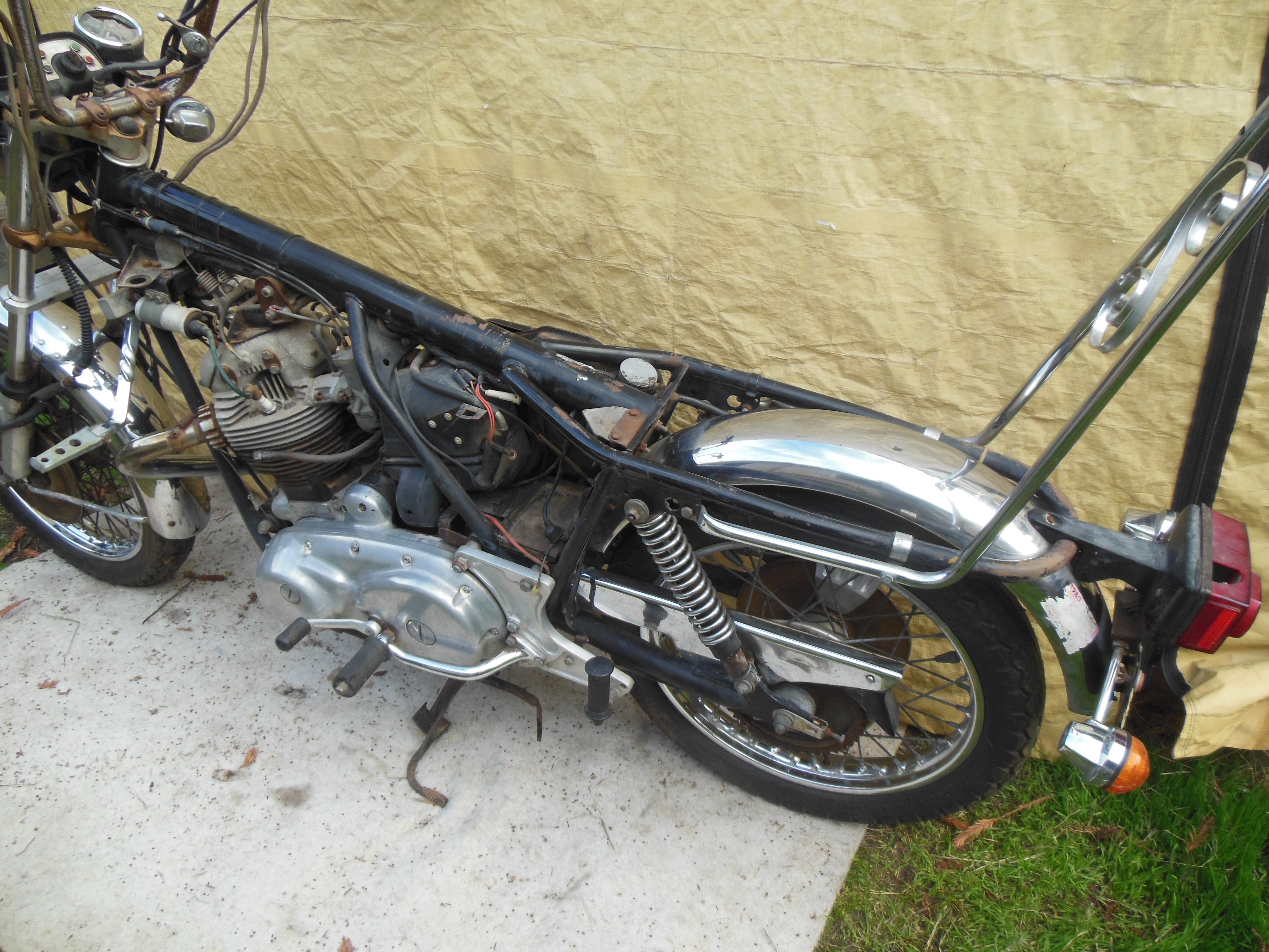
Approx 3 years ago I purchased a long time dream Norton Commando MK3
This 60% built motorcycle has had the engine completley refurbished at Norvil.
Over the past 3 years I having carried out some building on the bike I did not have the time to finish the build, however in the current climate with the Virus causing havoc we have a lot of spare time on our hands. I am at the point with the wiring where from the front (headlight & handle bar switches) to the battery all is OK, but from here on in, I have no knowledge where all the connections attach to :- frame, components , starter, battery etc.
The previous owner stripped the whole bike and did not mark all the existing connections and parts locations.
So I will be asking for more assistance as I proceed.
I have a good and varied mechanical knowledge as I served an apprenticeship as a mechanical engineer and have had motor cycles from an early age ( 12 years old) and to date never been without a bike of some type since. I also own a 1974 Triumph Daytona 500 which is my two wheeled transport at the moment but the Commando is the dream.
I hope some of you can offer pics of your bike's set up especially the wiring connections.
Regards to all
Lest
Wiring for MK 3 Commando
- Log in to post comments
Hi Lester
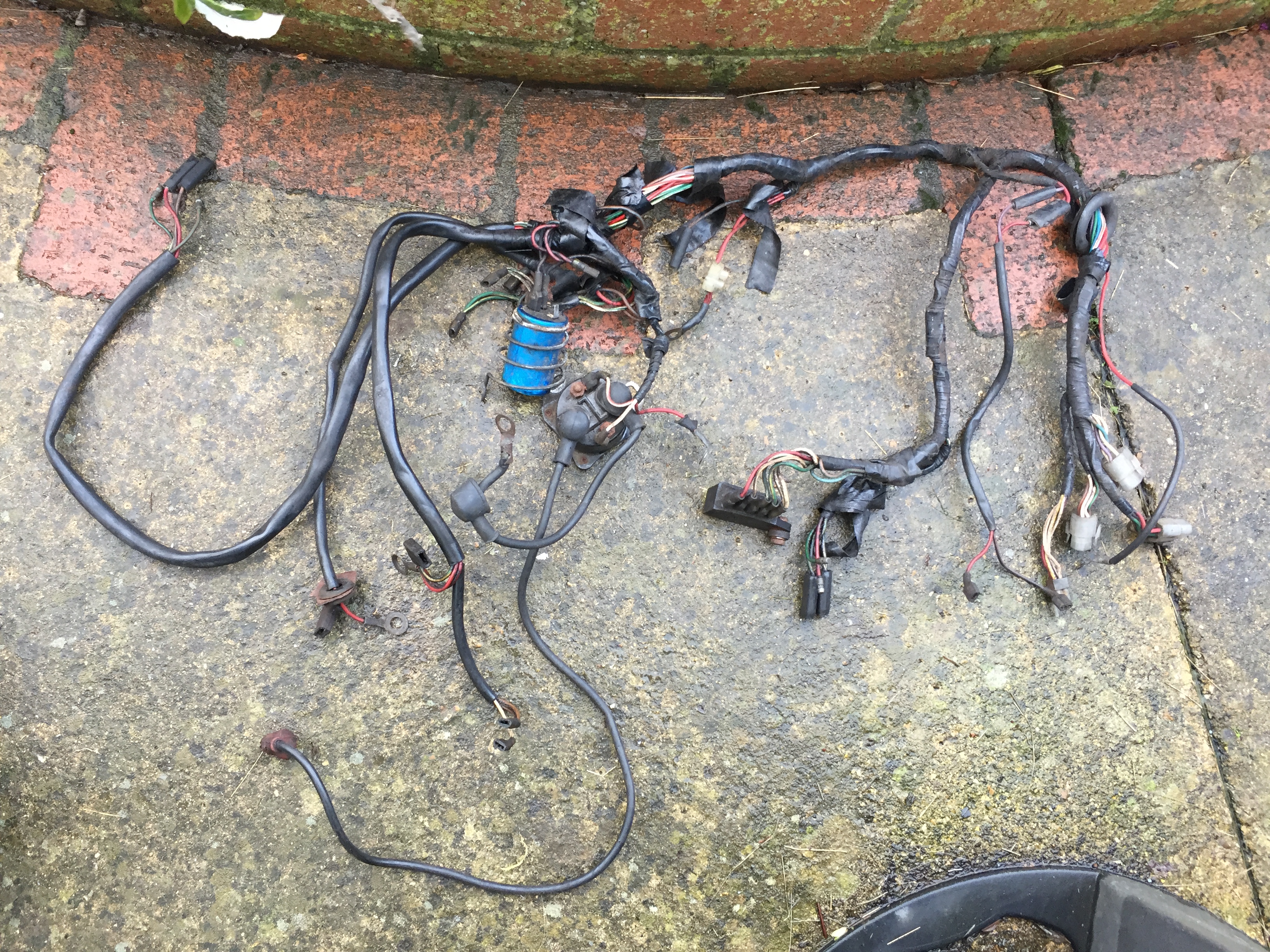
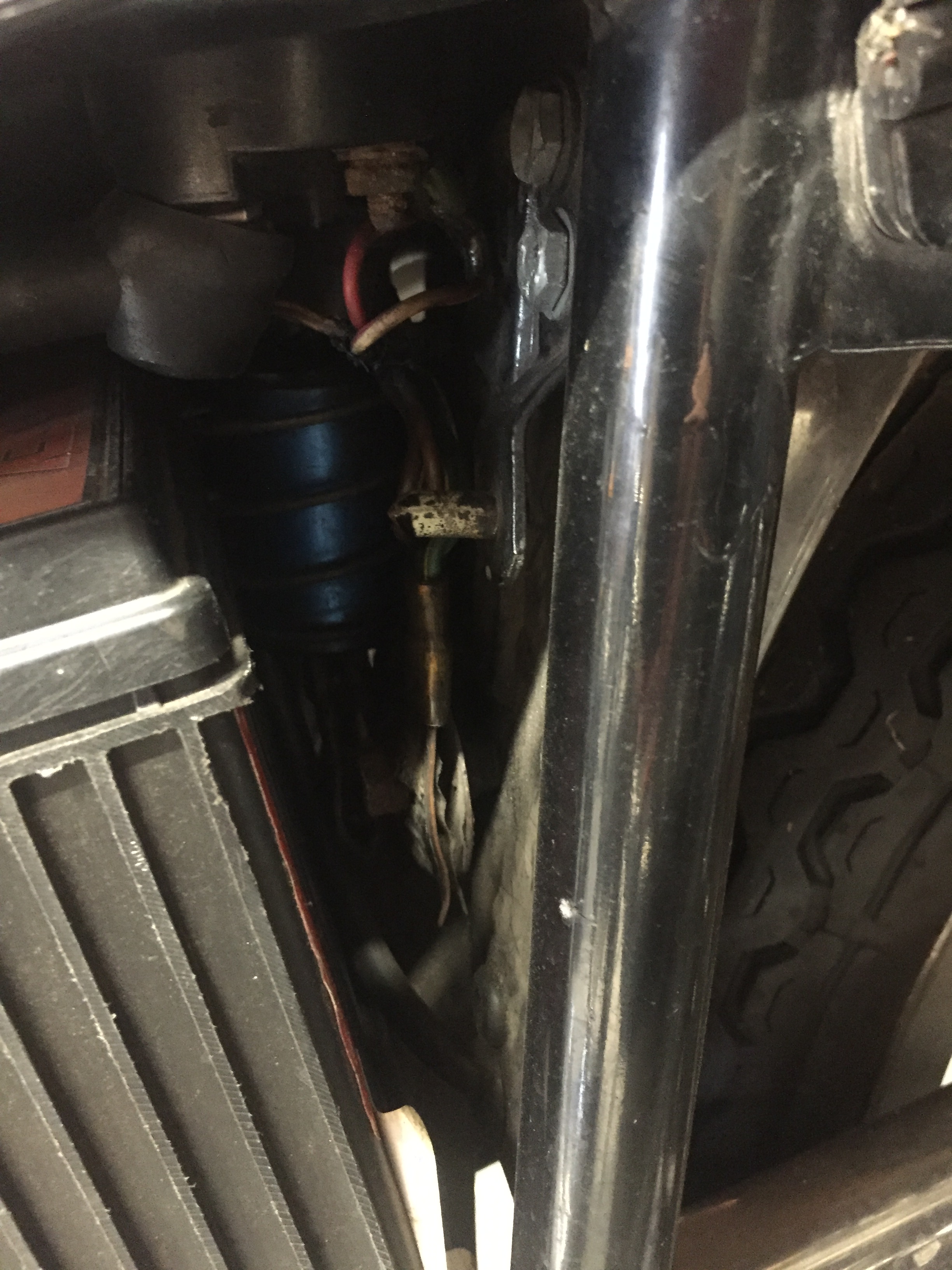
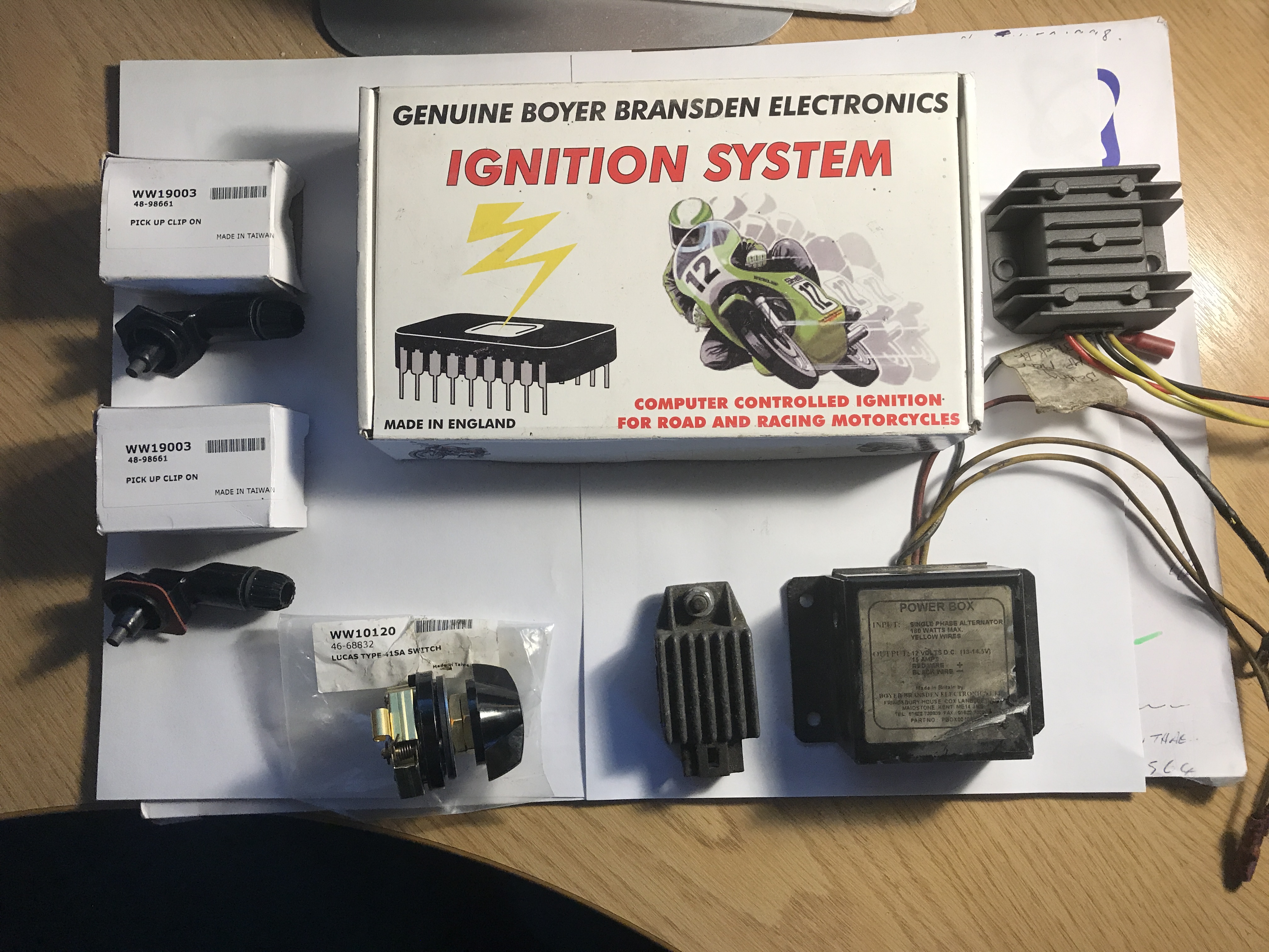
Do you have a wiring diagram for the bike? This will make things much clearer. With regard to your photos, I'm not sure what you're showing in pics 1&2 (although 1 has one of those horrible scotchlok things). The third picture shows an assortment of items - the black box with no fins looks like a Boyer Bransden ignition box which may suit your bike, the finned thing below it looks like a regulator (but possibly not for your bike), the smaller finned box could be anything; the 2 items at the top are magneto pickups which have nothing to do with your bike and the switch again looks as if it's from something else entirely.
There's a nice diagram here
Note that the Commando is positive earth so all the red wires are earths.
- Log in to post comments
reply to Ian
Hi, Thanks for your e mail.
Yes I have a wiring diagram from the manuak I purchased fro Andover-Norton which I have now expanded to A1 to hopefully make it clearer.
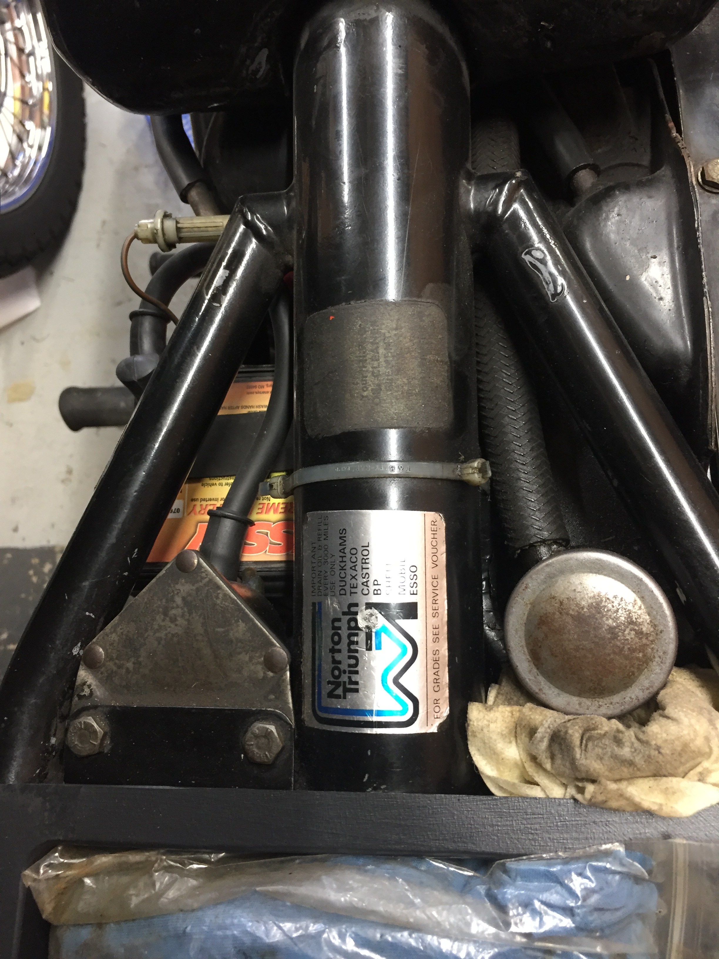
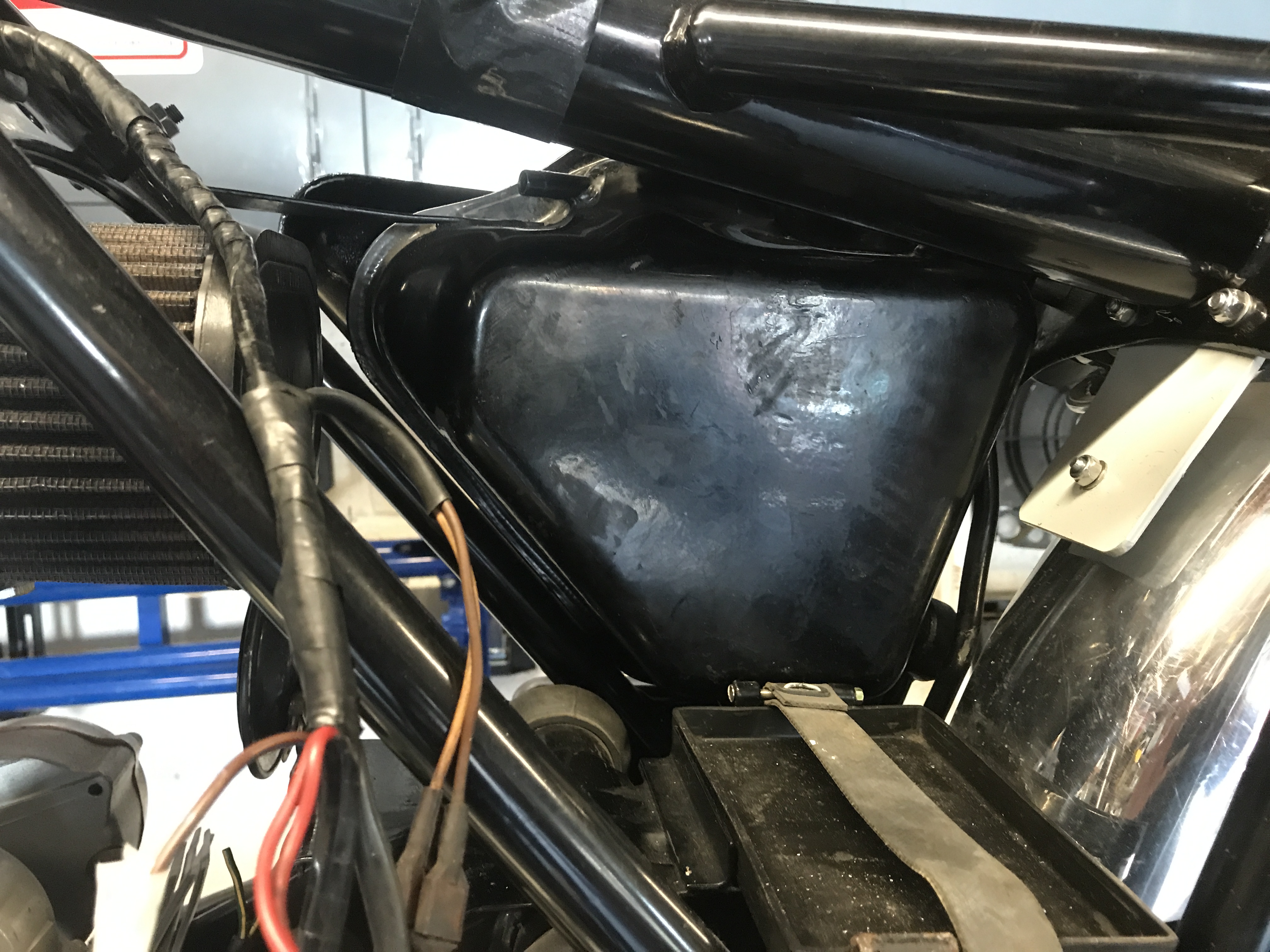
The first two pics show an area ( battery location box) where someone said components were situated in this space and yes the scotch connector will be discarded.
I have an assortemnt of colour coded connectors , bullet, spades etc to use as I make progress.
As I said my forte is mechanical ,but if I had stripped the original all would have had tags and photos. As it is I have no clue where any components are located & fitted to then frame and where the wiring is routed.
I could do with some pics of a standard MK3 showing the cable runs and connections.
Lest
- Log in to post comments
I don't think pictures of…
I don't think pictures of someone else's wiring is going to help you much. Might help with cable routing but otherwise you'll just see a bunch of coloured wires wrapped in black sleeving disappear into a connector block. Follow the wiring diagram and colour codes and you'll be fine. There's one in the Haynes manual.
Don't think it's fair to criticise the PO; if he pulled the loom off without unwrapping it then you can just lay it back in place and match up the colours. If it's a mix of original, new and DIY then you won't want to put it back as it was anyway. You might have trouble mating old and new 'cos they originally used multi-way connectors but the looms available now use bullets. I recommend modern DEUTSCH multi-way connectors if you decide to replace connectors. Whatever you do, get rid of those nasty blue snap connectors visible in the first picture.
These people can supply cable in most of the colourways used on Commandos https://kojaycat.co.uk/ . Unfortunately they're closed for the duration.
I re-wired my Mk3 from scratch as what I'd inherited from the PO was in a rather sorry state. Not that difficult, honest. Definitely worth taking the opportunity add relays into the headlamp circuit to help 45 year-old switchgear and replacing the rectifier and zeners with a modern all-in-one box (which you might have in pic #3).
- Log in to post comments
Hi LestI am sure than many…
Hi Lest
I am sure that many of us looked at your first request and wanted to help, but there really isn't much we can do or say. I have rewired my Mk3 twice now since new. Yours seems to have been rewired from the photos so you have no option but to study and understand motorcycle wiring or hand it over to someone who does it for a job (try Al Oz in the membership magazine).
If you want to have a go then read a basic book on motorcycle electrics, look at the MK3 wiring diagram and redraw it for yourself, then take apart the current loom that you have and draw out what you think it may be doing. There are several changes that can and should be made to the original Mk3 loom and it is at that point that we can pitch in with help on what we might have done.
Norm
- Log in to post comments
MKIII wiring
I see in the pix you have one of the starters I build....
Good if you have the wiring schematic. However just in case you have vin/SN 325000 through approximately 327000 you have an unpublished early bike wiring. The main difference is in the fuses and headlight bucket area.and WLA.. Post it here if this is your situation....and is a problem.
- Log in to post comments
The Boyer Power Box is the…
The Boyer Power Box is the non standard rectifier and voltage controller to turn the AC from the alternator to DC to keep the battery charged. It also has a big capacitor inside so you can start and run with no battery if you wish, and not blow the lights.
But alongside it are some other regulators. You have to ask why? Maybe the Boyer box stopped working...those regulators should do much the same job but don't have the capacitor.
Wiring for the Boyer should be on their web site. Likewise for the other regulators.
Have fun!
- Log in to post comments
45 year old wiring
My advice would be to replace all the wiring after having all electrical components checked out or replaced, having first assessed what you have and what is advailable.
If you plan to use the electric start you need to upgrade some parts and the Zenners are not available, what state is you alternator in?
As it is off the road now is the time to try to make it reliable.
I would talk to Al Oz as a first step and get a book and a DVM.
- Log in to post comments
Hi Lest, I have tried to…
Hi Lest,
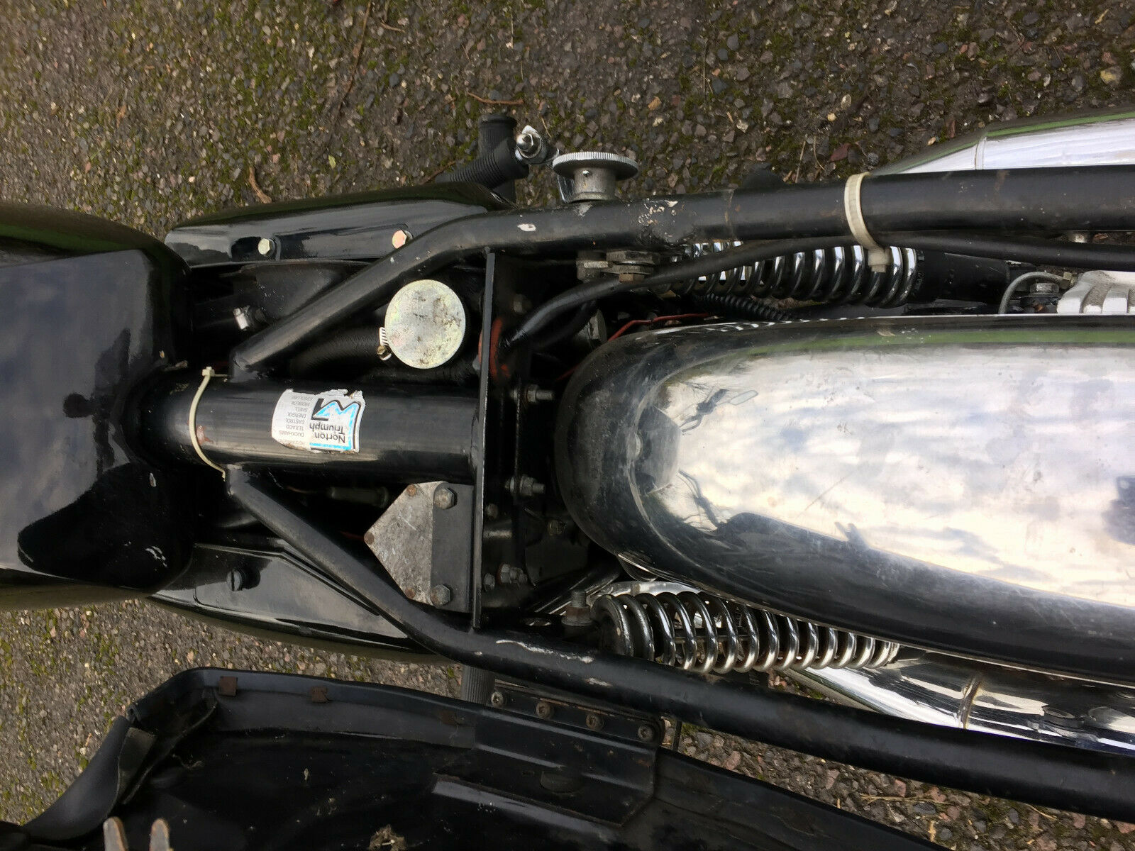
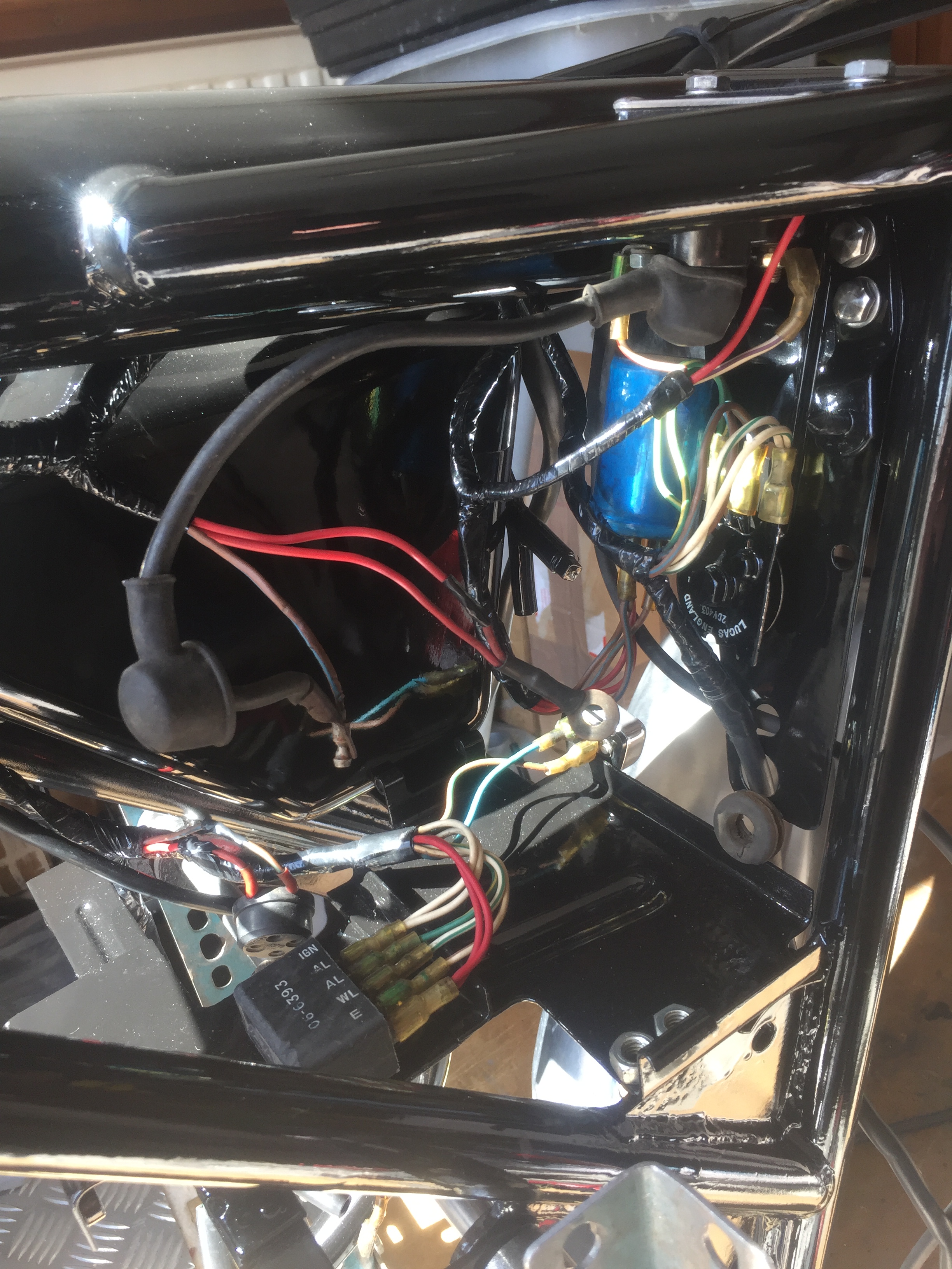
I have tried to attach a picture of a Mk3 main loom with some of the components still connected.
v
Best wishes, Al.
- Log in to post comments
reply to Al
Hi, Al, thanks for the pics, really helpful,
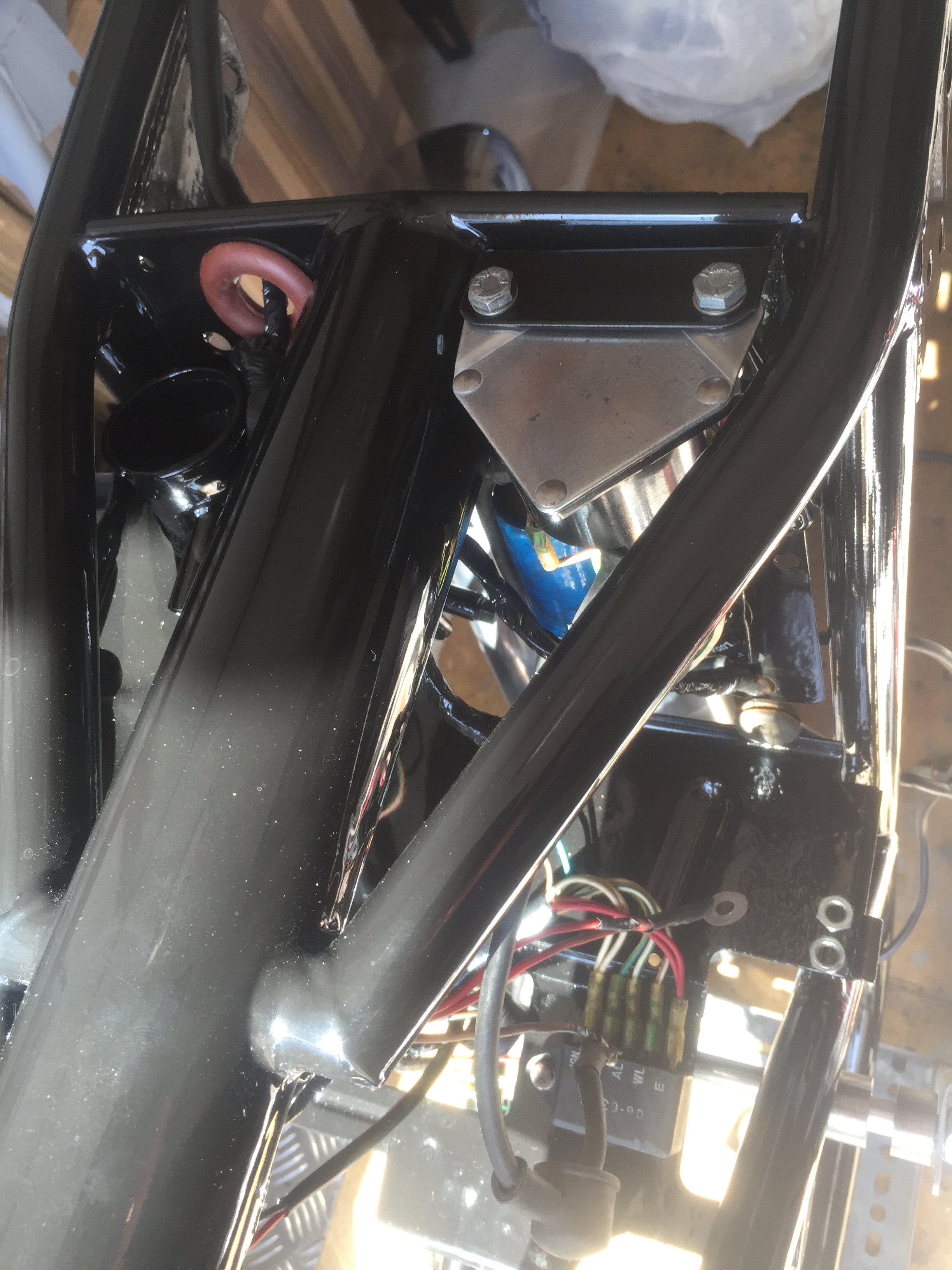
Your pics have also answered another couple of issues ,nothing to do with the wiring but where a spacer is required on the frame and the plate adjacent the oil tank.
This leads me to think I really need to see a standard MK3 for so many reasons.
Diagrams and exploded views are all well and good but looking at the real thing would help me better than any literature.
I have a manual purchased from Andover Norton but I may invest in a Haynes Manual , may be more explicit.
KR
Lest
- Log in to post comments
I wouldn't bother....
.. the official manual is far better and more accurate. It's also worth getting a copy of the Norton Commando Service Notes which I believe may still be available from the Club. Failing that it was recently serialised in Roadholder.
- Log in to post comments
If you want photo's look for…
If you want photo's look for an original Clymer Commando manual on ebay, the photo's are clearer (I guess they had a bigger budget & used new bikes!)
Note that the composite Clymer manual (covering BSA/Triumph &/Norton) does not have the same coverage as the specific version (but may suffice for your needs).
Mike
- Log in to post comments
Hi Lest, I do have quite a…
Hi Lest,
I do have quite a few reference photos so will help if I can.
This may also be of some help.

Regards, Al.
- Log in to post comments
FURTHER...
Very interesting...The items in the pictures right in the beginning are as said. Two off Mag pickups-Not Needed, one off Dynamo type lighting switch NN. One of small finned regulator for dynamo NN. Two type alternator regulators, the dirty old one is a Boyer Bransden with cap inside (known to fail) the newer one is an A reg type as sold by me and others.
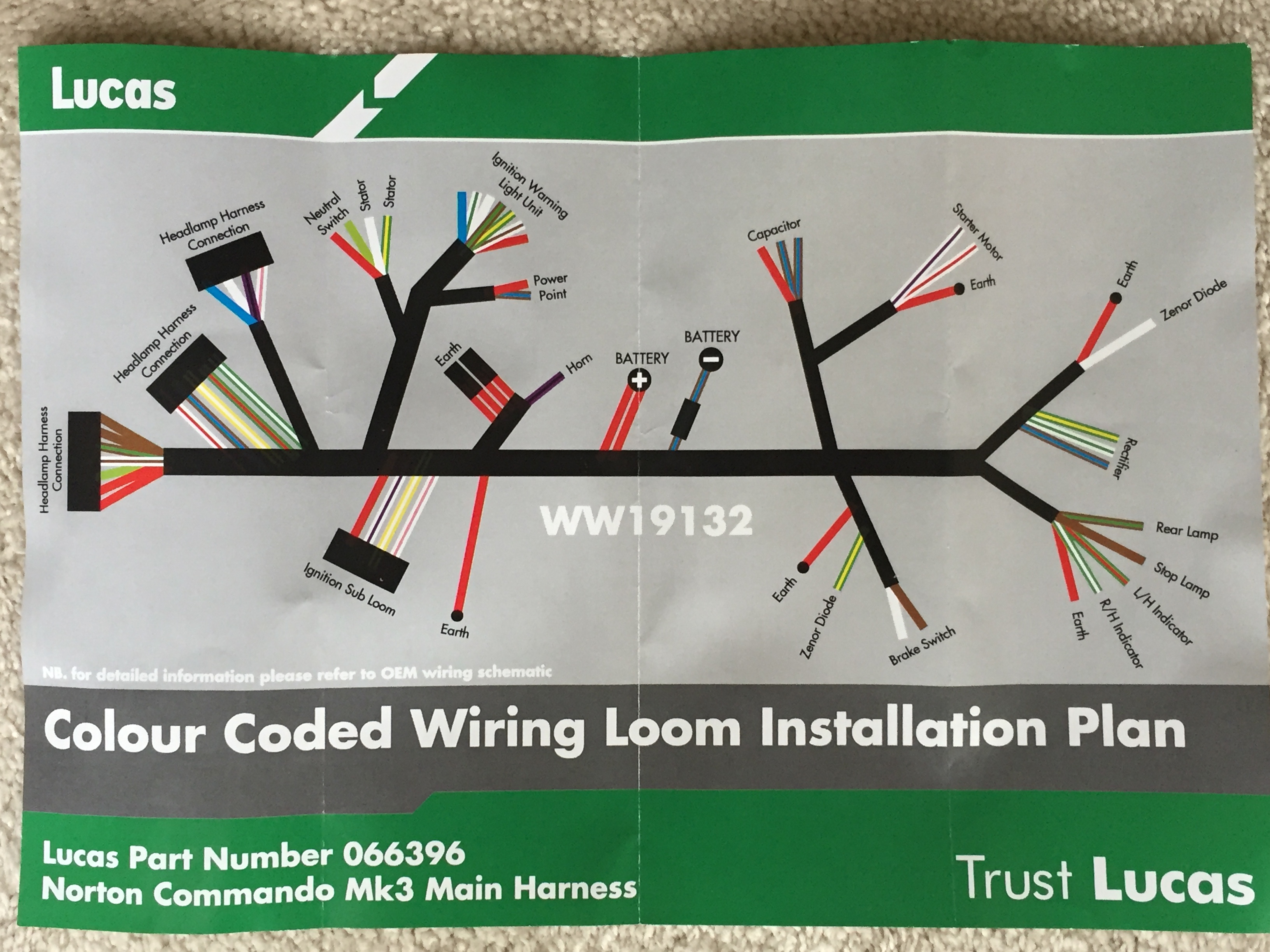
Now the wiring loom as above-It is NOT a Lucas item as Lucas failed back in the 80s, It is a part made in the Far East in a GREEN box sold by a company called Wassell with NO technical backup. I have come across several of these looms (for other bikes) so far, both had issues, one appeared to be actually dangerous! This loom for a MKIII looks quite good but it has what looks like original Zener wiring, but if you use the alternator regulator rectifiers you won't need these wires!
One way to work through this problem is refer to the original diagram and get some of the standard wiring colours in your mind, and what that colour wire does. Sticking to std colours makes it a lot easier.
aoservices.co.uk 01953884681
- Log in to post comments
MK3 Wiring Diagram
Hi Lest,
So you have a couple of 'upgrades' there:
- Boyer Electronic Ignition which replaces the factory points, condensers and ballast resistor.
- A regulator/rectifier to replace the standard two zeners and rectifier.
Your MK3 wiring therefore, will look like this:

Shout if you get stuck - there is plenty we can do to get you through this!
- Log in to post comments
Hi Lest, More harness…
Hi Lest,
More harness routing pictures. Basically it comes from the headlight down the right hand side, with branches for the ignition sub harness and engine earth before going through the grommeted hole in the bracing plate under the middle of the main spine with more branches then for the ignition warning light unit, alternator stator, gearbox neutral switch, power socket, horn and earths with branches left to the battery, regulator, blue capacitor and starter solenoid and longer branches going each side to the zener diodes on the Z plates with red earths, right hand side one also has wires for the hydraulic brake light switch. The wires for the rear light and indicators goes through the rear bracing plate with the red grommet again down the right hand side. If you are using the regulator/rectifier you pictured, the zener diodes won`t be needed.
Regards, Al.
- Log in to post comments
Re Grants wiring diagram.
Nice job you've done! Some comments on it though.
Lester, spend a couple of days to fully understand all details in the diagram. Learn the different systems. Charging, starter, ignition, lighting, indicators etc. Find out exactly what switches do in different positions. Then figure out where everything should be placed on the bike. Do ask if some part is unclear. A lot of us will happily try to make it clear. The only stupid question is the one never asked.
Notes on the diagram. Do you have a single phase (two wires) or a three phase (three wires) alternator? The regulator/rectifiers are different. Diagram shows a single phase. Those from Al Os have yellow incoming leads instead of yellow/green. I suggest adding a capacitor to enable kickstarting without battery. Al Oz can supply and tell where to connect it. Probably to the outcoming red and black leads from the rec/reg.
The earth connections are not fully drawn in the diagram. Makes it easier to read. Make certain you get them right. On a Commando a good connection between engine and frame is important. The isolastics isolates both vibrations and electricity. Throttle and clutch cables are not a reliable conductor for return current to the battery.
- Log in to post comments
Mikael - ref diagram
@mikael the diagram I included in my above post was based on the pile of parts in Lest's pictures.
I made an assumption based on these pictures, that he was going to use them!
- Boyer Electronic Ignition
- A single phase podtronics, and a single phase Boyer Bransden Power Box (obviously only one required)
I have many wiring diagrams on my site, feel free to browse and see if there is anything of interest.
For example, here is a MK3 diagram with the original components:

Hope this helps!
- Log in to post comments
Make sure the engine earth…
Make sure the engine earth lead is in place on a MK3 - the thick lead!! Do not rely on an earth coming of the head or elsewhere. Connect this thick lead at the crankcase first. Just in case you accidently hit the start button. It is most probably the most important cable on the MK3 as it could prevent your workshop filling with a Lucas fragrance.
- Log in to post comments
engine earth
Ash, you’ll see that I have dropped the small gauge red wire from the battery on my drawings leaving only the heavy gauge cable that goes to the crankcase adjacent to the starter motor.
It’s also mentioned in the notes with some other corrections.
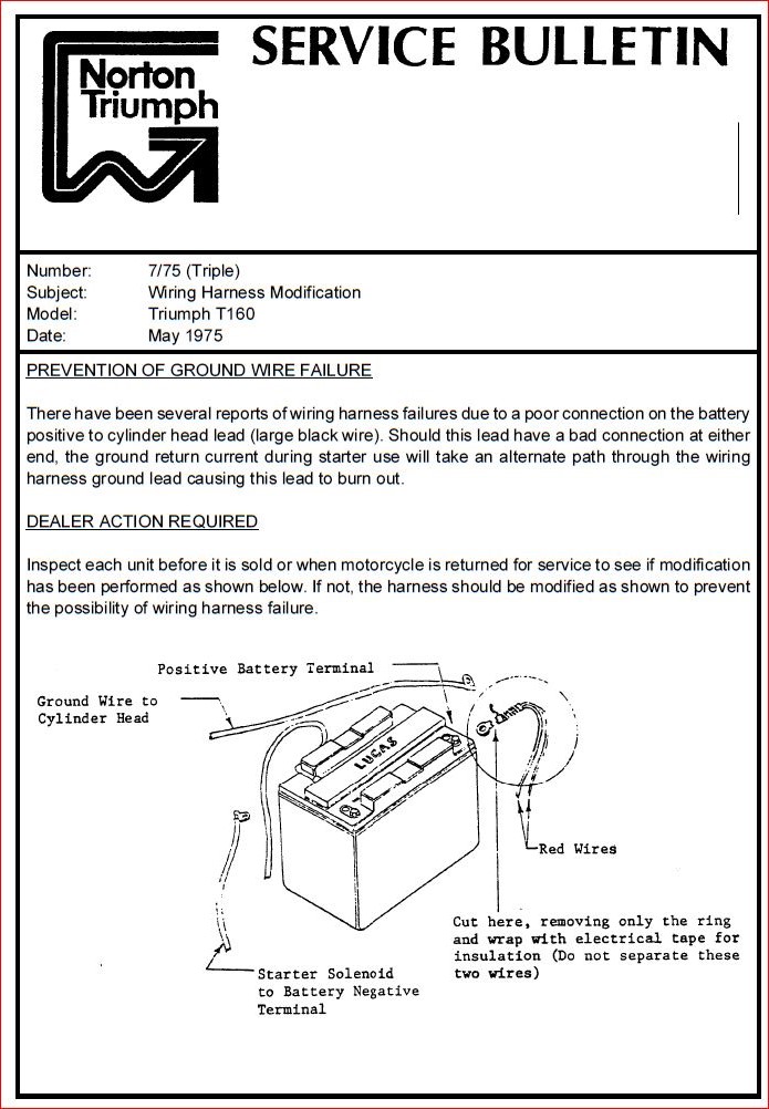
I did this as per the Triumph T160 Service Bulletin from May 1975
I understand that dealers were told to cut the wire on any Commandos they had in stock too.
- Log in to post comments
A big thank you
I have been on yet another mission and not looked at your replies for 3/4 weeks but I have just seen all the info you have kindly sent to me.
All the info & pics will be very helpful and I should be back on the project later this week so probably questions will arise soon.
Again thank you all for your valued support.
Lest
- Log in to post comments


I posted a request for any one that could assist with the wiring connections on my MK3 Commando
the previous owner did not mark up the wires when they disconnected.
The bike came with a lot of parts some new and some aged and although my area is mechanical for 50 yrs, I always require assistance with electrics and this is no exception.
If anyone could throw some light on the what the parts are in the picture it would be of great help
Regards to all
Lester Powell