
Rewiring my 99 Dominator which at some point has been converted to 12v and a modern ish regulator/rectifier fitted. The Haynes wiring diagram is very poor to say the least, there appear to be wires going to nowhere on it, ie alternator to terminal 7 on the switch?
I’m guessing where the alternator and regulator wires go to, so I wondered if anyone had a proper diagram I could follow, which would reflect the new 12v and electronic regulator layout?
Many thanks
Tim
More information would help,…
- Log in to post comments
Lighting coils
... is probably what that wire from the alternator is for. For normal running only 1 charging coil is used; with lights on the others 2 are brought in.
If you have a modern reg/rectifier then I'd expect the alternator wires to be connected as if it was a 2 wire one
- Log in to post comments
Sorry it is a 59 Dommie, it…
Sorry it is a 59 Dommie, it appears that two of the three wires out of the alternator are joined to provide 12v? The third wire is connected to the 7 terminal on the switch, which as far as I can find out, isn’t connected to anything according to the Haynes manual?
Coil ignition.
- Log in to post comments
wiring
hello Now Lucas RM21 are two wires so scrap yellow and green nearly all wires on a Norton are Negative wire as the Frame is live, Postive red wire to frame 1959 model were coil ignition and therefore have the PRSA8 switch in the headlamp so work things out from there yours anna j
- Log in to post comments
12V wiring
Please ignore above words from AJD as they are useless and confusing.
12V reg/rectifiers, these have 2 (mostly YELLOW) in put AC wires, these are fed from the alternator which is converted into a two wire by connecting the GREEN/YELLOW to GREEN/BLACK the other alternator wire is the WHITE/GREEN. If you started with the previous 3 colours then your stator would MOST LIKELY is an RM19 which was made for 6V but can easily supply 12V.
Once you have gone to 12V then the alternator no longer has any connection to the PRS8 as the regulation is fully done by the Zener or the Reg/Rect. The stator feeds the (2YLW) Rec/Rect (or Rectifier and Zener, while the output of said has Positive to Earth and Negative to the Amp-meter for battery charging. The DC from the Amp-meter (same terminal) then feeds the DC side of the PRS8 or similar light switch. ALL British alternator bikes with coil ignition follow this system.
Remember the battery supplies the coil ignition and the lights. the bike is fully functional as per and you will travel up to 100 miles before the battery goes flat-THEN and only then does the need for battery charging-alternator /rectifier etc have to be in good order to keep the battery charged.
I sell these reg/rects see aoservices.co.uk
- Log in to post comments
Thank you Alan, that’s what…
Thank you Alan, that’s what I needed to know.
Yes I have the colour wires that you mentioned, and the PRS8 switch, so I’ll give it a go over the weekend and let you know the result.
Many thanks, Tim
- Log in to post comments
A simple question i hope -wiring up a Podtronic
Fitting a Podtronic on a 650SS. All the instructions says it's simple!
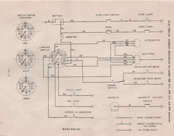
My alternator has three wires. Currently the green/yellow goes to the the bullet connector at the top of the sprung caliper thing on the switch. Instructions say that this wire now connects to one of the yellows on the Podtronic. Can I/Do I now forget that particular connection to the switch? I believe that it switches in another coil on the alternator so I probably can???
I understand that the black wire from the Podtronic (+ve earth bike) will connect with the old Brown/purple off the rectifier which goes to switch connector position 3 which in turn goes to the battery via the ammeter. That one is fine.
However, one of the double green/browns off the old rectifier goes to switch connector position 1. Does this connection get scrapped as well as it is the other wire for originally switching in another alternator coil or do I need a double connector off the new podtronic yellow to run a replacement wire to switch connector 1?
Lastly, one of the double white/greens off the old rectifier goes to switch connector position 7. Again, does this connection get scrapped or do I need a double connector off the second of the new Podtronic's yellow wire to run a replacement wire to switch connector 7? I can't work this one out?
Sadly none of this covered in the instructions. Any help gratefully received.
Wiring diag attached.
Thanks
- Log in to post comments
Basic reg/rect
The Podtronics reg/rect might be an ok bit of kit but Lowbrowcustoms.com don't know what they are on about.
The RM 19 or earlier stator has three wires. To use 12V the GRN/BLK connects to the GRN/YLW the other wire is WHT/GRN, this makes the RM19 a two wire stator in line with the RM21. these two wires connect into the two YLW wires of the reg/rect. All other alternator wires to/from the PRS8 or 88SA are removed. The RED from the reg/rect goes to Earth and the BLK becomes the BRN/BLU which feeds the battery via the Ammeter.
Further information will be available on aoservices.co.uk
- Log in to post comments
Reg/rec fitting
Thank you for the update Alan.
What did the extra white/green wire from the old rectifier to position 7 on my switch do? (see my wiring diagram)
Cheers
- Log in to post comments
VERY GOOD QUESTION
Very good question, I am glad you are watching. The GREEN/WHITE is actually from the Alternator and goes to SW7 the other side of the rocker part of the switch goes to the GRN/YLW on the alternator SO when the switch is in the off position the WHT/GRN and the GRN/YLW are connected together. This shorting out of part of the alternator reduces the alternator output-no lights-ignition only.
Once you put side lights on this switch function becomes open circuit partially increasing the alternator charging. All part of 6V in the early days (late 50s). Later on, from the factory this function was dropped, I would have thought to increase the charge in Ignition only position.
Very few people have even seen this function let alone worry about it. This was one more function of the PRS8 and shows why we had 19 terminals!
- Log in to post comments


More information would help, what year is it ?, mag or coil ignition. With modern regulation there is no need for a switch in the charge system ,do you have an ampmeter?.