
Hello, all.
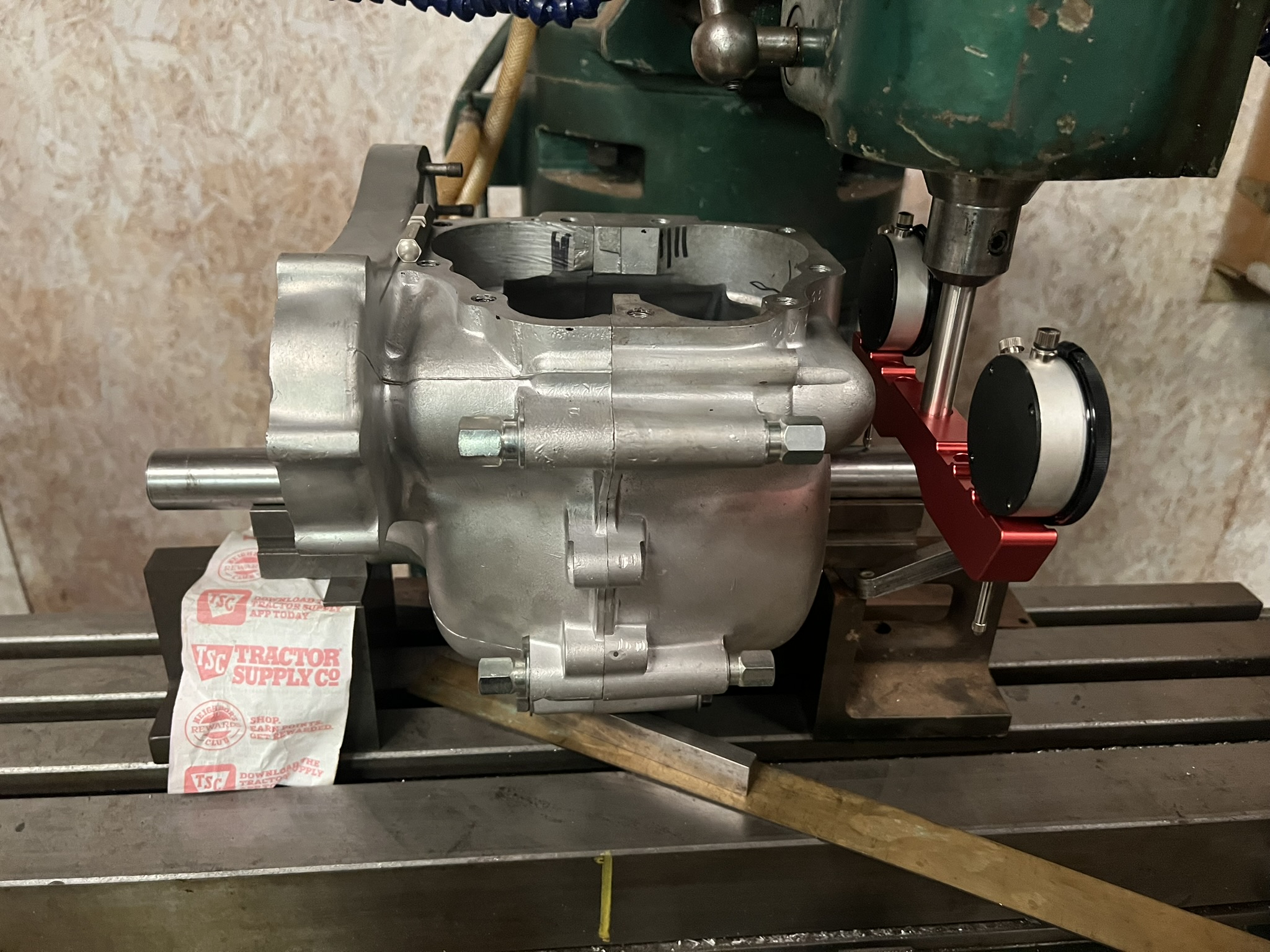
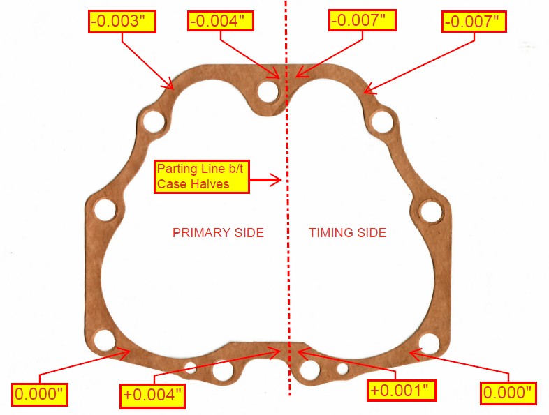
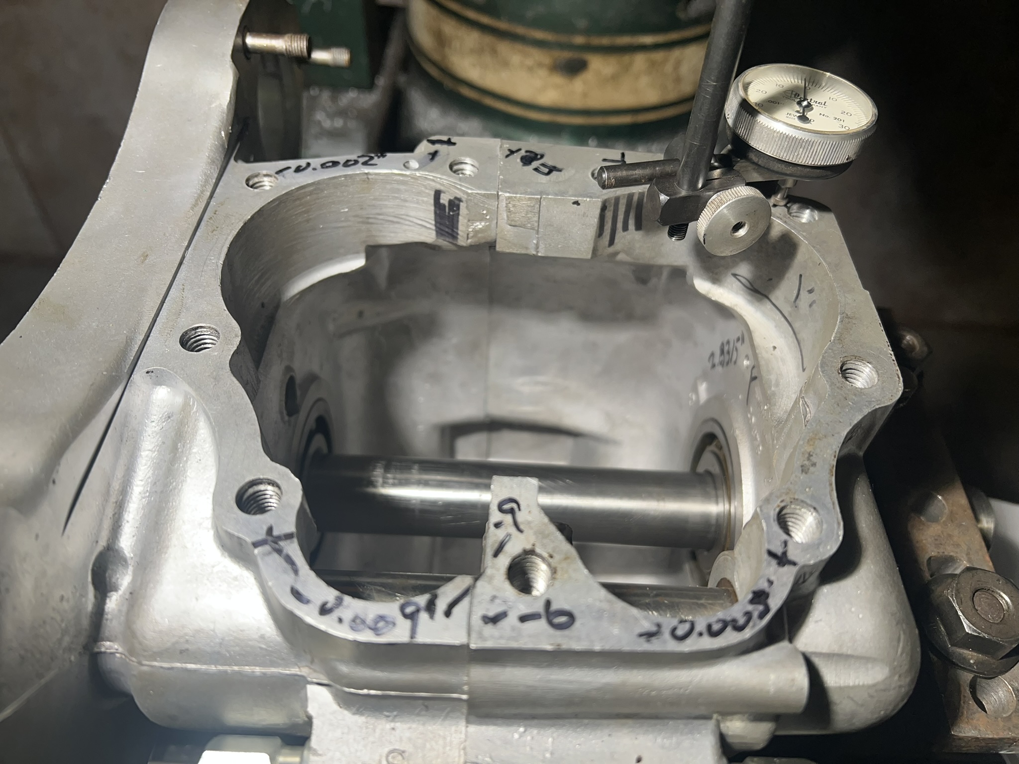
I have a set of cases in the mill right now that have a total variation across the deck of 0.013" which can be seen in the image below.

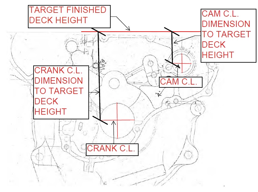
I would like to bring this back into spec. as much as possible, so I am looking for some reference dimensions, namely, the centerline dimensions from the camshaft and the crankshaft to the target deck height. This is shown in the image below.
Does anybody have these dimensions on hand that they can share?
Thanks!
-Robert
Have you clocked the…
- Log in to post comments
Hi, Paul. Thanks for the…
Hi, Paul.
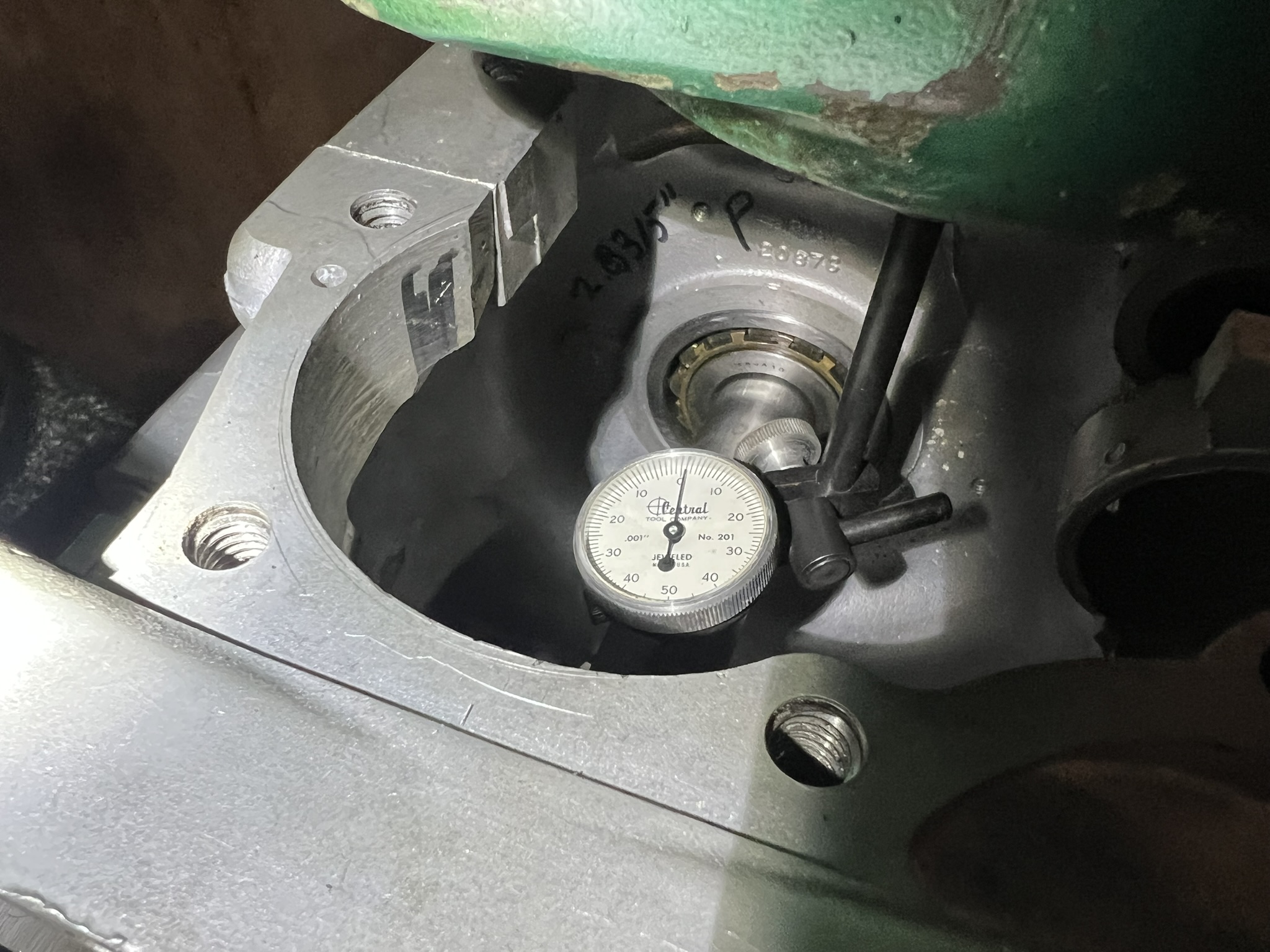
Thanks for the response. I have done what you have suggested. This is how I know I have an issue.


If you look at the third image above, you'll see that I have a to variation of 0.013" across the deck. I do not consider this variation to be minor.
Everything critical in the engine is referenced from the deck; when the cylinders are bored, they are bored relative to the bottom of the barrels. Because the barrels meet the face of the case deck, the crankshaft should be dead parallel to the deck or else the barrels will be askance and you will lose a lot of power to unnecessary drag with the added disadvantage of increased wear.
Finally, you can have similar issues if the barrels aren't correctly configured fore and aft. A good reference to achieve this correct "ideal plane" would be from the factory blueprints which should provide the centerline dimensions I am seeking.
Any input on this front that you could offer would be greatly appreciated.
Thanks,
-Robert
- Log in to post comments
Skim
Without giving it too much critical thought I would say you're governed by the lowest dimensions.
The 0.000" on both sides at the rear which appear true to the left and right datum of the dummy crank and the -0.007" at the right front.
Can you not rotate the cases to split the -0.007" difference between the front & rear to -0.0035" lock it down and skim it flat?
Will probably be as good as most and if they're 850 cases, they use sealant without gaskets as Paul suggests.
The DIY fix for nice flat faces on my Mk3 was to bolt the cases together and lightly hand skim them on a flat bed with 240 wet & dry. Mainly cosmetic to clean up the surface, no obvious mismatches.
Aligned perfectly using straightedge and eye with crank fitted and never any leaks sealed with Permatex Ultra Grey sealant and a good PCV valve.
- Log in to post comments
Hi, Neill. Thanks for the…
Hi, Neill.
Thanks for the feedback.
I am governed to an extent by the lowest point, but what I don't know is what's been done before and if by splitting the difference I might be going in the wrong direction. And while I could certainly cobble the whole affair back together and use any number of sealers, but that's not how I operate, and I'm not looking to be "as good as most."
My goal with my engine builds is to "blueprint" the engines, at least as a starting point or baseline condition. By "blueprinting," I mean to bring the engine as close to the original specifications as intended by the engineers.
With the goal of blueprinting this engine, the missing piece is the answer to this questions I have posed. Perhaps it would make more sense for me to reach out to the archives to see if they have any of the historical drawings on hand.
Thanks again!
-Robert
- Log in to post comments
Blueprinting
I blueprinted most parts of my engine (and most of the bike) but more to my own specs and those of the aftermarket parts I used. Stock was a basic guide, but many things were changed to make it all work together, a far more important objective than rigidly following set numbers or tolerances.
The original engineers certainly couldn't afford to spend time fettling to the same degree on production bikes although the race department no doubt knew every trick in the book.
Interesting and fun, especially in the cylinders, head, carbs and final tuning, very rewarding .
You're in for a shock if you have a Mk3 and want to keep the combustion chamber volumes and compression ratio close to the original specifications!
Keep us updated on progress.
- Log in to post comments
Hi, Neill. You get it! Early…
Hi, Neill.
You get it!
Early in my career I built engines for Rolls-Royce and Bentley, and our work was held to the highest standard. As a result, every engine I build is built to that level of care not because it needs to be, but because I enjoy building engines. The old saying about the journey being as important as the destination comes to mind.
Like you, I ultimately will vary from the stock specs, but the first step is to understand the stock specs before introducing any changes. In fact, very little of this engine will be stock, but whenever one builds a house, they should start with a sound foundation.
And while the production line machines would never receive such care, the competition shop most certainly lavished their machines with such attention. We're all familiar with the way the engineers and staff hand-picked the best-of-the-best from the production line to make the Production Racers.
On a British parallel twin, the cases could be considered the foundation, and the deck can be viewed as the absolute reference point. For example, the lateral element of the deck needs to be as parallel to both the CL of the camshaft and the crankshaft. If not, you will see variations in your valve events as well as premature wear along the cylinder walls.
When considered from the fore aft perspective, one must also consider this relationship or risk accelerated cylinder wear or possibly "negative" desaxe. On a Triumph which has an exhaust cam ahead of the crank and an intake cam aft of the crank, you also risk encountering sub-optimal valve geometry.
Moving up towards the head, we then address the barrels. Before boring the barrels or performing any other operation on the them, I first mount the base in a specially made torque plate and fasten it in position using stock hardware and torque specs. This torque plate is also precision ground to a consistent thickness so that once the barrels are fixtured to be bored, I know that the new bores will have a 90 degree relationship to the case deck.
And, as if this were not enough, I also install a torque plate on the top of the barrels where the head would normally mount. The reason for this is that the studs/bolts that go into the barrels introduce localized deformations in the barrel. This is not theoretical and can be measured.
Finally, with both torque plates in place, the cylinders can be bored with confidence that the geometry is as good as it can be.
With the bottom end together, the head work is pretty straightforward. I do CC the heads, measure for squish (or quench!), adjust for target compression, usually by using head gaskets of varying thickness, ensure valve-to-piston clearance, cut a multi-angle valve job, etc., etc.
Finally, regarding your comment about Mk. III cases, these cases are for a very early 1968 Commando. Regardless, if they were for a Mk. III any skimming from the deck on the cases could be made up with a base gasket.
Thanks again for the feedback!
-Robert
- Log in to post comments
Ways and means
Robert
very interesting reply. We both read from the same book but get the desired result in different ways. I also enjoy building, modifying and tuning engines but also the rest of the bike. Only one of too many hobbies these days.
Building is enjoyable but how it performs riding or driving on some of the best roads in the UK and Europe is the ultimate test...
My original trade was a machinist but I invariably use effective DIY methods with simple tools and whatever is at hand. Previous AutoCad and Pro Engineer drawings now replaced by hand drawn notes as the software expired.
Some important machining subject to various configurations like cutting valve seats I do myself but reboring, crank machining, balancing etc are farmed out. Smaller items are done by a talented and meticulous neighbour who has a lathe and mill.
What I meant regarding the Mk3 head was the quoted 8.5:1 compression ratio is way off. Steve Wilson in the Commando section of his Norton Motorcycles book mentions actual figures of 7.8:1 to 7.9:1. Mine had the original std Hepolite pistons sitting below the deck and an RH4 head. Compression ratio measured 7.7:1 with the (leaky) 1mm copper gasket previously fitted.
I had +0.040" JE forged flat top pistons made (no valve reliefs) bought a pair of Carrillo rods and skimmed the cylinder top for zero deck height. Both pistons were dead flat to each other and the deck at TDC with the cylinder base sealed and bolted down. Even with the bigger pistons giving a true 850cc, compression ratio was only 8.5:1 with the standard 1mm composite gasket.
No way this particular engine could ever have been 8.5:1 from the factory so the designers intentions disappeared between the drawing board and engine assembly.
The actual sealant line on the 240 wet & dry hand skimmed cases revealed on a recent +0.060" JE rebore, is very thin. More a discolouration, but never leaked in the 28k miles since it was last done. RH4 head was replaced with a Fullauto in 2017.
I aimed for up to 9:1 max compression without skimming the head to give the starter an easy time, keep the standard pushrod length and maintain good valve train geometry following Steve Maney's advice. His std length chrome moly steel pushrods weighing the same as O.E alloy ones are used, perfect for stable valve clearances in the cast iron cylinders.
I agree a solid foundation is necessary in the bottom end but the critical detailed work to make it all sing is in fuel flow mods, valve train, head, carburation, ignition and exhaust. Far from straightforward to be honest and a lateral thinking hot rodders approach is very helpful.
Your setup is crying out for something like Jim Schmidt's Carrillo/JE piston long rod set and BSA type cam followers by the way.
Cheers
Neill
- Log in to post comments
Hi, Neill. Just as we both…
Hi, Neill.
Just as we both read from the same book but get different results in different ways, it would appear as though we also arrive at the same destination, albeit from radically different points of departure.
And, without going into the details of each and every one of your points, I fully agree that this project calls for some of Jim Schmidt's lovely kit, especially the long rod set, lightweight pistons, and BSA-type cam followers and cams, as you have sagely suggested.
However, I view these tasty bits as stage two modifications to be incorporated at a later date into this initial build. The first go round is a "proof of concept," but the second go round will incorporate some of the items that you have mentioned, as well as some yet-to-be-named surprises that will surely engender some spirited debate amongst the ranks.
With warmest regards,
-Robert
- Log in to post comments
Creativity & Innovation
Looking forward to further progress! RR style attention to detail with creativity and innovation. Glad you chose the Commando engine as your project, I really think it's one of the all time greats once the creases are ironed out. Keep us informed of progress.
Cheers
Neill
- Log in to post comments
Hi Robert, Just sent you an…
Hi Robert,
Just sent you an email with a drawing. It may be no use whatsoever but it is the best I have.
Regards
Tony
- Log in to post comments
Thanks, Tony! You were…
Thanks, Tony!
You were reading my mind! I think this should work a treat.
Many, many thanks!
-Robert
- Log in to post comments
It looks as if each side is…
It looks as if each side is planar to within 0.001 on the right and 0.002 on the left. Perhaps the two halved didn't leave the factory together? There is a step of 0.003 between them. So you need to establish the exact height (or heights) of the plane faces of each half relative to the crank. Presumably you should insert a mandrel through the main bearings to find out what's up. If they do match - shouldn't the cases be finally tightened together with the barrel (or another flat surface) is in place?
- Log in to post comments
Hi, David. YOU WROTE: It…
Hi, David.
YOU WROTE: It looks as if each side is planar to within 0.001 on the right and 0.002 on the left.
The left is off by 0.008" front to rear as is the right.
YOU WROTE: Perhaps the two halved didn't leave the factory together?
You are correct. The cases are mismatched, but the primary side case is is a "matching numbers" case, hence the desire to keep these cases.
YOU WROTE: There is a step of 0.003 between them.
Agreed.
YOU WROTE: So you need to establish the exact height (or heights) of the plane faces of each half relative to the crank.
Exactly. This is what I described in my initial post, how I arrived at the values I provided, and why I am seeking CL dimensions for the crankshaft and camshaft.
YOU WROTE: Presumably you should insert a mandrel through the main bearings to find out what's up.
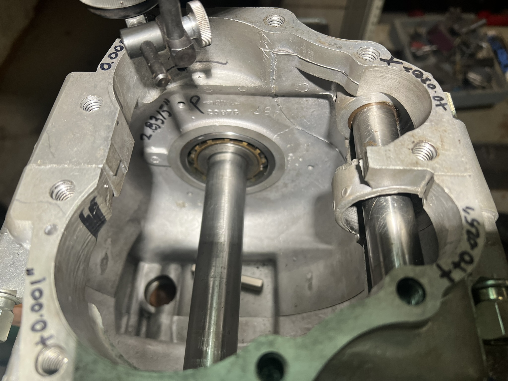
Agreed. The mandrel is the big shiny thing running through the bearings where the crank goes and is resting on the V blocks in the pictures attached to my post above. To provide an extra measure of security, I also placed a mandrel where the cam goes. Both mandrels turn freely which tells we that the alignment between the cases is spot-on. The difference on the deck is because the cases did not leave the factory together as you had suggested.
YOU WROTE: If they do match - shouldn't the cases be finally tightened together with the barrel (or another flat surface) is in place?
The cases are mismatched, but the primary side case is is a "matching numbers" case, hence the desire to keep these cases.
-Robert
- Log in to post comments
barrel+head surfaces
Robert,l am also interested in what you find when checking th head gasket surfaces -R.E.
"theworldsstraightestcommando son of P11"
Sorry that l can't send th highlighted e-dress,l am still trying to learn "folders":
- Log in to post comments
Hi, Barry. The head and…
Hi, Barry.
The head and barrel are from different machines than the cases, but the barrels have been bored, the top and bottom contact faces are dead perpendicular to the bores, and the mating surface on the head is as close to perfect as I have ever seen and does not appear to have ever been cut or abused in any way.
Thanks for your enquiry!
-Robert
- Log in to post comments
The above makes no odds, the…
The above makes no odds, the cases are well located together and 0.007'' is nothing to remove from across the barrel face. The worst that is going happen is an increase in CR by a small amount. If the head and or barrel has been skimmed to within an inch of their lives then you may encounter issues later in the build, you'll also need to make sure the barrel tappet tunnel is not ridged as the tappets will travel further up the tappet tunnel and any wear ridge in this area from previous use, this will need to be removed or the tappets adjusted accordingly.
The case that is -0.007'' may have been used in the past with its correct mating case and I doubt the owner even noticed that it gave slightly increased CR.
- Log in to post comments
Hi, Ashley. I agree entirely…
Hi, Ashley.
I agree entirely with your observations.
Thank you for sharing them.
-Robert
- Log in to post comments
Crankcase dowels
Ashley assumes the are in place. I don't share his view that the dowels guarantee alignment.
In a similar situation, and finding a slight step between the flat top surfaces at the rear.
Loosened crankshaft securing screws slightly. Placed barrel onto crankcases and tightened it down. No gasket. Tighten crankcase fasteners, loosen barrel fixings, re tighten crankcase screws. Perfectly flat and aligned top crankcase surfaces.
On inspection the tubular dowels are easily deformed, not in too deep, and easily put in off square.
You might consider Robert.
Peter
- Log in to post comments
Hi, Peter. In addition to…
Hi, Peter.
In addition to the dowels being in place, I have installed a precision ground solid SS bar in the main bearing where the crank belongs and another precision ground solid SS bar in the bushing where the cam goes. Both rotate freely which suggests that the cases are well aligned and not "clocked."
I should ass that the cases are a mismatched pair, but the primary side case is is a "matching numbers" case, hence the desire to keep these cases.
Regardless, Mr. Ripley was able to provide me with the information I needed.
Kind regards,
-Robert
- Log in to post comments
Only one remaining comment…
Only one remaining comment...you say that both are out by the same amount (0.008") front to rear. So if you rotate your reference plane by 0.008", they are 0.000" in that respect. So where is the horizontal reference plane? The only one I can think of is the base of the crankcase around the drain plug. I doubt if that is reliable, nor if it is important that it be parallel to the top surface(s).
Nonetheless it seems you have the job in hand. Although I don't know how the design dimension will help unless your cases are over height from the factory and you can reduce all surfaces to the correct plane. Or go lower and restore height with a compression plate and increase the chance of oil leaks.
- Log in to post comments
Hi, David.Thanks for…
Hi, David.
Thanks for sharing your thoughts.
YOU WROTE: Only one remaining comment...you say that both are out by the same amount (0.008") front to rear. So if you rotate your reference plane by 0.008", they are 0.000" in that respect. So where is the horizontal reference plane?
The horizontal reference point, as described in my earlier posts, is an imaginary plane that is dead parallel to the "dummy" crankshaft and camshaft. The "dummy" crankshaft and camshaft established this imaginary plane along the lateral axis. However, the piece of information that was missing from my analysis was the factory's target dimension from the CL of the camshaft and the CL of the crankshaft. This is the information Mr. Ripley so graciously provided.
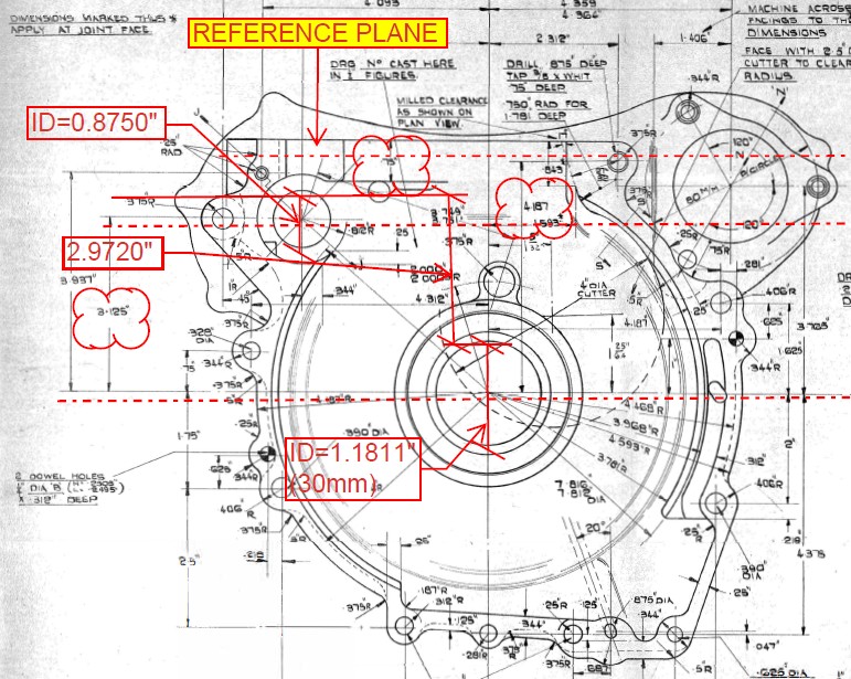
Because the factory specified that the CL from the crankshaft to the camshaft was to be 3.125", I removed the radius of the crank journals and added the radius of the camshaft to the factory's target value to determine the vertical displacement from the top of the "dummy" crankshaft to the top of the "dummy" camshaft. With this in hand, I was able to determine how to set the cases fore-to-aft by pivoting the cases around the "dummy" crankshaft and carefully measuring the relationship between the two shafts until I achieved the desired displacement.
The values I originally used were somewhat arbitrary as I originally fixtured the cases such that the trailing edge of the deck on the timing and primary side was zero, and then I swept the other dimensions. This was not done to determine where the plane was, or should be; it was done to determine the overall relationship between the datum points. I only chose them as a reference point because the trailing edge of the deck on the timing and primary side was at zero. Because I knew these points to be in A correct, but not necessarily THE correct relationship to the plane, I chose them. I could have chosen any of the datum points to be the "zero" reference point, but the overall relationship between the datum points would not have changed.
To prove this point, as you can see from the chart below, I adjusted the values in each row such that the zero datum changes from one column to the next.
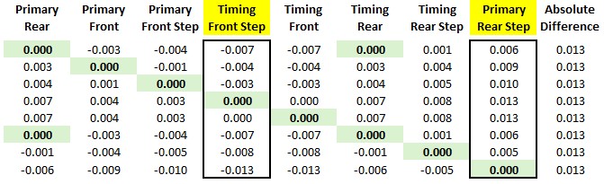
You can see that, despite the arbitrary "zero" reference point, the maximum difference is always between the front "step" of the case on the timing side and the rear "step" on the primary side.
And while I understand that this difference is likely because these are not matched cases from the factory, regardless of the cause, what does not change is the absolute value of the difference between those two data points. It is always 0.013" in this case and will generally remain in that range. (The only exception to this would be if I were to radically rotate the cases around the axis of the crankshaft, for example, if I were to rotate the cases, for example, 90 degrees.)
YOU WROTE: The only one I can think of is the base of the crankcase around the drain plug. I doubt if that is reliable, nor if it is important that it be parallel to the top surface(s).
Nonetheless it seems you have the job in hand.
I did consider this and concluded that the base of the crankcase around the drain plug is a reference plane, but only in theory, so its practical use as such is approximately zero.
As you can see from the photos I have provided throughout this thread, I went to considerable lengths to secure the cases such that the "dummy" crankshaft was dead parallel with the mill table and therefore dead perpendicular to the quill. Even the piece of paper you see to the left in the picture below was intentional, as I didn't have any cigarette papers on hand to dial in the shims.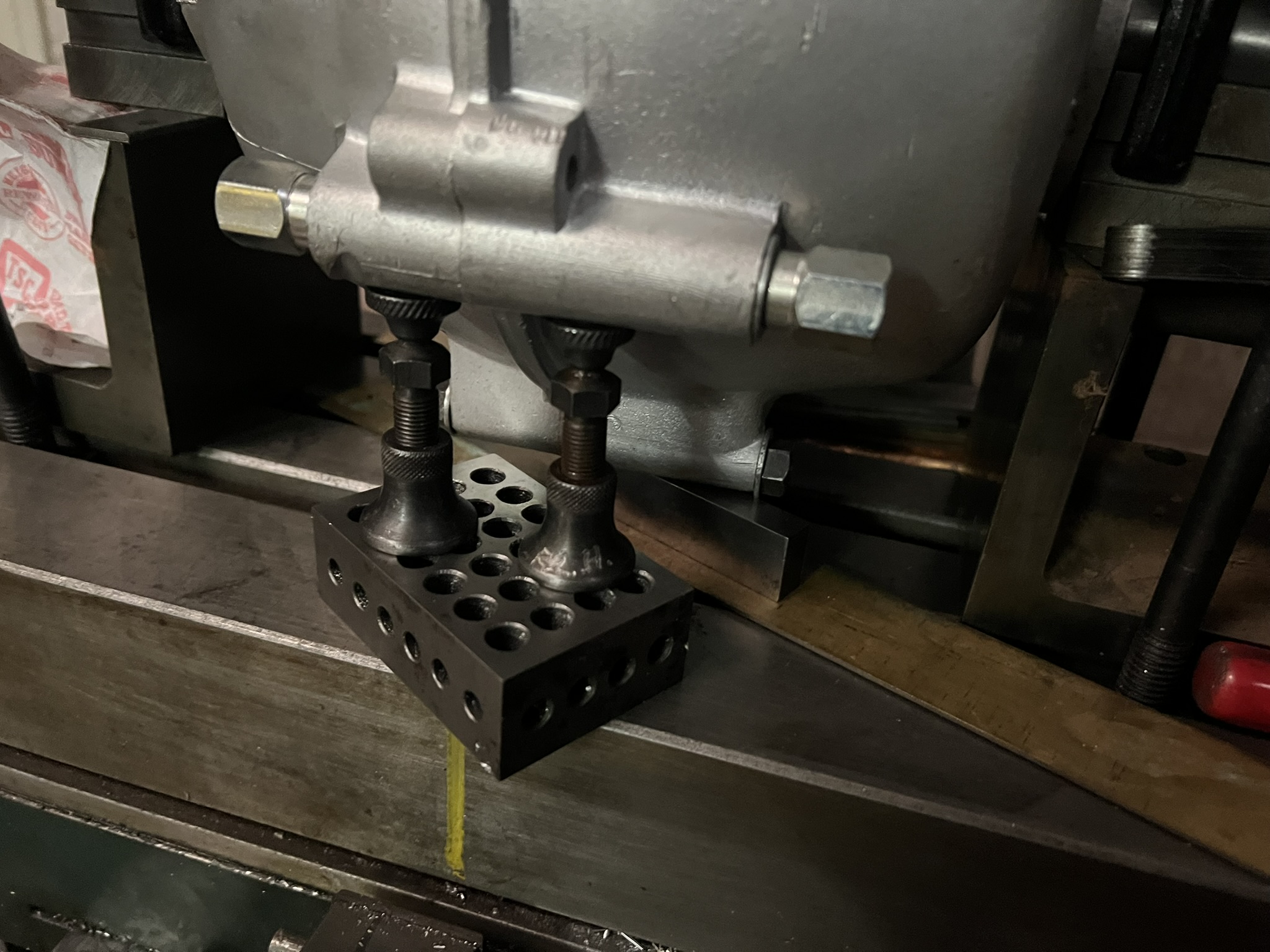
I suspect that once the deck was milled, its surface was then used as a fixturing face to bore and mill the flat for the drain plug before threading the hole. But, because it has such a small footprint, its use as a canonical reference plane would be questionable at best.
YOU WROTE: Although I don't know how the design dimension will help unless your cases are over height from the factory and you can reduce all surfaces to the correct plane.
I don't know if the cases are over height from the factory or not, but it's also not relevant, at least not at this level of analysis. Now that I know where the target plane lies, I will use the lowest point on that plane as my zero reference and go from there. This approach ensures that I remove the minimum amount of material needed to achieve my goal.
YOU WROTE: Or go lower and restore height with a compression plate and increase the chance of oil leaks.
While oil leaks are often a concern, I am not overly concerned about them in this application. Instead of having a planar surface, namely the base of the cylinders, mating with a non-planar surface, namely the case deck as it exists at present, I will soon have two truly planar surfaces mating. I prefer the latter of these two options by far.
Once I go up with the engine, I can check to see if the 0.013" I have skimmed from the decks has any appreciable effect on the compression ratio, pushrod length, valve geometry, etc. Spoiler alert: It won't!
But, assuming it did, I could use a base gasket along with Wellseal, Hylomar, Gorilla Snot, or whatever sticky stuff you have on hand, to adjust the height of the barrels. If I don't need to adjust the height, I am still not concerned about the potential for leaks, as I will install a PROPER breather to the crankcase that will place its pressure at a value slightly lower than the ambient atmospheric pressure. My experience has been that reducing the crankcase pressure gets one 90% of the way to eliminating the all-too-common leaks on our beloved parallel twins.
I appreciate your considered thoughts and collaboration.
Kind regards,
-Robert
- Log in to post comments
If anything avoid the CR…
If anything avoid the CR being low. We run a MK3 with Omega forged pistons we had made and these are designed to have a CR around 10.4:1 and it starts just as easy as any of our Commando's using pump fuel.
It is also not surprising that some find what Norton claimed in the 70's is not what they find in reality, back in those days the manufacturer could claim what they liked and get away with it.
- Log in to post comments
Hi, Ashley. Your comment…
Hi, Ashley.
Your comment regarding the CR is wise counsel.
I added the comment about using the base gasket as a variable for the record, more than anything. If someone is having issues in the future and comes across this thread, I wanted to put this out there.
I plan to run an SS cam in this engine, so my target CR is something around the 10:1. Once I get the bottom end together, I can turn my attention to dialing in the CR.
Kind regards,
-Robert
- Log in to post comments
One more thing...
As we are discussing the relationship of the barrels to the bottom end, I thought I would share a topic of interest over on this side of the pond.
Jim Schmidt is doing some research into desaxe on our Commando, and by extension, Atlas engines. This thread can be found here, and a short video can be found here.
Enjoy!
-Robert
- Log in to post comments


Have you clocked the cylinder base for this engine?
Have you bolted the two together and checked for gaps with feeler gauges.
Seems like a lot of trouble to go to with little to gain that can't be solved with modern sealants and gaskets.
But hey, if this is an exercise in seeking perfection, please keep us informed as to when you eventually get te bike on the road.