
My Atlas is not charging and everything appears to be wired running correctly, the rotor centered in the stator. Would anyone have any suggestions?
Thank you in advance
charging problem
- Log in to post comments
Did It Charge?
I received the bike not running, so I can only guess that it did charge sometime in the past. What can I look for in grounding?
- Log in to post comments
The rectifier has 3 or 4…
The rectifier has 3 or 4 terminals, the 3 terminal type earths through the central bolt to the frame and then back to the battery (ie not reliable and prone to failing from corrosion). Modern 4 terminal one have a dedicated earth terminal that has a wire which can either go to frame or battery terminal. If you have a 4 terminal ground to frame then modify to go to battery terminal, normally positive unless a DPO have converted to negative earth.
- Log in to post comments
I had a similar issue with…
I had a similar issue with my Atlas a few days ago, see post in the Electrics forum under ‘Podtronics conversion not working’ - there are some helpful hints by John and Alan and some test procedures to follow. A bit more information might help, ie. what rectifier and regulator you are using, switch, type of alternator (2/3 wire) etc. If you got the bike as a non-runner there could be wiring issue on the charging side or at the switch end, even though everything appears to work.
- Log in to post comments
Electronic regulators can be…
Electronic regulators can be wrecked if fitted to the wrong battery polarity. You should have positive (red) earth, but people change them sometimes, perhaps when fitting Electronic ignition (or radio...!)
- Log in to post comments
Where To Look In The Library?
Could someone point me as to where to look in the library for John and Alans test procedures?
My alternator has 3 wires and is using a Podtronics unit, so there is no rectifier or zener diode.
- Log in to post comments
What alternator has it got?
Does it have a three phase alternator or a three wire single phase one. The way to check is count the poles in the stator. A single phase one has six poles, a three phase one has nine poles. It might be a mismatch of fitted components.
- Log in to post comments
Check alternator
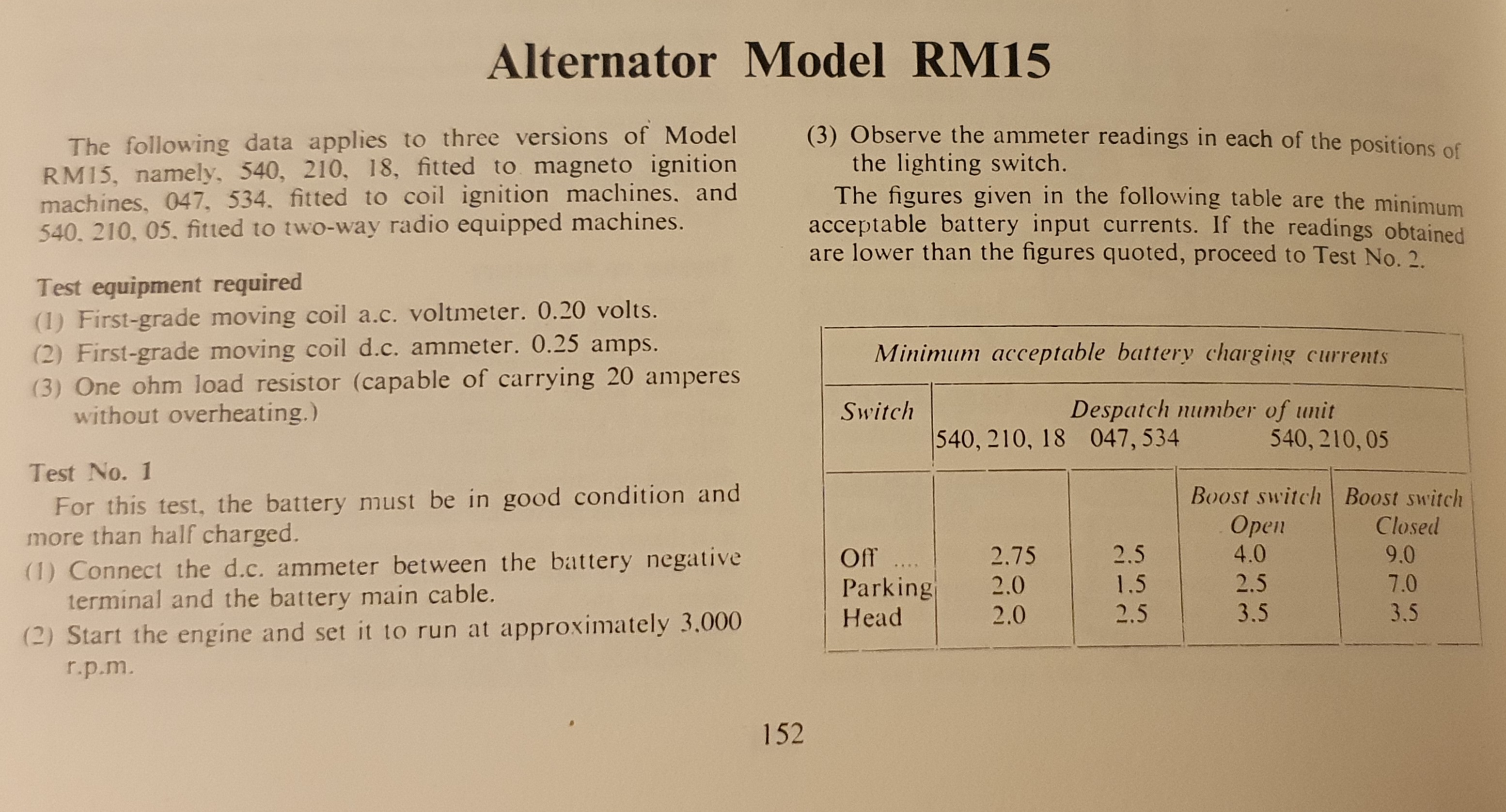
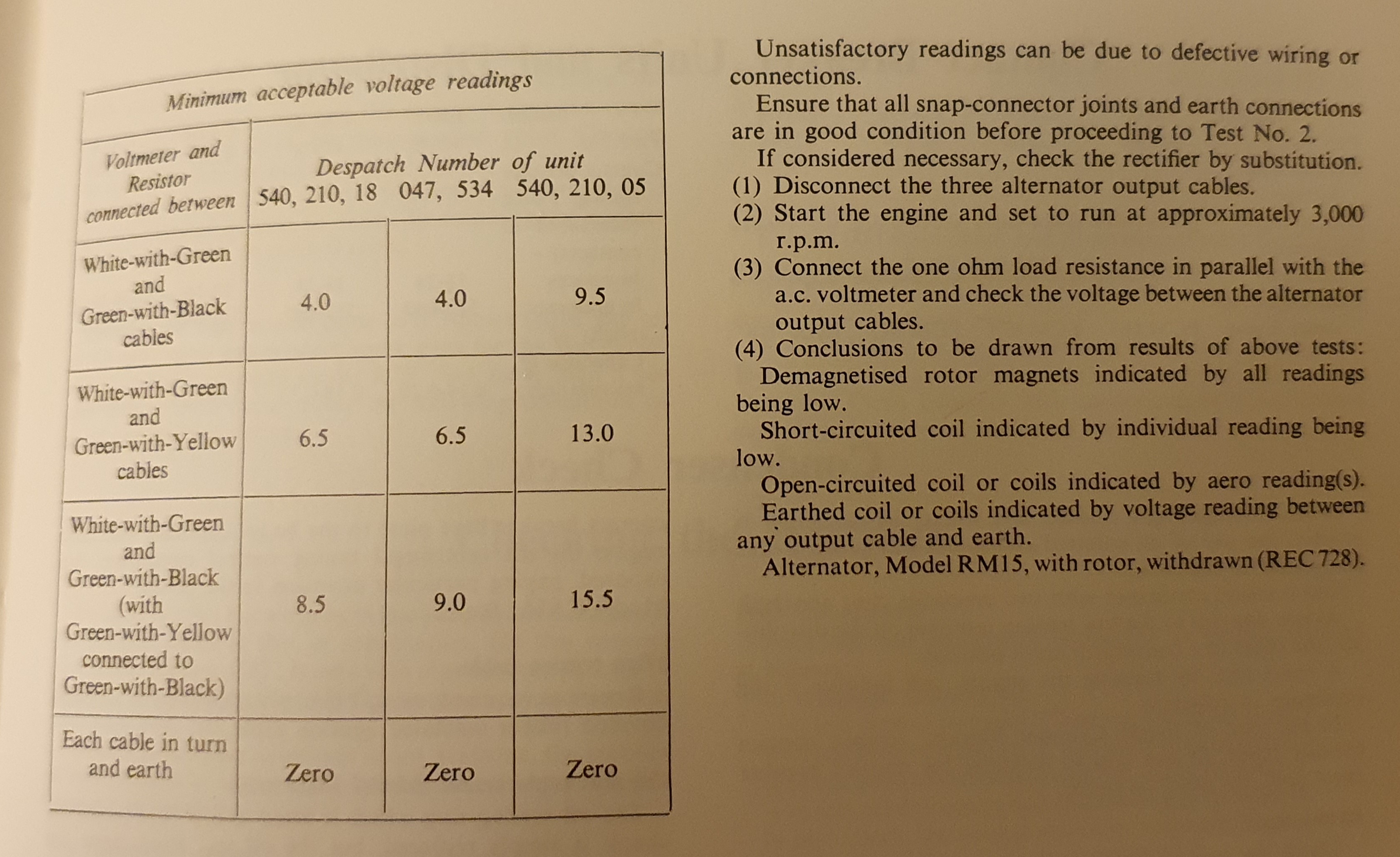
Has the alternator got continuity between the windings if its got 2 or 3 wires (single or 3 phase) check for resistance between wires. Should get a small resistance. Also check if any of windings are going to earth, they should be totally isolated. If they are going to earth the windings are shot. If everything is OK test volts output when running at leads before regulator, you should be getting high voltages ie lot higher than 12v. If volts are good then alternator is OK.
- Log in to post comments
Test procedure
Hi Jim,
Check this post in the Electrics forum with some test suggestions by John and Alan: https://www.nortonownersclub.org/node/13356 . The problem in my case was not the PODTronics unit but my dodgy wiring at the switch.
In addition to the above, use a good automotive meter to check, start at the alternator side. Check the alternator stator outputs with a test lamp (two headlight bulbs wired together or a 100W resistor wired to a test lamp) - many meters don’t do AC! Then check the DC output between the BLK and RED Podtronics output wires, again a bulb will give you a basic idea. A bulb is simple and gives you a basic idea, but Paul’s check is a bit more detailed. Re-check all your wiring at the switch (my issue was an alternator wire wrongly attached to a 41SA switch), at the Ammeter and battery. After that, follow the tests in the forum above.
- Log in to post comments
Follow Al Osbournes advice
Go to http://aoservices.co.uk/ on the web and click on the orange box in the top right hand corner marked 'electrical advice and info' What is the history behind this bike? Did you buy it fresh from restoring? Or from a friend etc
- Log in to post comments
This Has A 3-Wire Stator
The stator has three wires coming out of it. A green/yellow, a green/black, and a white green.
The Podtronics unit has two yellow wires, one black wire, and one red wire.
- Log in to post comments
The green/black and green…
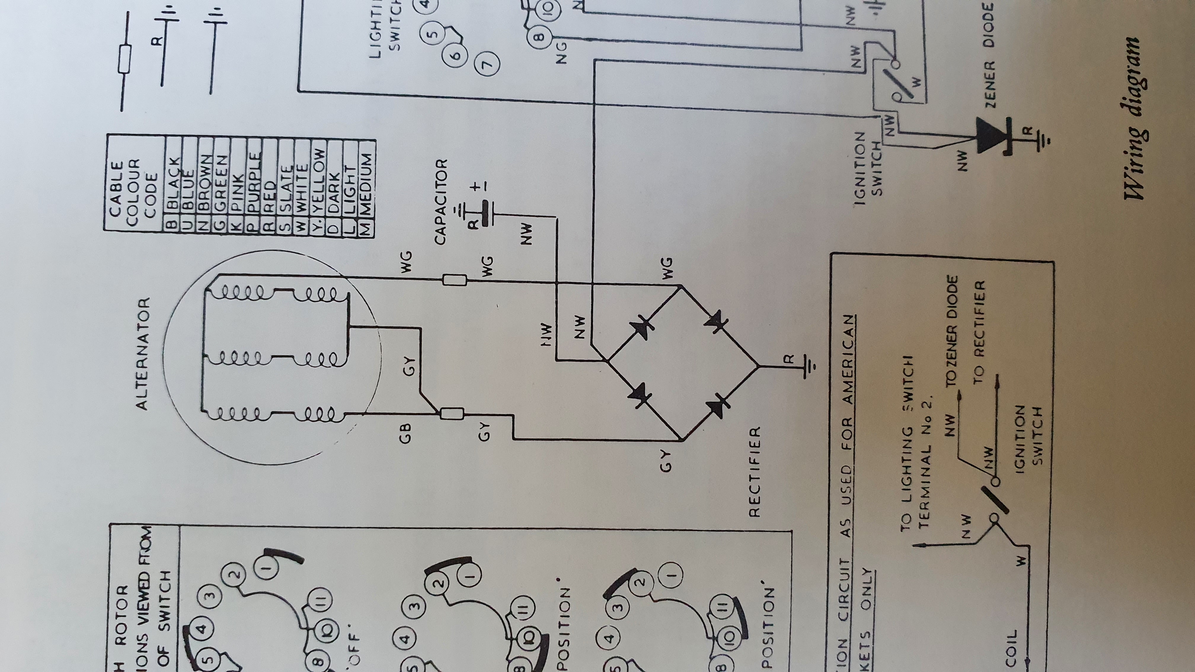
The green/black and green/yellow should be joined. That's one side of the AC generator. The white/green is the other side. Each side goes to one or other of the yellows. The red should be +ve, and black -ve.
- Log in to post comments
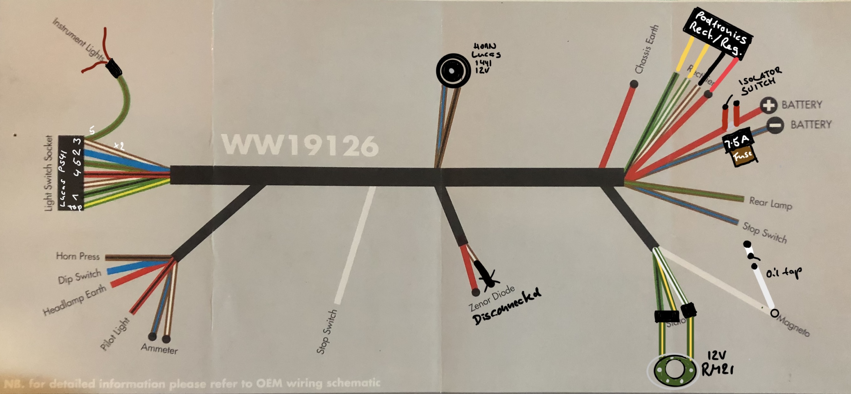
Modern wiring diagram might…
Modern wiring diagram might also be of help, see attached - assuming you have similar wiring harness, magneto and similar main switch… Only difference are the stator wires
- Log in to post comments
Atlas Not Charging Continued
The green/white goes to one of the yellows on the Podtronics and the green/black goes to the other yellow of the Podtronics. The green/yellow goes to the light switch socket according to Holger’s and my wiring diagram. My wiring harness is new and that’s where the green/yellow is going. That is curious.
Checking between all 3 leads of the stator using an ohmmeter shows it going from 1.4 ohms to 2.8 ohms. I do not know the spec on this.
Checked the Podtronics using the ohms/diode setting to check the diodes and this shows the diodes to be bad. I cannot confirm this since there is not any instructions about how to check it on the internet.
- Log in to post comments
You don't need the light…
You don't need the light switch to cut out part of the alternator if you have a modern rectifier. You need the same two outputs as Holger's diagram shows for RM21 by joining green/black with green/yellow to provide one of the two outputs so it behaves like RM21.
- Log in to post comments
Thanks for pointing this out…
Thanks for pointing this out, I now see to join the green/black with the green/yellow to provide one of the two outputs so it behaves like RM21 in Holger’s diagram.
Doing an ohm check on the three leads coming out of the stator ranges from 1.5 ohms to 2.8 ohms, would anyone know the spec on this?
- Log in to post comments
The common is the white…
The common is the white/green. If you look at the photo attachment with my earlier mail, you will see that the green/yellow has two coils working side by side together, and the green/black has one. So resistance between wg to gb will be twice as big as it is between wg and gy. Sounds like yours is probably OK (but I don't know values)
- Log in to post comments
Check the switch…
In case you have the earlier PS41 switch (screw terminals), rather than the later 88SA (pin terminals), check that both brown/white wires go into terminal 3 - terminal 7 should be empty with modern rectifiers and no zener. If one of the wires is in terminal 7 everything will work, but no charge!
- Log in to post comments
Getting It Wired Correctly
My light switch has a plug.
In Holgers wiring diagram a green/black goes to one of the yellow wires, what are the colors of the wire that goes to the other yellow wire? That is not clear to me on the wiring diagram.
My stator has 3 wires, one being white/green, the second being green/yellow, and the third green/black. Are the green/yellow and the green black tied together?
- Log in to post comments
The second wire going to the…
The second wire going to the other yellow wire is the green/white, which starts directly at the alternator. Usually GRN/BLK and GRN/YLW need to be connected on the harness side if you have a two wire alternator like the RM21. I assume the wires of a three wire alternator should connect with the respective alternator wires as intended, alternatively all remaining wires (except the GRN/WHT) are joined, emulating a two-wire alternator.
Your switch is a 88SA if it has pins and a plug, so there should be no wrong connections, but check for corroded pins and terminals and also that none of the pins (or terminals in the plug) is loose or broken off.
- Log in to post comments
Alan here....
The resistance of the alternator wires is not crucial, this is near enough. As long as there is no short to earth on the alternator. There is no point in checking diodes or anything on the reg/rects with a multi meter. If the Podtronics does NOT produce anything useful, then replace it with a traditional 4 terminal rectifiers. ALL rectifiers used on Lucas alternators on all big British bikes are Bridge rectifiers and have 4 terminals. This restore the charge, but do NOT go roaring down the road as you have no regulation!! Keeping the lights on 'should' make it safe for a short run/test. Watch battery voltage-NOT above 15V please.
- Log in to post comments
Centering The Stator-Rotor
Would someone here have some tips for centering the rotor in the stator?
- Log in to post comments
Hitchcocks (Enfield spares…
Hitchcocks (Enfield spares people) sell a plastic strip whose length is exactly the circumference of the rotor - just put the rotor on, then the stator on with the nuts lightly tightened and push the plastic strip fully around the rotor. That centres the rotor in the stator. Then tighten the stator nuts fully and remove the plastic strip. An alternative to buying the strip is to make one out of a large plastic milk carton - just make sure it’s the correct length.
Regards
Tony
- Log in to post comments
You won't....
You won't get 20 thou in the rotor stator gap! the minimum is 8 thou but I would suggest a 10 thou strip. Don't be tempted to file the holes to slide the stator to get the fit, if the nuts slacken the stator will then slide back to NO GAP. It is allowed to file the inside of the stator with care but a wire can easily 'appear' within the encapsulation. In desperation you can turn a few thou. off the rotor, but it it is a hard job as the steel filings stick to the magnet.
Back to the above posts re wiring. There does not need to be any light switch wiring/alternator wiring involved with the light switch GRN/BLK plus GRN/YLW to one YLW WHT/GRN to other YLW. on the reg/rect.
- Log in to post comments
The GRN/YLW Goes To…
The WHT/GRN goes to one of the yellows and the GRN/BLK-GRN/YLW goes to the other yellow.
The GRN/YLW going into the main harness is disconnected.
- Log in to post comments


You don't say it but I presume it did work, if so I would be looking at the earthing arrangement for the regulator