
Has anyone got a proper wiring diagram for a Mercury, of which they'd do me a copy please?
Brake Light switch for 1969 Mercury
- Log in to post comments
At first thought I would…
At first thought I would expect the Mercury electrics to be the same as the late Atlas, but by 69 we were a couple of years into Commando era and coming to the end of the featherbed so its possible that improvements (!!) were added but not reflected in the literature?. Best to look at images from that time. If it turns out that there were no changes be aware that the Norton and Triumph brake switches look very similar but work in opposite ways and are not easy to substitute. Well worth taking time to get it right. RGM part54033234 is what I would use ,along with dog leg bracket ,bolt to frame and 2 small nuts/bolts fixing switch to bracket.Regularly lube switch slider and bullet connections with Vaseline as it is exposed to elements.The 58 year old lucas switch from my 99 is doing sterling service on the 67 Atlas.
- Log in to post comments
Wiring diagram
You could use the wiring diagram, that is in the Norton handbook P106P. Also on page 80 of the Norton Service and Overhaul book, by F Neill. The battery that is shown on the diagram, would be Lucas PUZ5A, which would be far to large to fit in the battery box. The Mercury would have had coil ignition, and an alloy mushroom casting where the magneto used to be. It would have used the later Lucas rubber button brake light switch. There was never any parts lists issued for the Mercury, and there is only two sales brochures for this bike.
- Log in to post comments
Thank you for the replies…
Thank you for the replies. It seems that the Mercury and P11 used the same harness [ Lucas 54952937 ] so that is a start. I have the Neill book and a P106P for reference. Again, thank-you.
- Log in to post comments
Mercury maintenance manual
Philip,
I have a copy of an original maintenance manual (P106/P) as mentioned above, but it has some additions for the Mercury model. On page 5 there is an Addendum with the carburettor data. Pages 77 to 82 details the Capacitor Ignition System with the 2MC capacitor.
I've attached a copy of the wiring diagram but this doesn't show the capacitor pack for the separate ignition capacitors. I have another wiring diagram that I've cobbled up to show this arrangement, it's a bit scrappy but I can copy this if required.
The Norton Master Parts List for 1966, 1967 and 1968 lists the button type stop switch, part No 031621 and bracket No 033042. Although I've fitted a "modern" switch on a home made bracket that works well in all weathers!
Regards, Philip
- Log in to post comments
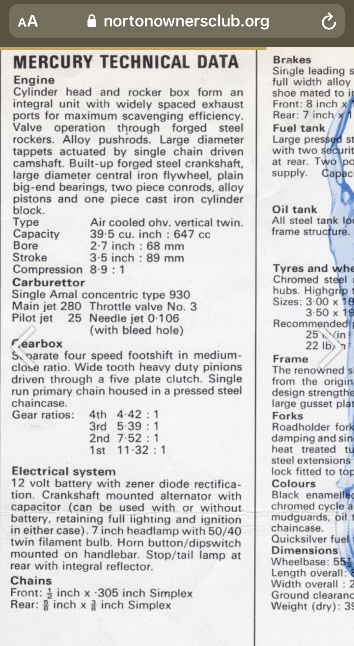
Mercury Carb Data
Philip!
I've been trying for some time to find carb data for the Norton Mercury. There's no info in any of the standard works.
Happened to see your comment regarding the Addendum in manual P106/P.
Could you possibly share this carb info?
Thanks,
/Chris
- Log in to post comments
All good
I have given the Mercury wiring diagram a once over and it is very good. Odd having the fuse in the earth line but otherwise fine. If you are rewiring/rebuilding then you will get a rectifier but NOT a Zener unless you have the original and have had it tested (I can do it). So you will have to remove the Zener and the rectifier, and replace them with a modern regulator/rectifier. Retain the capacitor (2MC type).
- Log in to post comments
Mercury Carb data
Hi Chris
I have attached a screen shot from the Mercury brochure which has the data you want.
If you want to see this yourself luckily it is on the club website in the new brochures section,’page 470
regards
Simon
- Log in to post comments
Advantage with fuse in earth wire
If you intend to remove or fit the battery and don't use the normal practice to first disconnect the earth battery pole, instead you start with the negative pole you might short circuit the battery with a spanner or screwdriver. Then the fuse will blow. No big spark, no damaged battery. On some bikes, the battery is fastened with a metal strap. If the negative (live) battery pole comes in contact with the strap, no problem if the fuse is on the earth side of the battery. Used earth side fuse since I first rewired a Dommie 55 years ago.
- Log in to post comments
Hi Mikael. Interesting that…
Hi Mikael. Interesting that you fit a fuse on the earth side of the battery. Is that in addition to a fuse on the negative side of the battery or instead of the negative side fuse?
Al O, do you have any views on which side of a battery is better for fusing? Or perhaps 2 fuses are better than one?
Regards
Tony
- Log in to post comments
Instead of
Two fails twice as often as one. One is enough. But if you have multiple circuits protected by different fuses as you have in cars and modern motorcycles, having them on the live side (nowadays positive) makes wiring easier and cheaper to manufacture. Of course you can't have the fuse on the earth side on a bike with electric start.
Had a non-starting problem on a Honda CBR600RR last year. Fuel pump not working. Found that in order to start a chain of three fuses, three relays, four switches and a lot of connectors had to be in good order. Spraying CRC 5-56 in the kill button solved it.
- Log in to post comments
I agree with Mikael...
... and fit a fuse in the earth side for the very reasons he mentions. If you have earth wires (like a Commando for example) and short the live terminal out it can melt those wires in the harness causing a horrible mess.
- Log in to post comments


Can anyone tell me what the correct brake light switch should be for a 1969 Mercy and hopefully the oem part number. thanks.