
Wiring recommendations
- Log in to post comments
I used the thin wall on my…
I used the thin wall on my 99 when I re-wired 8 years ago and it's been perfect. I also used some Japanese style bullets - which also have worked perfect.
- Log in to post comments
My reluctance to use more…
My reluctance to use more modern replacements would come down to , does it look right ?, and will it have the same resilience to mechanical wear from movement against components .
- Log in to post comments
Wiring recommendations
Several points to note. The HARNESS as fitted by the manufacturer was a very convenient item. It allowed ALL the wires to be bundled together and a single fit to the machine. Having wired up a few bikes I do 'go for' a loom/harness but connect up the parts as needed. ie pickup wires 'do their own thing' and the alternator wires. Thin wall cable has the same current capacity as the original cable, but within thinner insulation, that can tolerate more heat. Changes to the original set up-the regulator/rectifier will replace the original rectifier (wire for wire). While you won't need the 6V alternator switching wires.
Suggestion-I sell a wiring kit, all the correct cables (some in thin wall if wanted) and the connectors. Except that the original F crimp bullets (4.7mm/3/16) as used on the Commandos are no longer available, ie not as made in the far east. So if wanting to continue with the Snap connectors then we have to use the brass 4.7mm, and either solder or purchase the very expensive crimp tool. (or use the Japanese size) bullets and change to the female connector system.
- Log in to post comments
I've been using the thinwall cable...
... for years - the 1 mm square 16.5 amp does very well for most circuits. It's readily available in all colours from Vehicle Wiring Products although I prefer to use a local supplier in Redditch as their prices are a bit better plus VWP charge a lot for postage especially if it's just a small order.
The only drawback I find is that the insulation seems to melt more easily when soldering if the iron's left on too long. I solder all my connections as I don't have a fancy crimping tool and see no reason to buy one.
- Log in to post comments
Soldering cables
People say that soldered cables are prone to failure from vibration and so are to be avoided on old British bikes and the likes. I'm not sure how much of an issue this really is but if you do buy your thin wall cable from Vehicle Wiring Products they have a great item well hidden in their "Terminals" section under "Heat Shrink Pre-insulated Terminals" called a "Heat shrink/solder butt connector". These are a great way to join cables, especially if you want to join old cables that don't take to solder too easily. I splashed out (no pun intended) and used Superseal waterproof connectors too, where needed, from the same supplier. A lot of peace of mind if you live in a damp soggy place. They're a bit tricky to put together and do require a particular type of crimping tool, but a simple non ratchet one doesn't cost much at all and then you have it for all your other crimping jobs that you're going to have making a new loom.
As far as your actual question goes. Thin wall cable worked well for me but the colours available (from Vehicle Wiring products at least) can't be matched to the original cable system. I don't see this as a problem as long as you make a decent wiring schematic for your new harness. Something that I feel should be the first job anyway, because then constructing the harness is just a question of following your own design..... Much easier.
- Log in to post comments
Hmmm. Better not to forget…
Hmmm. Better not to forget to give it to them then!
- Log in to post comments
It's interesting...
... what you say about VWP not having the correct colours. My local supplier, ALM in Redditch, seems to have the full range: https://www.almsolutions.co.uk/index.php?main_page=product_info&cPath=3_60&products_id=42
- Log in to post comments
Thinwall wiring
ALM a good choice for thinwall wire with excellent product info. I solder all my wires too except where absolutely necessary. Use adhesive heat shrink sleeving over the joints to give a tidy, secure connection.
Never had any soldered wire fractures on bikes ridden all year round over tens of thousands of miles, Plenty of dodgy connectors removed however, British and Japanese.
- Log in to post comments
Thanks for all your input…
Thanks for all your input. It's much appreciated. I'll be using thin wall wires when the time comes.
On the subject of connectors, I won't be using the old style rubber sleeved bullet connectors, I've had too many fail over the 60 years I've been riding. I'm not a stickler for originality. My bikes get ridden, not trailered to shows, so reliability is of prime importance. I will almost certainly use the multi-pin connectors as used on modern bikes. The male and female halves lock together mechanically so they can't separate accidentally and the contacts are gold plated giving a corrosion free and electrically "as good as it gets" connection. I've used them before and have the correct crimping tools. Any thoughts on that?
- Log in to post comments
Battery choice
Looking at the circuit diagram in the Haynes manual, it shows two 6v batteries in series. Was that because back in the day, there wasn't a 12v battery that would fit inside the toolbox? I would like to use a single 12 volt battery if possible and utilise the original battery clamping system and location. Can anyone recommend a suitable battery, please?
Thanks
- Log in to post comments
Multipin connectors
Hi John,
As a fellow non originality stickler, I say go for it. Even better if you get the waterproof ones. I did this on every loom I've made and its so relaxing to know that everything just works. Why not add a brake light switch to the front brake while you are doing the loom as well. Much safer.
As for the thin wall insulation wires, again it is good stuff, but you might need to upgrade your wire strippers as it can be quite tough to strip back compared to the PVC wires.
Regards,
George
- Log in to post comments
You can search Tayna by battery dimensions,
So you can measure the space and get one to fit. Select search and the dimensions boxes appear as if by magic.
It’s a good idea to buy the largest capacity you can for the physical size - less chance of overcharging and; in my experience, likely to last longer especially with an Optimate type smart charger. AGM is the way to go IMO.
- Log in to post comments
I have just fitted a large…
I have just fitted a large Yuasa 12N7-4B acid battery to my 63 SS and discarded the retaining bracket that posed too much of a shorting issue with close proximity to the terminals. Battery restrained by shaped sections of pipe lagging and repurposed rubber mouse mat behind and under battery . Battery box drilled and fitted with acid vent pipe to below silencer. Dont think anything bigger will go in. AGM probably a better bet , but less possibility of reserection if it dies through neglect !.
- Log in to post comments
A Strip of Inner Tube….
…lining the restraining bar on the U bracket (both extended to accommodate larger AGM battery) on Doris keeps the bar away from the terminals.
- Log in to post comments
Wiring circuit diagram
I've bought the thin wall cables that I need and I've spent an hour or two creating a circuit diagram that can be kept with the bike.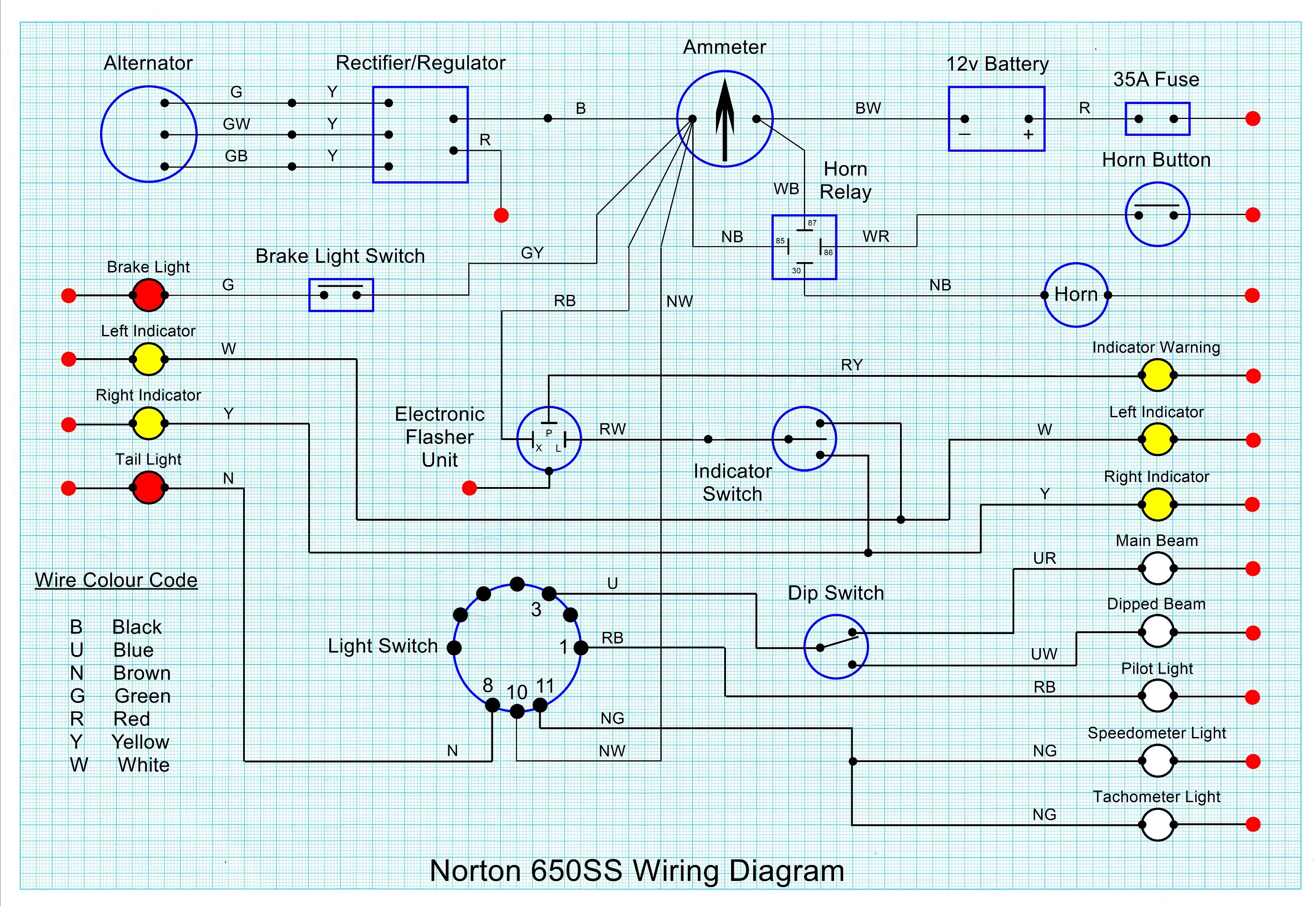
- Log in to post comments
Poor diagram!
The colour code quoted is the Lucas/Rists one, but the wiring on the diagram DOES NOT follow the Lucas/Rists system. There is far too many 'wrong coloured wires'. There is no need for a horn relay unless you have a very high current horn ie air horns. One side of the Ammeter has 5 wires, they need to be ALL the same colour BRN/BLU. The reg/rect is usually 2 wire input, the 3 wire alternator is made into two wires. The early 650ss were 6V (this is a 12V) There is no ignition as it is magneto, so an ignition circuit with ignition key might be worthwhile considering.
- Log in to post comments
Poor Diagram !
Hmmm...ok, Mr Osborn. My bike isn't intended to be a 100 point restoration. It's being built to ride in todays road conditions so it has indicators. They were never fitted originally so there is no provision for them in original wiring. As I'm doing the wiring and making the harness, I will decide what colours I use. I see no reason at all why I should use the same colour for all the wires on the ammeter. That will just lead to unnecessary confusion at some point down the line. I chose to use a horn relay to reduce the current being switched by the horn button in an attempt to improve reliability. The Mosfet rectifier/regulator I've fitted has a 3 wire input because the alternator has a 3 wire output... one for each of it's 3 phases. And yes... a key switch in the magneto kill lead is probably the best I can do.
Having said all that... thank you for your observations. I will take note, but probably ignore them.
- Log in to post comments
Roadholder Offering
John.....that is a very tidy circuit drawing. It is easy understand and incoporates most of the sensible modifications that a DIY builder would add to his Norton.
Can I suggest that you offer it for publication in Roadholder?
Possibly add that the Light Switch is a Lucas 88SA item.
- Log in to post comments
Can you explain as to why…
Can you explain as to why you have the 35amp fuse situated in the earth run from the battery.
- Log in to post comments
Fuse location
Yep...
Electrically, it doesn't matter which lead the fuse is in. The fuse is there to protect the wiring in the event that the current being drawn exceeds the rating of the fuse... If a short circuit occurs, for instance. In that case, the current being carried by the battery leads will be the same in both.
In my case, it was just more convenient to put the fuse in the positive battery lead.
- Log in to post comments
Fuse in....
A reasonable good answer John. But there is a few other considerations, The original fuse as fitted in the Lucas wiring on all British bikes is/was a white nylon plastic (bayonet fit) No longer available. Looking like a suitable replacement we have a white nylon bayonet fit with a RED wire. The wire is crimped to the fuse connector-poor item. If you use it as a traditional fuse on a Norton you end up with two RED wires on the battery-disaster. Continuing with the fuse issue, I have been supplying a 'screw' together item for 30mm glass fuses, but now I will be supplying a Blade fuse and holder. (the cables can be the right colour and in the live side or in the Earth if you wish)
DO NOT publish this diagram! Most of the wiring colours are wrong. I am happy to correct them for publication.
- Log in to post comments
Alan... You're correct, you…
Alan... You're correct, you don't want a red wire connected to the negative side of the battery. You're also correct about the white plastic bayonet fuse holders, they all seem to have red wires of questionable current carrying capacity. I certainly wouldn't advocate using one of them on the negative side, or for that matter on the positive side. I have some blade fuse holders with moulded in red wire of a suitable current carrying capacity, which is the main reason I will use it on the positive side. It's not shown exactly on my diagram, but I always use a red ground return wire to all elements. It wasn't Joe Lucas's fault that the electrics failed so regularly on our old bikes, it was the daft manufacturers using the frame and tin-ware as part of the circuit. Paint is a reasonable insulator, as is rust.
- Log in to post comments
Most if not all of the bikes…
Most if not all of the bikes that I have /owned have been form AMC with the red leads being positive earth and the fuse in the negative live side of the harness as per their respective hand books.
I just wanted to know if there was any extra benefit for having the fuse in the positive earth circuit.
Having said all that, if it works for you and all is well carry on restoring your SS.
- Log in to post comments
A master fuse in a sole…
A master fuse in a sole return wire, near to the battery, protects the wiring against the short circuit that happens when a screwdriver or spanner connects the battery live terminal to the frame, or the battery box contacts the live terminal.
This does not apply to electric start bikes.
- Log in to post comments
I use one of those blade…
I use one of those blade fuses in the return lead on my negative earth Triton.
I disguised the red wires with black heat shrink tubing.
- Log in to post comments
Then the black heat shrink falls off....
And then some one adds an Earth wire direct to the battery-this completely negates the fuse! Another clever trick in this area is several wires on one terminal of indeterminate colour-remove battery for charging, months later replace battery-BUT I have a spare wire! At this point we have stupidity, and expensive smoke. Standard colour scheme is another good starting and finishing point.
- Log in to post comments
BSM
Personally I prefer the Battery Status Monitor (that Alan sells) instead of the ammeter. A quick glance tells you all you need to know. Have had too many useless ammeters.
Living in a country where correct colour coded wires are unobtainable and importing from the UK nowadays is difficult, I have to fit numbers to the wires.
One thing I like to add is a charging connector. Not really necessary on most Nortons, but e.g.for the Venom where I have to remove the carburettor to charge the battery.
Never experienced a heat shrink tube falling off.
- Log in to post comments
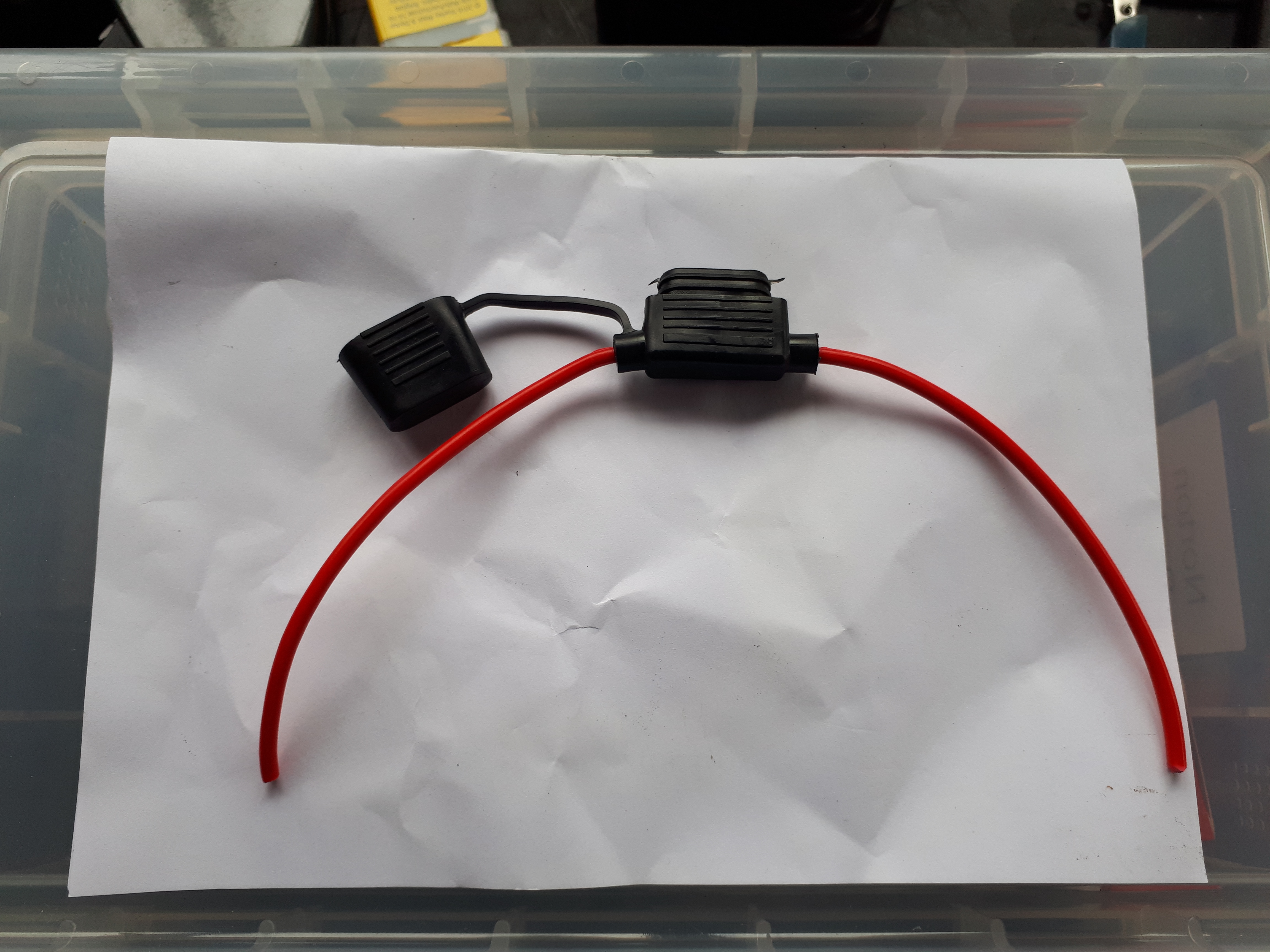
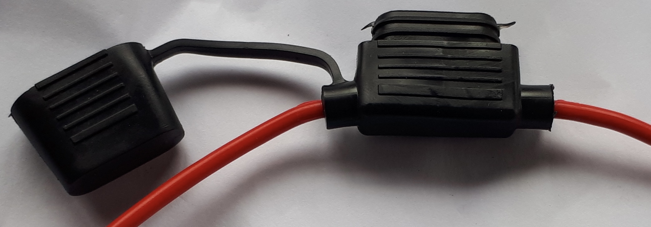
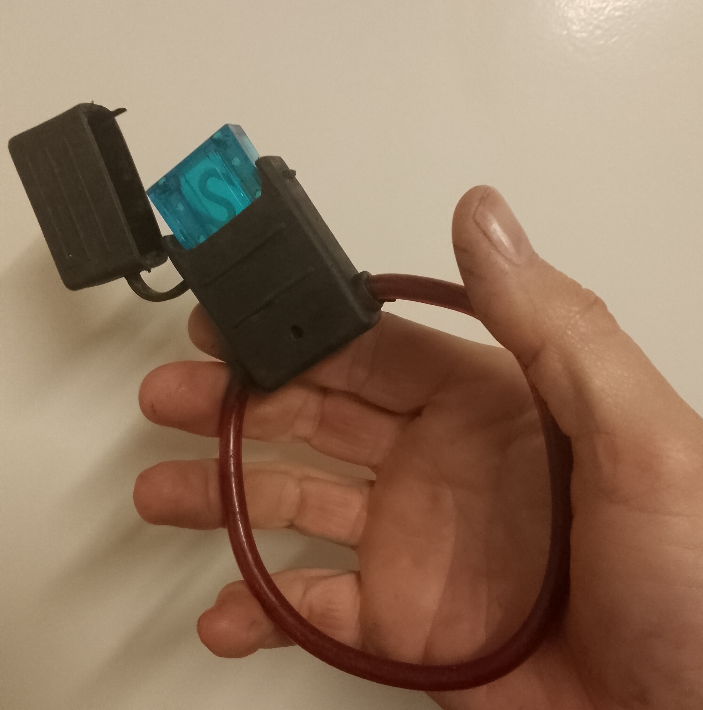
on a lighter note getting…
on a lighter note
getting in from the pub after one or two beers .i thought i know, i will order an inline fuse holder to finnish my wiring to make it safer. well a couple of days later the fuse holder arrived. as you can tell by the photo attached, i over did it a little :)
barry
- Log in to post comments
Hello Barry. …
Hello Barry.
Please allow me a moment of levity if you will by my observation below.
Ale has a high water content. Electrics and water are a bad combination, in your case you have proved this concept.
Ironically if you were to take your tipple with a little added water I think you would fair better with your purchases in the future.
Sermon over!!!
Rgds.
Paul..
- Log in to post comments
That is better than the…
That is better than the glass tube type. Weather and vibration reisistant.

- Log in to post comments
Please do ignore..
Please do ignore my observations. My observations are for others who might be wanting to copy your diagram, bear in mind Phil H thought your diag was good!
Indicators became standard colour scheme in the mid 60s so the colour is there. All British Vehicles had/have the same colour scheme. Your alternator (if standard) is NOT 3 phase. No Norton motorcycle prior to the modern ones ever had a 3 phase as standard. I have never known a traditional horn button become unreliable. Confusion? Having 5 wires at the same point with the same potential ie unswitched battery all different colours?
If anyone wants to rewire such a bike, crib the colours off of a /Mercury/early Commando or get in touch, or look up the Lucas/Rists colour scheme for ALL British Vehicles.
Reg/rect using current when off, yes a point to note, but if this is a problem then it should be noted with the reg/rect. In a lot of cases the reg/rect is intended for a coil ignition bike, so there is a wire to the ignition side of the ignition switch-(takes care of this function).
- Log in to post comments
"Your alternator (if…
"Your alternator (if standard) is NOT 3 phase. No Norton motorcycle prior to the modern ones ever had a 3 phase as standard. I have never known a traditional horn button become unreliable."
My bike does have a 3 phase alternator. There wasn't an alternator among the boxes of bits I started with so I had to buy one anyway. It made sense to fit a 3 phase version as they give a better output at low revs. I've used them on both my Meriden Triumphs without any issues. The Mosfet regulator doesn't draw any current when not in use, but it doesn't really matter to me anyway as my bikes are plugged into a maintenance charger when in the garage.
Because I've fitted indicators and therefore needed an indicator switch, I've bought a "left hand cluster" which comprises a dip switch, an indicator switch and a horn button. I chose to fit a horn relay as I was unsure how well the horn button in the cluster would cope. It's easier to fit one now than to have to modify the wiring harness to fit one later if needed.
- Log in to post comments


I have to start thinking about making a wiring harness for the '63 650SS that I'm restoring. Purchasing a standard harness isn't really an option as the machine will have indicators and a solid state rectifier/regulator unit which weren't on the original bike. Building the harness isn't a problem, I've done it many times before for various bikes but I've always used the older PVC insulated cables. This time, I'm thinking about using smaller overall diameter 'thin wall' insulated cable (with the same current rating).
Is there any reason why not?
John