
Hello, I recently bought a 750 Commando, VIN plate says Oct 1972, all stamped numbers match.
Just wonder if anyone knows what the items shown are for? It's been imported form the USA if that helps.
Thanks Ian, the numbers look…
Thanks Ian, the numbers look the same to me, even the gearbox. Unless there's been some fiddling but I can't see any witness marks and the VIN plate rivets look authentic.
- Log in to post comments
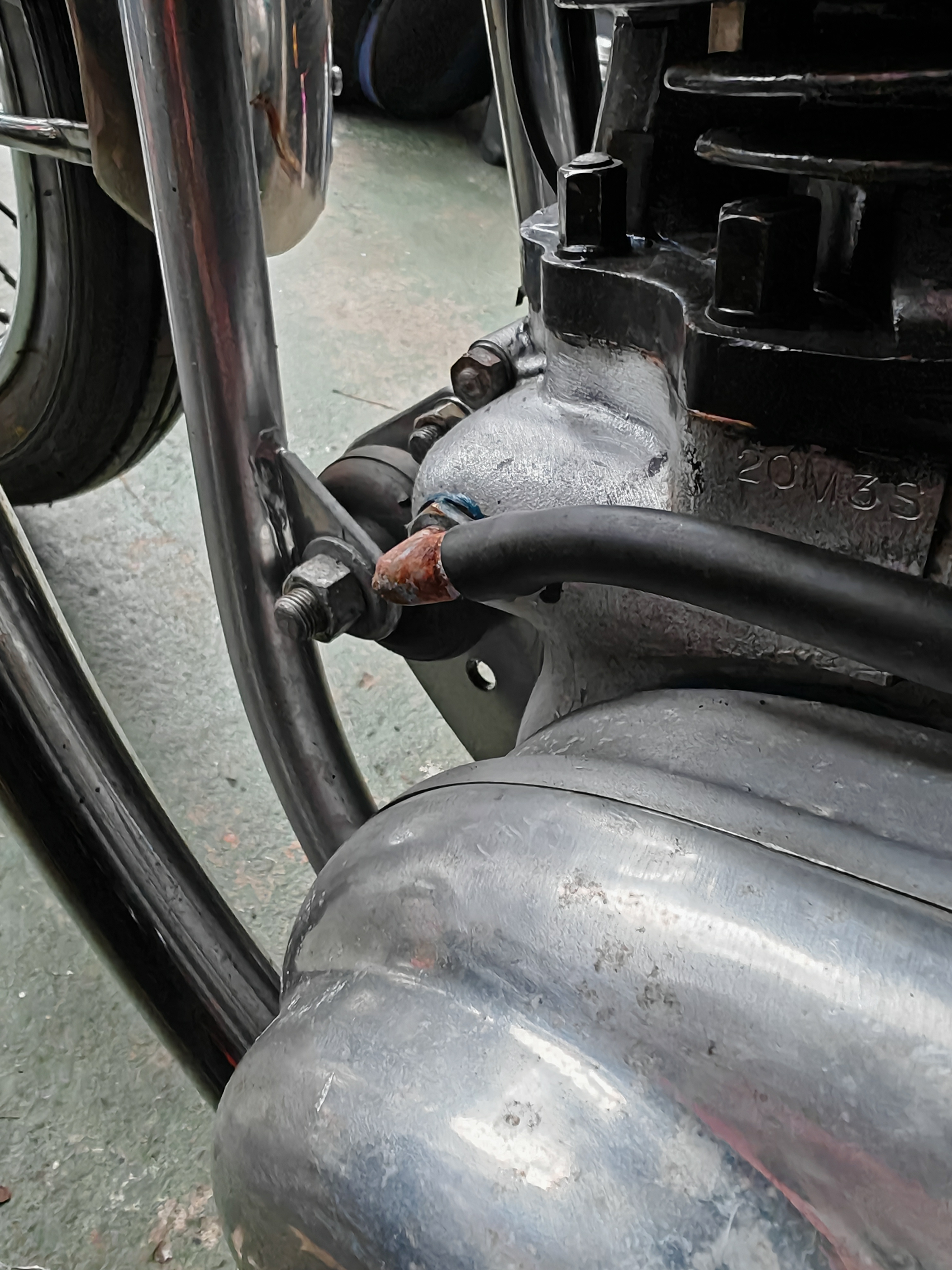
2 Breathers?
This engine appear to have 2 breathers. The Atlas type on the end of the cam shaft should need to be removed when the one at the back of the timing case is fitted. When you remove the Atlas one you are left with a fine threaded hole. A good 'bung' for this is the clutch adjustment screw.
- Log in to post comments
Thanks Alan, the front…
Thanks Alan, the front breather looks a bit home made, an elbow fitting with a lock nut to position it. I'll find a way to plug it if it has potential to cause engine damage. 7
- Log in to post comments
The front is NOT...
The front breather is NOT home made, it is standard ATLAS as fitted to the first Commandos up to a specific engine number. There is no engine damage with extra breathers but what will happen I do not know.
- Log in to post comments
Thanks again Alan, maybe…
Thanks again Alan, maybe someone decided to add an Atlas breather later if it's beyond the change of design date.
- Log in to post comments
Thanks Gordon, it has a…
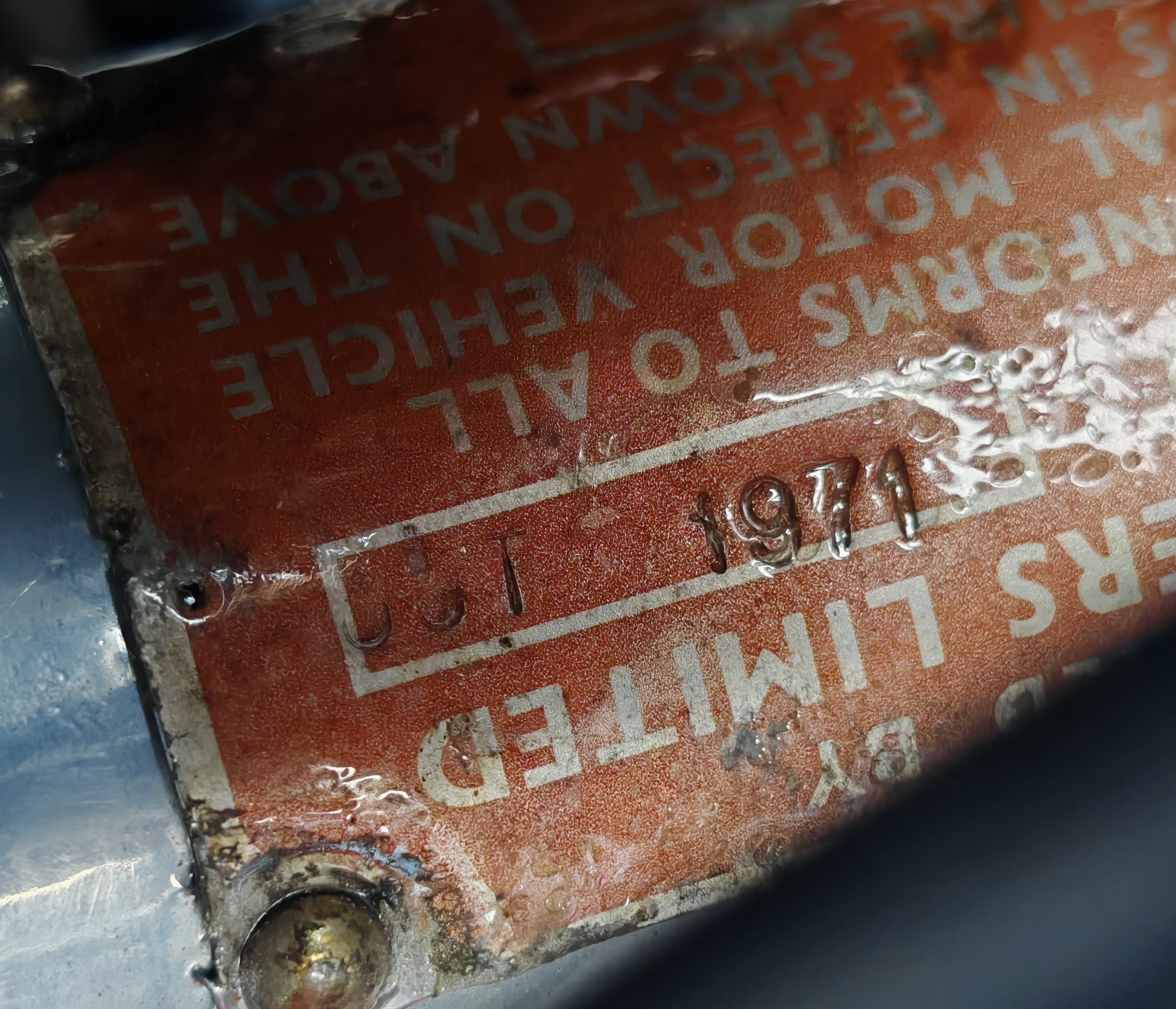
Thanks Gordon, it has a layer of protective plastic over which has lifted and moved a touch making the numbers looked a bit smudged if that's what you mean.
- Log in to post comments
It’s possible there has been…
It’s possible there has been an attempt to remove the data plate for painting/powder coating the frame. Not done too neatly, but new plates and rivets are available from Andover Norton. Looking at the Greg Marsh site relating to Commando numbers: https://www.gregmarsh.com/MC/Norton/Info/CommandoID.aspx Engine number 20M3S 150658 would have been manufactured in 1971. Quite possibly left the factory and been registered after that. NOC or Andover might have the records. It would have had the camshaft end breather, and a blank plate where your second (additional) breather has been fitted. (From engine number 200000, the breather was moved from the camshaft end to between gearbox plates behind engine.) The Commando survey on the same site lists a bike with engine number 150651, 7 away from yours, as having a label date of Sept 1971, and is a 750 Fastback, Registered in 72.
- Log in to post comments
Thanks very much Douglas for…
Thanks very much Douglas for sharing your knowledge about the VIN numbers. I must also apologise to all for any confusion as I misread the date on the VIN plate, it is Oct 1971 which ties up with the information from Douglas.
- Log in to post comments
The breather....
The breather behind the timing cover has been added, its position I understand is adequate.
The Atlas one is factory original.
- Log in to post comments
The breather on the back of…
The breather on the back of the timing case looks well done and, at a guess, incorporates a positive crankcase ventilation valve (PCV). You can search on here for discussions of PCVs on Commandos. The breather at end of the camshaft is timed which is supposed to have the same effect as a PCV (but doesn't).
As the Commando evolved, the breather moved around until it finally ended up on the back of the timing case, i.e. where yours is fitted. If it were me, I'd blank off the one on the end of the camshaft and rely on the one in the timing case.
- Log in to post comments
Thanks Stan, I'll have a…
Thanks Stan, I'll have a look at the PCV posts. I'll dismantle the item and inspect. I'd like to do away with the camshaft breather if only for aesthetics, too many pipes looking like the back of a washing machine. Which reminds me I need to fit a little tap to the hose that oils the chain.
- Log in to post comments
The chain oiler only every…
The chain oiler only every oiled the back tyre. Best removed and blanked off. Modern chain lubes are pretty good and come in a handy spray can - no more taking the chain off and boiling in Linklyfe.
- Log in to post comments
Thanks, here's me thinking…
Thanks, here's me thinking it was a good idea. I better block it.
- Log in to post comments
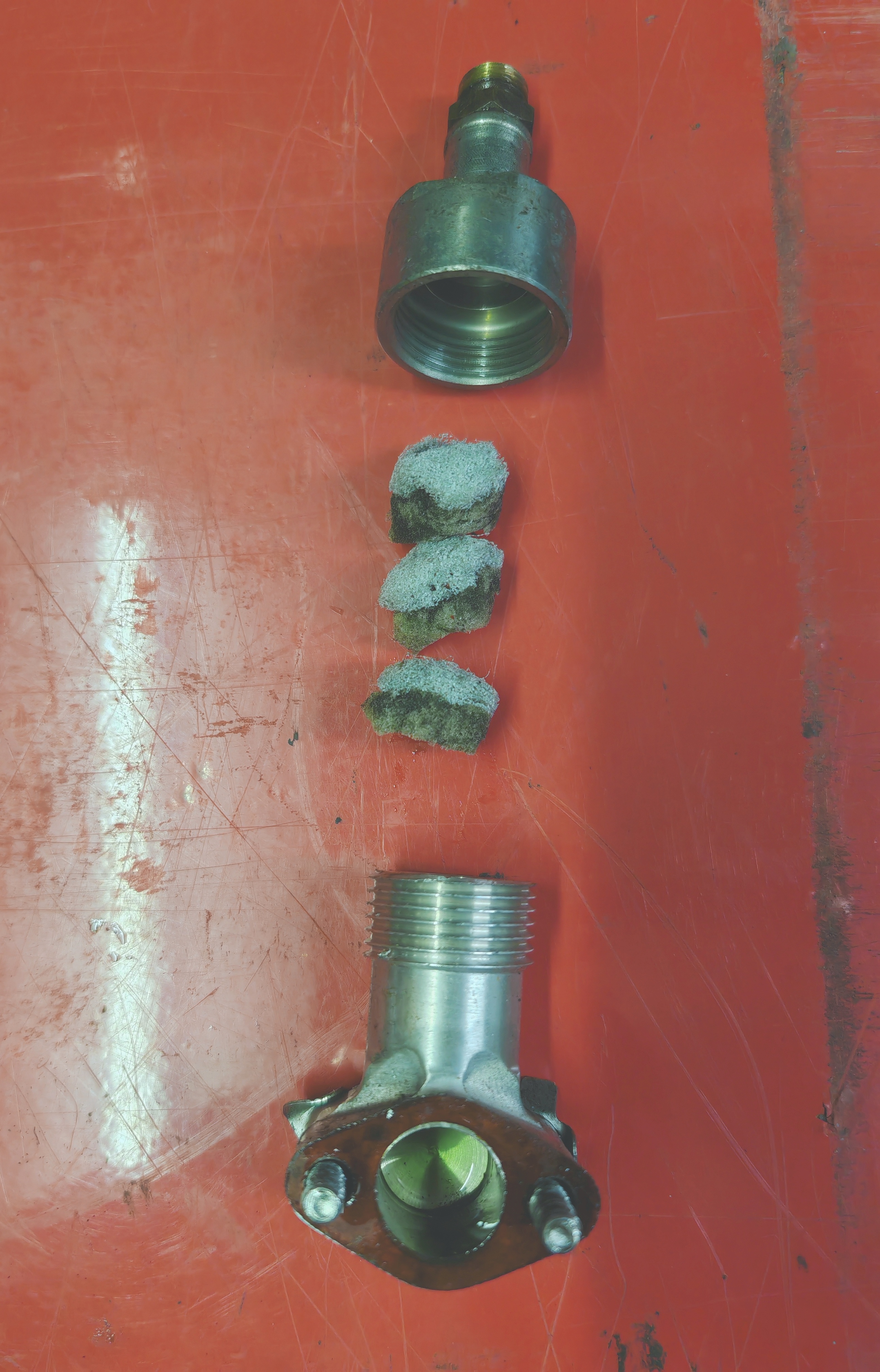
Update. It's nothing more…
Update. It's nothing more than a glorified elbow joint stuffed with bits of sink sponge covering a 3/8" hole. When I blow through it it's got a bit resistance but I don't know how much pressure or vacuum is caused by crankcase breathing. I'll see how it goes and can always fill it with copper wool if less resistance is beneficial?
- Log in to post comments
Looks like your additional…
Looks like your additional breather uses the parts which Norton used when the breather moved to the back of the crankcase.
This page from AN shows the component parts, including the sponge/foam:
- Log in to post comments
Thanks Douglas for your…
Thanks Douglas for your great information. It's the same but different to the one you've shown, I've got some reticulated foam to try, the same as shown on their site. I also note it's laid over 90° to how mine is. I'll do the same with mine because sticking up like a sore thumb messes with my feng shooee
- Log in to post comments
That's disappointing. I was…
That's disappointing. I was expecting at least a flapper valve in there. I'd throw the bits of sponge away and leave it open like the late 850s.
Wouldn't take much to adapt what you have to incorporate a valve.
These BMW reed valves https://www.motorworks.co.uk/crankcase-breather-valve-ena35712-2.html are popular with some people. 1.25"(!) diameter x 0.5" overall height
- Log in to post comments
Thanks Stan, I'm in the…
Thanks Stan, I'm in the process of tipping it over 90° to make it less unsightly and will replace the soggy sponge with reticulated foam. I'm also pondering having a housing made for that clack valve you've shown.
- Log in to post comments
Thanks Gary, I've got the…
Thanks Gary, I've got the timing side cover off at present ready to change the worn cam chain, I'll have a look and provide a hole if need be.
- Log in to post comments
I checked Gary and there's…
I checked Gary and there's some holes and would it also not breathe through the main bearing?
- Log in to post comments
Breather
I don't think the first hole can breath. I did not have one above the timing chain, as you do, so that will probably do.
I bought mine with the breather in the same place as yours, being a popular mod at the time. Head gasket kept leaking & couldn't seem to cure it. Changed it a few times until I found the problem of over pressurising. Put the breather back to the back of the crank case & all was good. Only thing is, that is when it has wet sumped, it would push all the oil up through the breather.
- Log in to post comments
A BSA I had would do that…
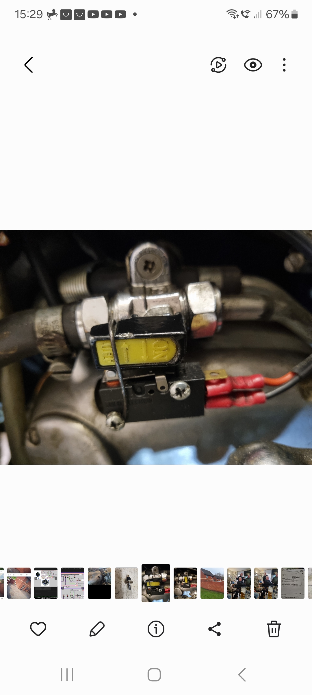
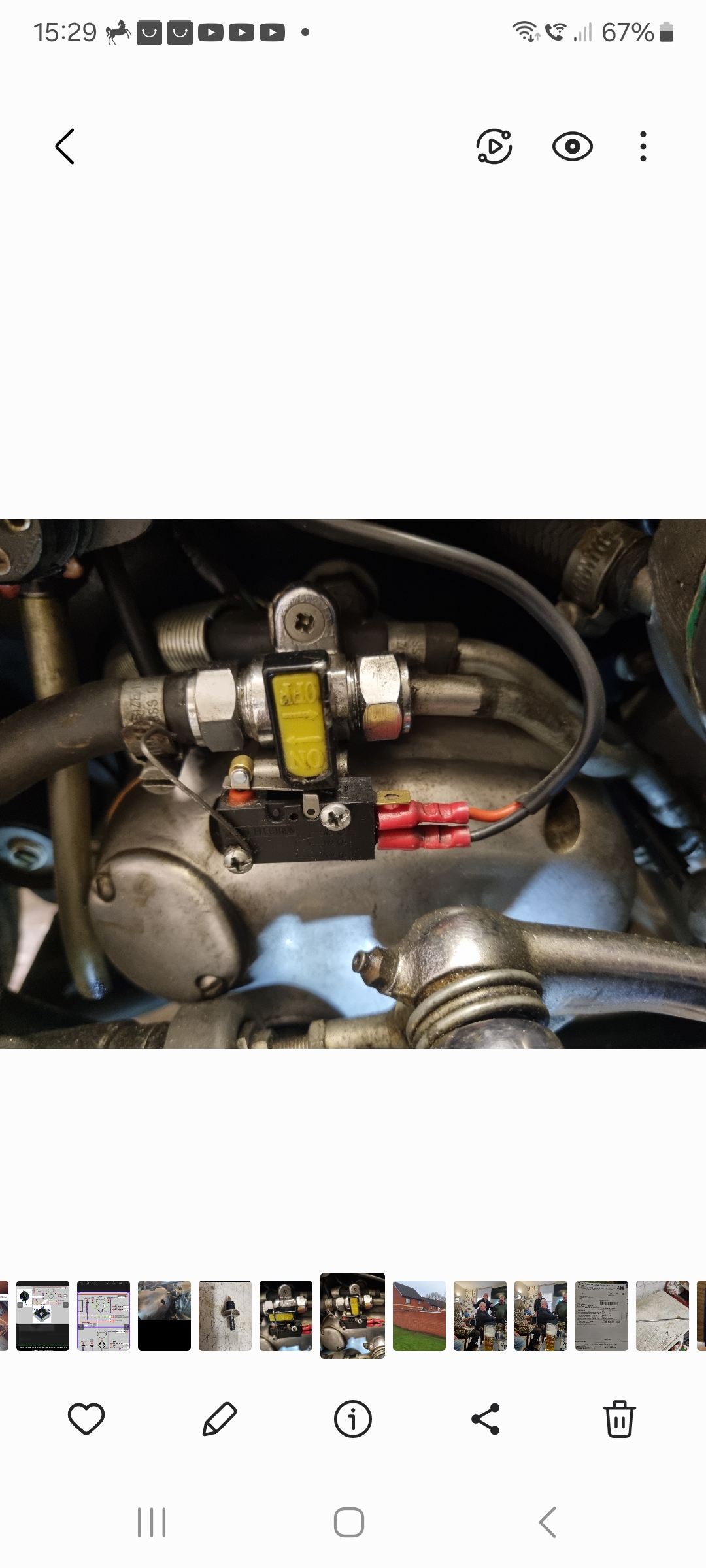
A BSA I had would do that too if left too long.
This bike has a tap on the oil feed line which I'm not keen on. My plan is to either remove it or tether the ignition key to it, with the tether just long enough to reach the switch with the tap lever turned on or find a tap with ignition circuit cut out, I saw these advertised but sold out.
- Log in to post comments
Oil tap
Hi Adam, not sure what oil tap you used but I fitted a cheap Gas tap with 10mm compression joints either side, it was foot mounted type so I could make a bracket to fit a heavy duty 10 amp micro switch which connects to the harness just before the ballast resistor to cut the ignition off works quite well.
Also fitted a spring clip to keep it open when running.
Graham
- Log in to post comments
71 cases breather set up
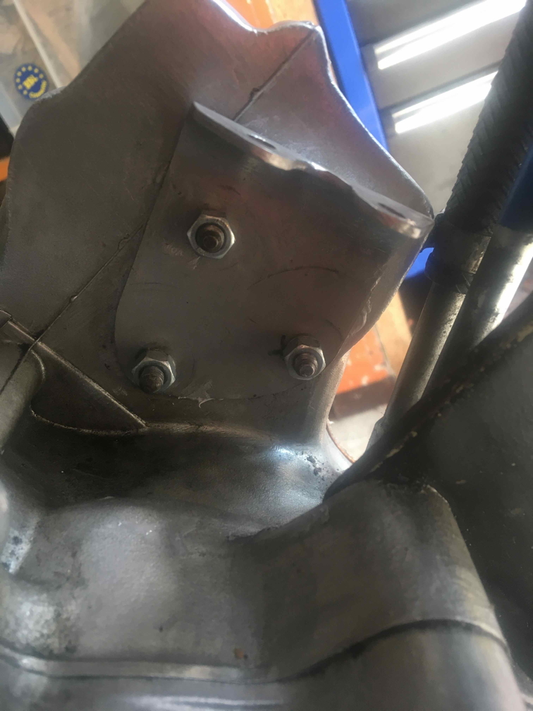
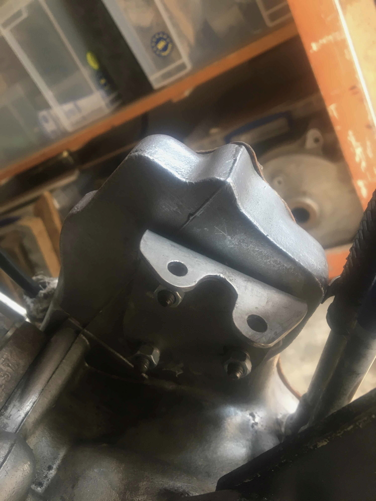
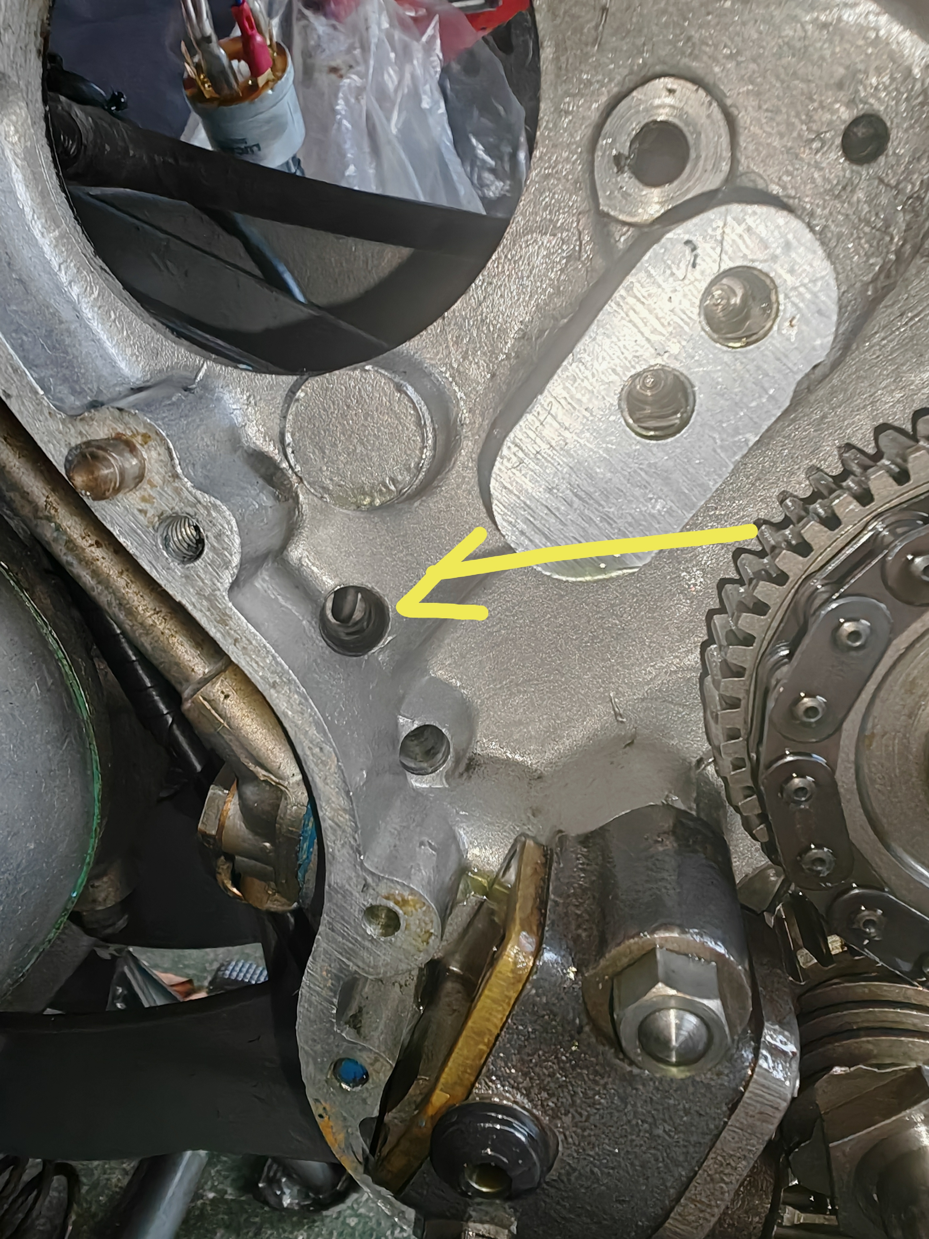
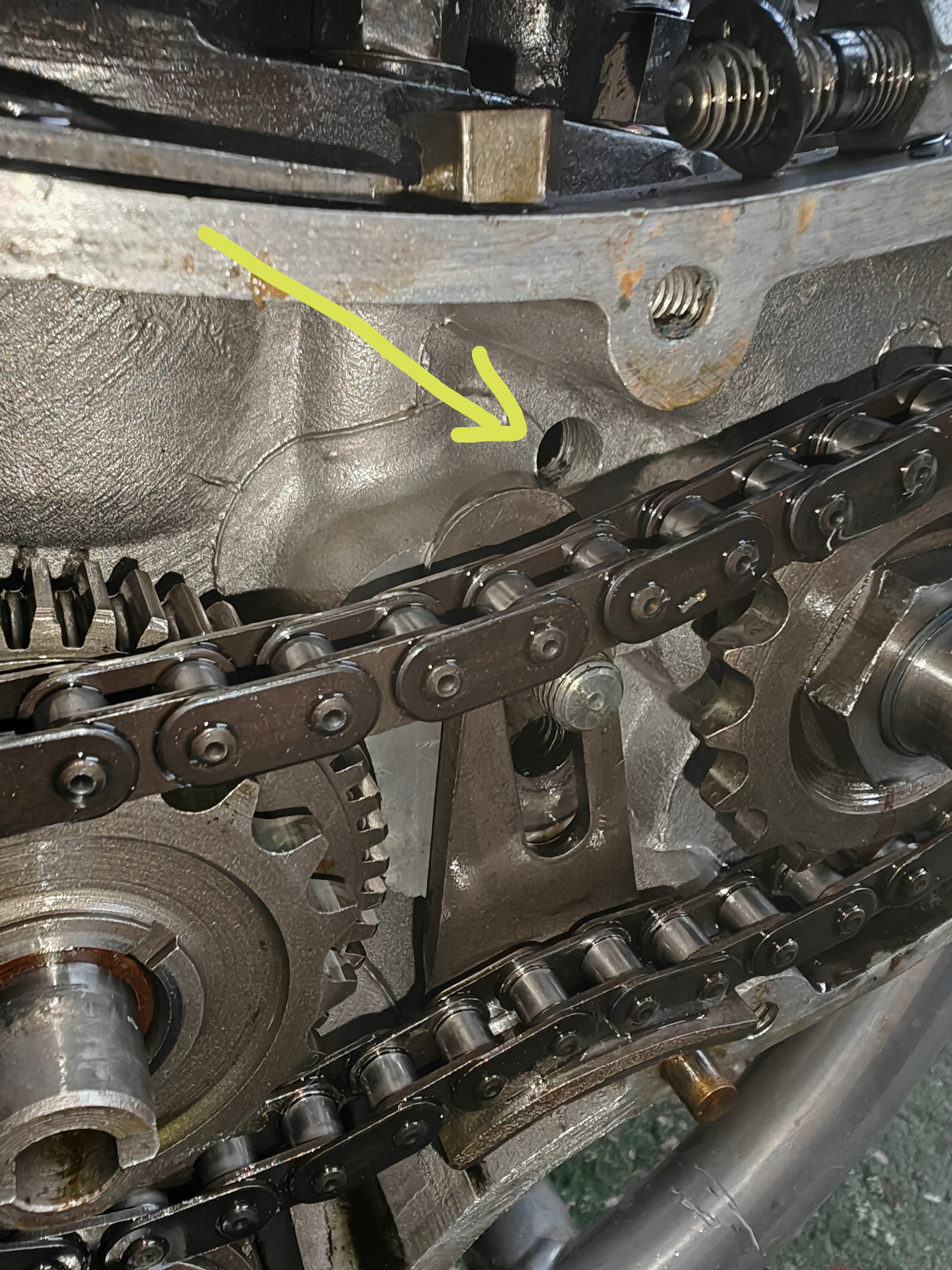
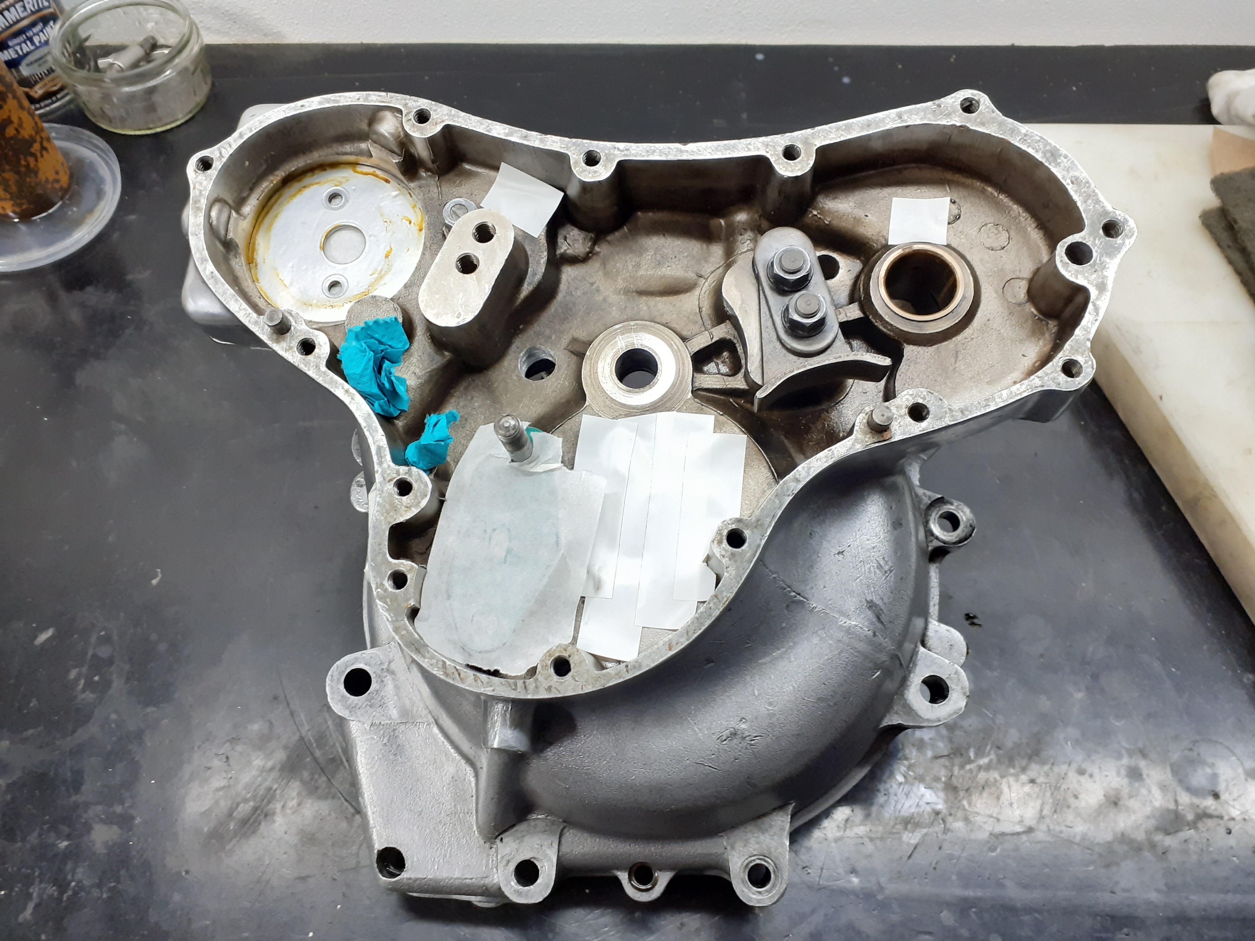
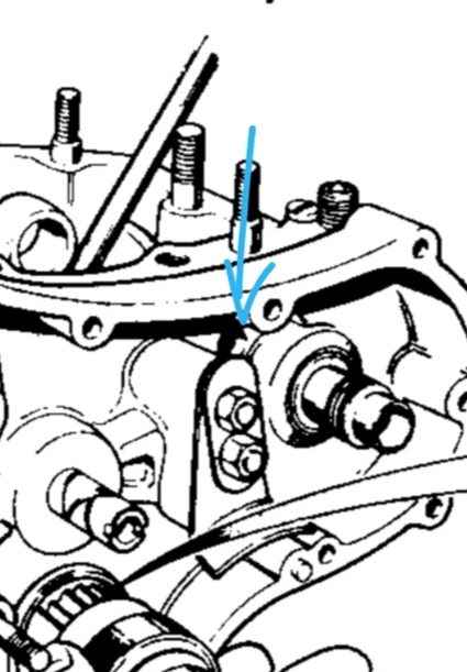
There's a mountain of information about this subject, but that's the problem. Most of the information doesn't quite apply to you if you have the cases with the timed disk breather on the end of the cam. So having been through this mountain myself maybe I can save you the time. Adding another breather is popular because the general concensus is that the one on the end of the cam can't quite cope. It's important to decide if your adding another one or replacing the original cam end one. As long as the timed disc set up still exists on the end of the cam and still works then it's best to keep it in addition to the new one on the timing side. Sometimes owners replace the cam (which fail often) with one which does not have the machined end to accommodate the timed disc set up, so although it appears to be the standard set up, there's actually no disc in there. You need the disc and you need to know if it's there or not. If it is there then this is good. However, as Gary pointed out, plonking another breather on the timing side isn't enough and although you do have one orifice into the crankshaft chamber (compared to later cases which do not have this one), this isn't enough. You need to add some/one, otherwise the added breather, which has opened the timing case to the athmosphere, can allow oil to flood into the timing chest and sometimes even up and out of the breather. Before it was added this can't happen as the timing case is closed and thus slightly pressurised. Also, of course, you need the added air flow passage. There are many drawings showing you where to drill the hole(s), which size and how many. Andover Norton offer one (attached) for the combat, but the combat cases are different from yours. Jim Comstocks' website will find you a design, but it is intended for a racing engine and the cases are peppered with 12mm holes, as is the very clear example on the Mick Hemmings engine rebuild DVD. However, if you calculate the surface area of both of your breather pipes added together and calculate the area of the gaps in the timed breather discs and add that to the surface area of the hole you already have in the timing case near the cam (the other hole you arrowed is an oilway) then it's only really an advantage to add one more 12mm hole to get the maximum breathing advantage. I've attached photos of mine where you can see the added hole (sorry cant do arrows just now). There are options for the placement, but it must be well above any possible oil level. Once this is all done you will need to install an efficient positive crankcase ventilation valve on the new breather pipe to get the very best out of it. Hope this makes sence and helps. Sorry if its a bit long winded.
- Log in to post comments
Thanks very much for your…
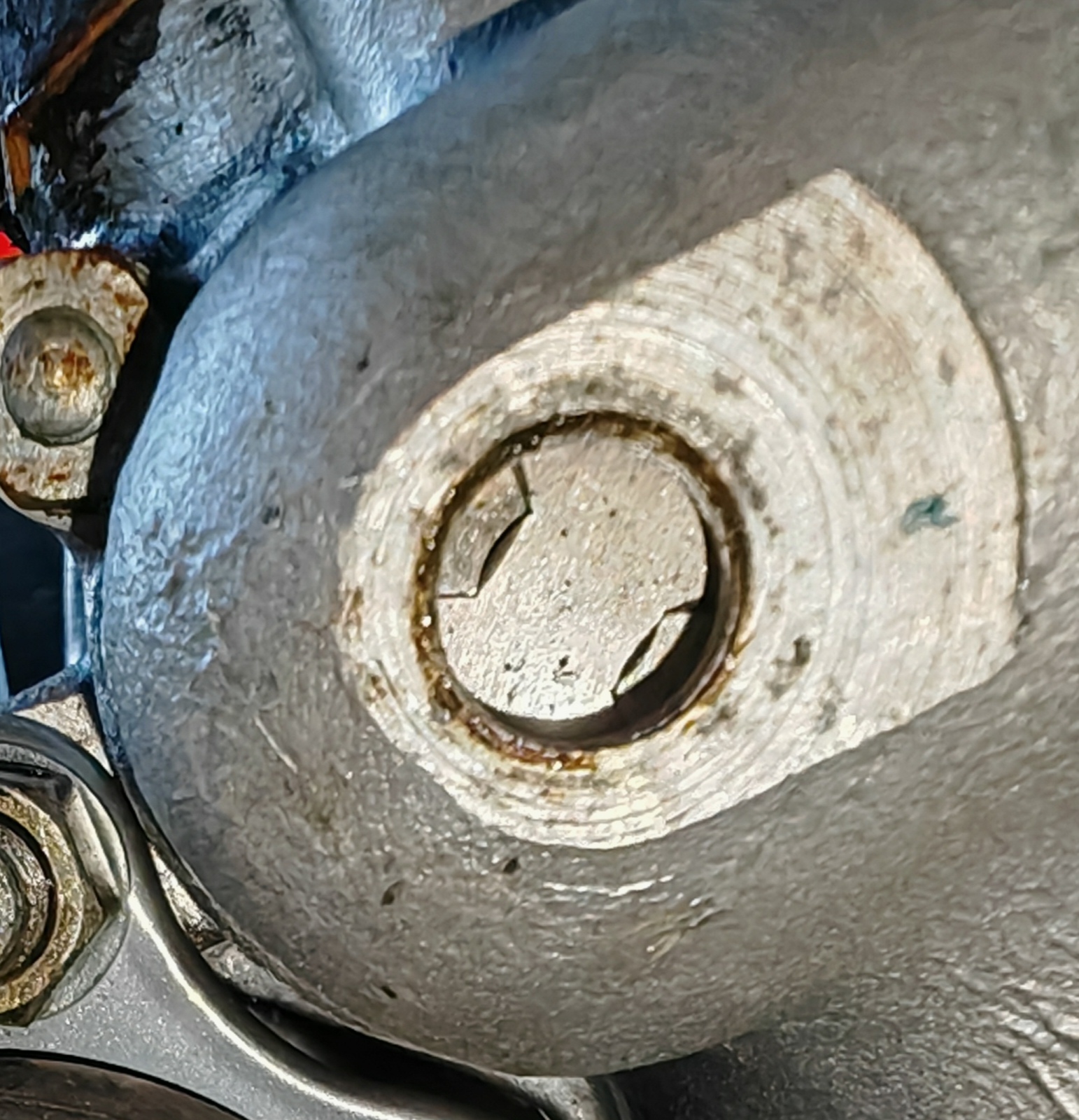
Thanks very much for the time you've spent Graham explaining about the modifications. I must admit I was cross-eyed and frazzled when reading the posts in the technical section on here. I have checked the cam timed breather as shown here. When I turn the crank the windows open so it looks to be complete?
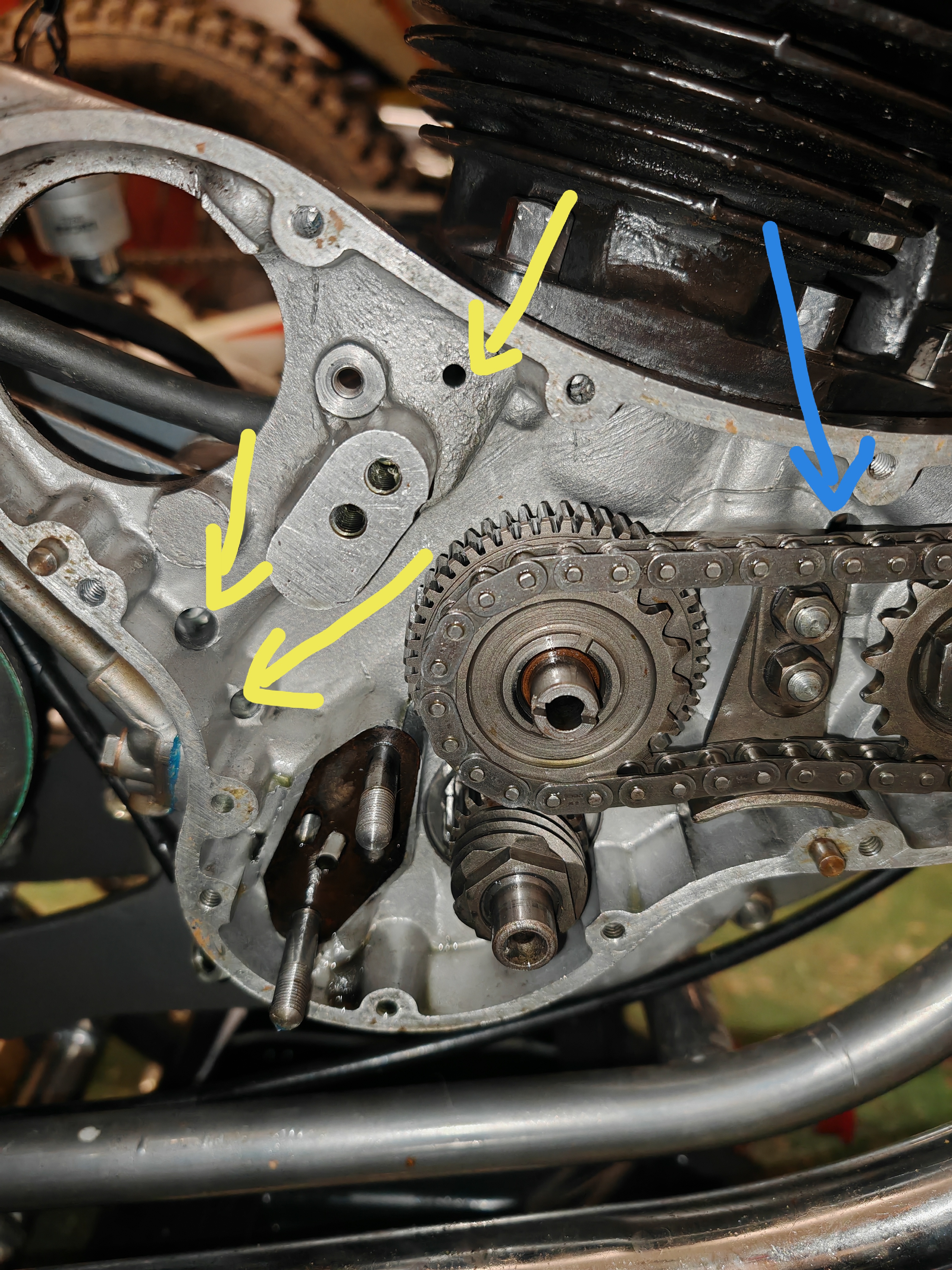
So if I have understood you correctly, this should be OK to run with the additional timing case breather in conjunction with the extra drilling through the crankcase near the camshaft. I understand what you say about flooding the timing chest and wonder if I need to drill another small hole near the oil pump as shown on the drawings you supplied.
I've pointed out other drilling or oil ways in yellow, the blue one is the additional one behind the camshaft. Are all the yellow ones standard?
Just saw in the 1970 onwards manual that there is a hole behind the camshaft the same as mine (shown).
- Log in to post comments
Add one more hole
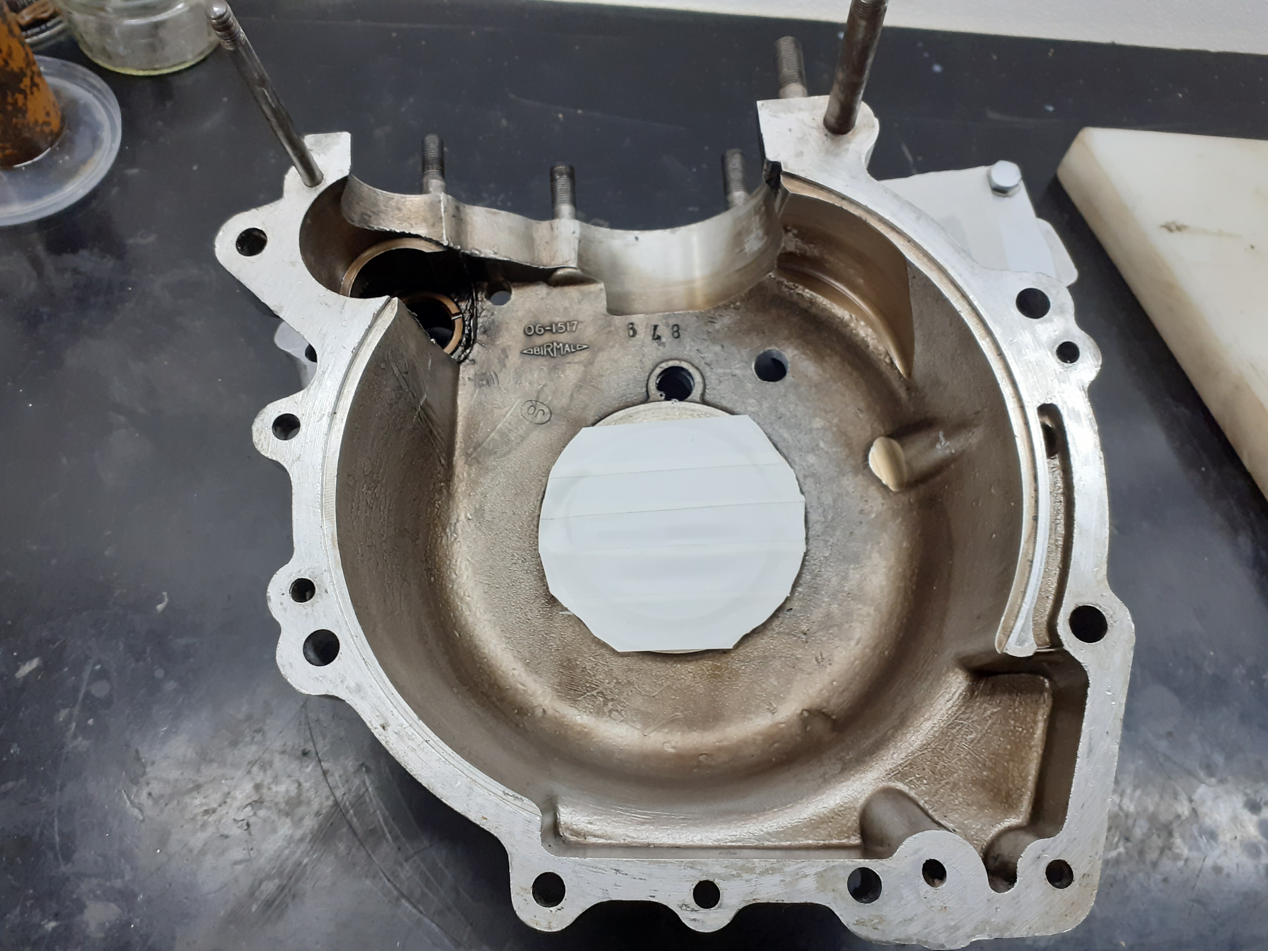
Ahh a bit of confusion may have arisen here. The 70/71 cases do have an extra hole near the camshaft compared to the later cases, but that's not the extra hole I meant. You need to drill another hole in a similar place to the one I drilled, which you can see in the photo I attached. This will give you the sufficient air flow from the crank side into the timing chest for normal road use. As mentioned the racers add two or three more holes but for road use it calculates that one more is enough. This will also prevent the air pressure in the crank side forcing oil into the timing chest, so you won't need to drill an extra oil passage to help it drain back (in my opinion).
The discussion about where to place the PCV is important and also opens a debate about where the end of the added pipe is going to. The racers tend to have the pipe open to the atmosphere, or at the most, fed into an open topped can or bottle just to catch any oil mist that comes out, so they get maximum advantage out of the added holes and increased ventilation as there are no restrictions to the airflow in the pipeline. If you tee the added pipe into the existing pipe, or tee it into the oil tank connection, then it is debatable if you gain anything at all from the extra breather as the diameter of the oil tank connection is restricting the airflow back down to what it was with a single breather pipe. If you have the early central oil tank, the air from the crankcase breather pipes enters the oil tank and then there is a breather pipe for the tank to stop the tank from being pressurised, which would also need to be increased in diameter to get any benefit from the additional breather.....and so it goes on! (The physics of this is that a pipe only has the flow rate of the smallest diameter restriction that there is in the pipe. So if you had a 10 meter 25mm pipe with a 10cm section of 10mm pipe in it, then the whole pipe has the effective flow of a 10mm pipe. So doubling up on the breather pipes, which effectively doubles the diameter of the pipe, has to follow through all the way along the line until the air blows out to the athmosphere).
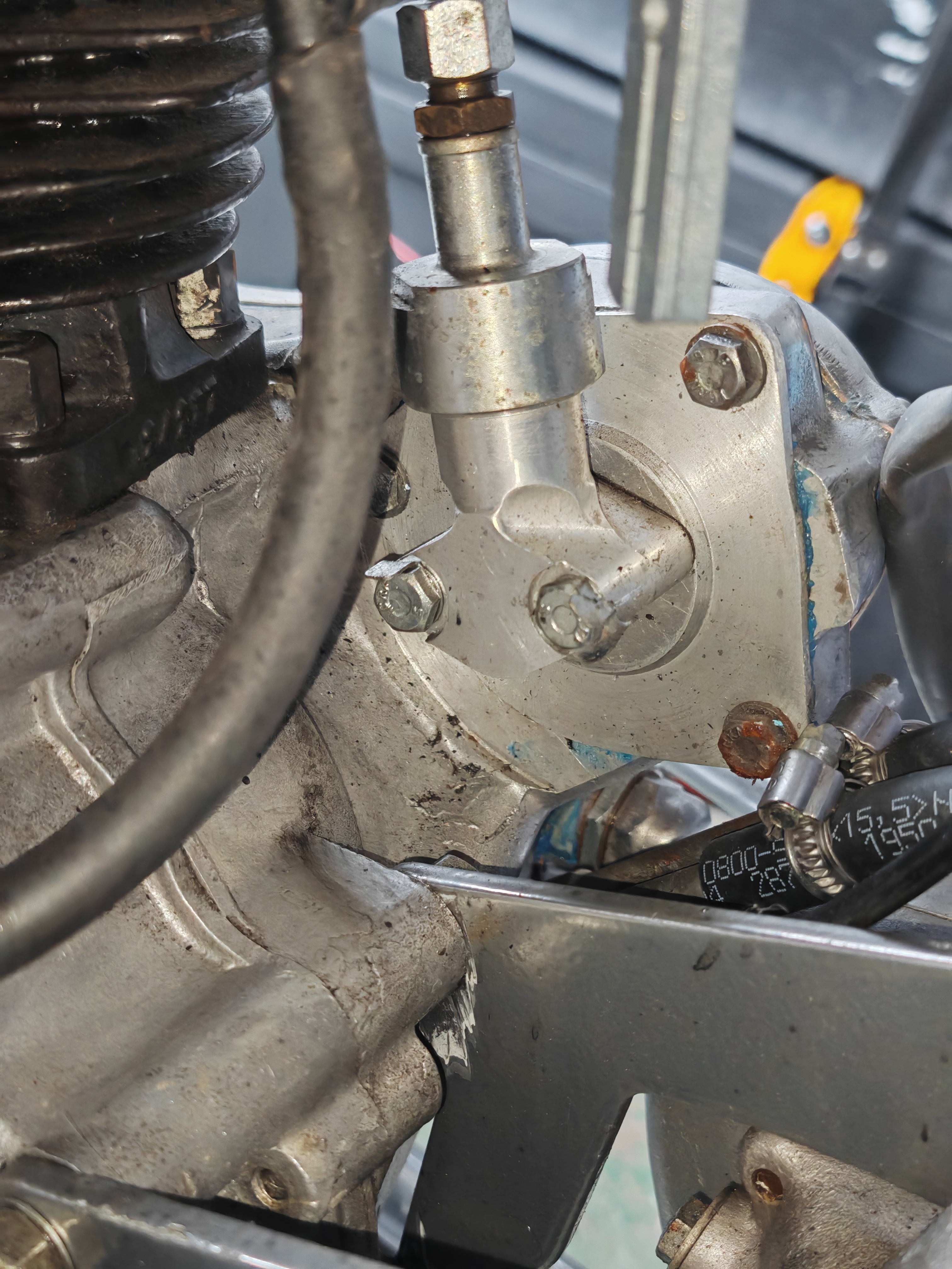
I've seen that the company Jan mentioned that make a breather that replaces the large diameter sump plug, do in fact make a special version for the early Commandos which fits around the frame brace. I'll see if I can find the details of this later for you, as I think this is a good option instead of either of your existing breathers. It costs a fortune though unfortunately!
- Log in to post comments
Thanks again Graham, I know…
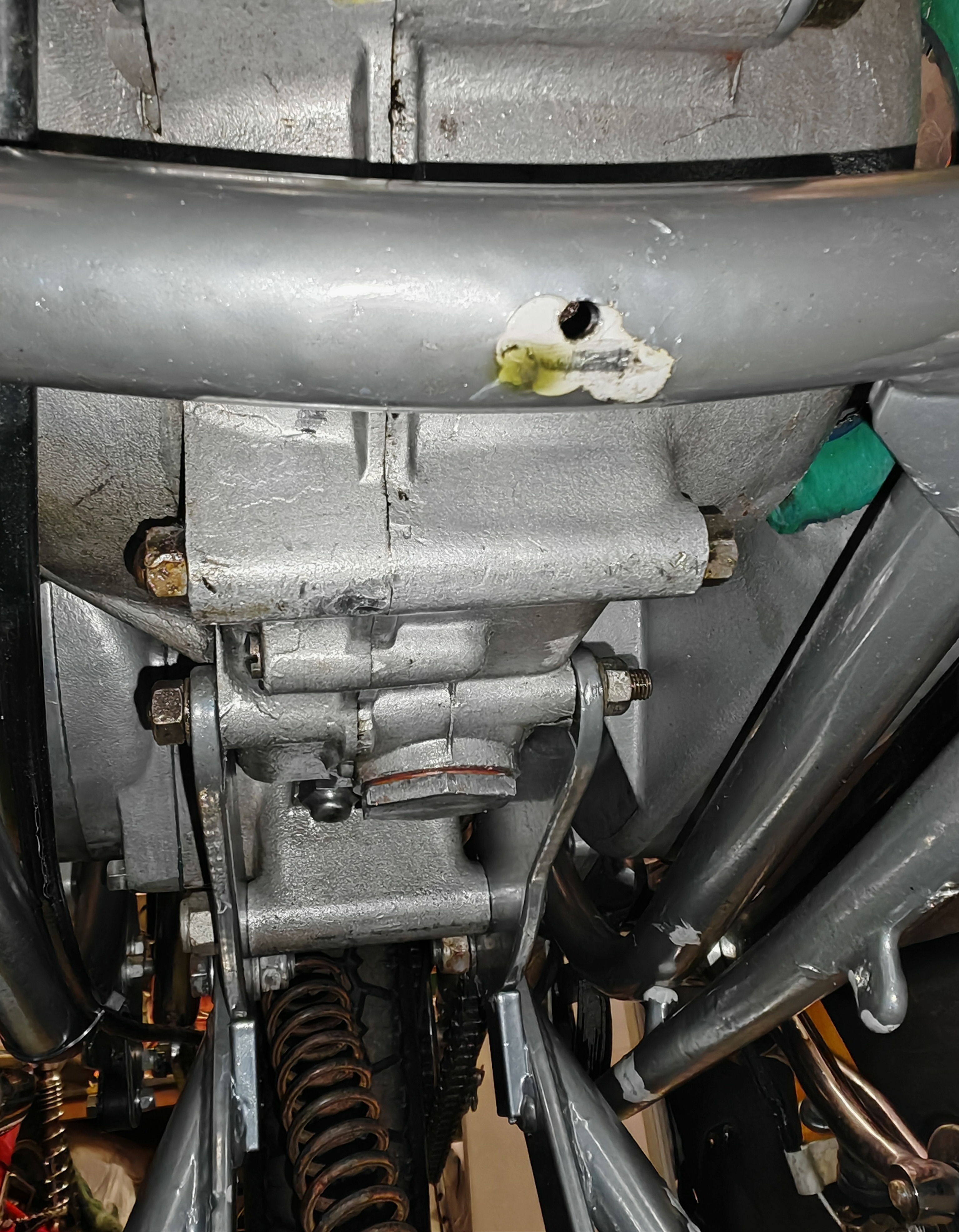
Thanks again Graham, I know what you mean about continuity of bore size, you can only get so many marbles through a pipe at once. I've stepped into the dark world of crankcase ventilation and as you say it's deep and emotive. I've read all the favourable reviews of the expensive Comstock / NYC sump type units but when I checked they're out of stock, maybe no longer being made. I've attached a photo from front to rear of the underside and I don't think I have the frame brace you mention that can interfere with their fitting.
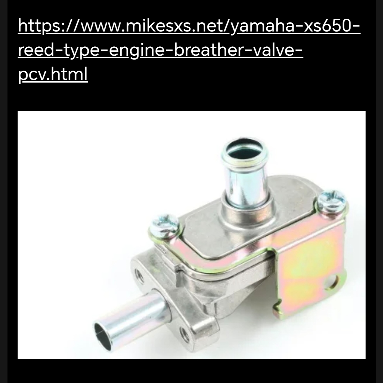
I also saw the XS 650 valve having favourable reports.
- Log in to post comments
Thanks Jan, are these in…
Thanks Jan, are these in line PCV's, do you have a photo of an example?
- Log in to post comments
70/71 commandos
However, beware of this very expensive sump plug/breather as it won't fit in front of the frame crossmember by the sump plug on the early Commandos.
- Log in to post comments
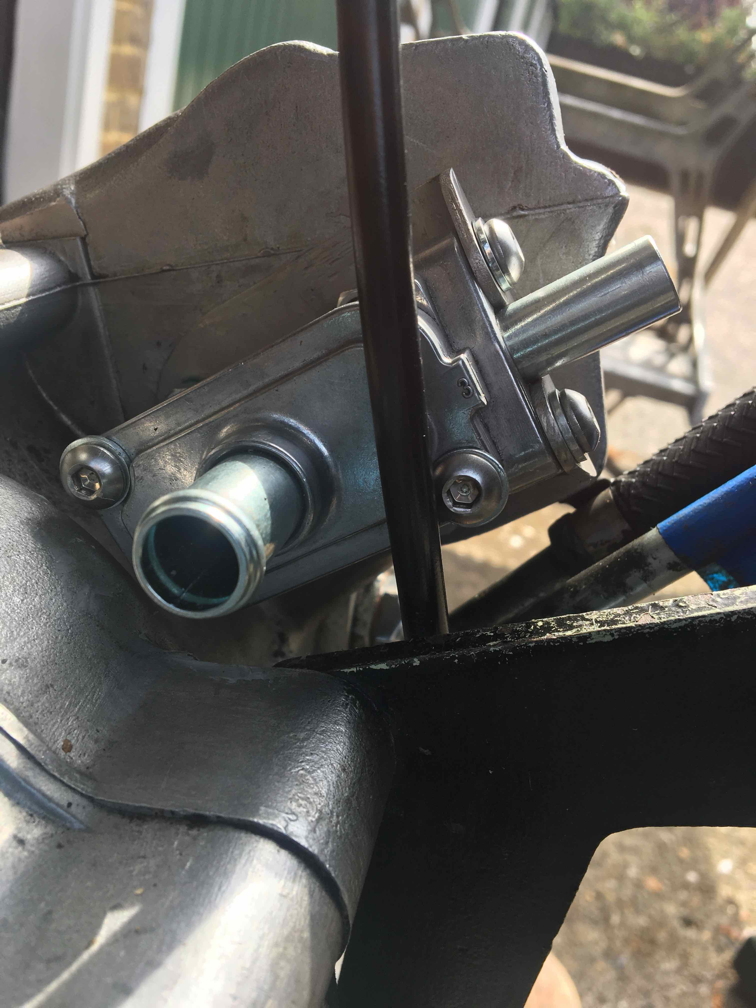
Here are pictures showing…
Here are pictures showing the fitting of PCV valve (supplied by Holland Norton Works) fitted to my 1972 Fastback. The inlet side is fed from the standard elbow on the back of the crankcase.
The bracket replaces the timing chest breather elbow fitted by a previous owner, to little avail since they neglected to provide the necessary communication with the crankcase …
- Log in to post comments
Thanks Julian, that's very…
Thanks Julian, that's very neat and quite discreet. I've searched for a Yamaha XS650 valve to no avail (UK) is that what yours is from? Also you mention it being fed via the standard crank case elbow, do you mean the one from the end of the cam shaft?
- Log in to post comments
PCV source
My PCV from Holland Norton Works is, I believe, the XS650 type.
On the feed to it, I should have been more explicit. For the 1972 models the factory abandoned the timed breather and replaced it with a fitment on the back of the crankcase. Follow this link
The breather elbow is composed of the parts indexed as items 46 and 47. As you will see, the output of the breather is moderated by a small bit of foam; the outlet pipe goes direct to the tank.
On my set-up I have retained the contents of the elbow. As mentioned, the pipe now goes to the PCV, and then to the tank.
I can't report definitively on the results of this arrangement since I have had the bike running for less than half an hour in total since completing the work (various other issues to sort out). However, no obvious problems have manifested themselves.
- Log in to post comments
Thanks Julian, a previous…
Thanks Julian, a previous owner has fitted 46 and 47 + to my '71 engine, along with the existing timed breather but I've not witnessed the results of the dynamic duo or more than likely, terrible twins combination yet, having only had it running for about 10 seconds before, as you say, other issues gained priority. I'll tell you what, you're never bored owning a Norton.
I've been onto Holland Norton and they have the valve in stock and I also noticed they sell an oil tank mounted ant-wet sump device, which no doubt will be another deep emotive subject of do's and don'ts.
- Log in to post comments
Breather elbow
At least the p/o has made a neat plate on which to mount the '72-type elbow. Assuming that they did not bother to make the necessary passages between crankcase and timing chest I would expect that the fitment will not do very much for either good or ill. Certainly I never noticed any problematic about the equivalent arrangement on my bike ('72 elbow on the '72 crankcase, and an empty elbow on the timing chest.
- Log in to post comments
Thanks Julian. The valuable…
Thanks Julian. The valuable description and information Graham Pickering gave me about the crankcase modifications looks to have been only partly done. I'm going to see how it behaves once I get it running armed with the details of how to remedy any problems that crop up.
- Log in to post comments
the oil tank valve
one of the better options, as you don’t have to operate anything manually. Colorado Norton produce it, and they have an vg reputation and have been using them for years.
- Log in to post comments
Thanks Jan. The bike came…
Thanks Jan. The bike came with a tap with a lever to shut off the oil, on which I'm not keen at all. I'm guessing the oil tank mounted type is fitted with a light compression spring acting on a ball.
- Log in to post comments
+1 for the HNW/CNW anti-wet-sump device
As you surmise, it is a Velocette-type valve … but arguably a more robust and up-to-date version of the idea.
The Velo item uses a relatively small diameter steel ball held against a metal knife edge; the HNW one has a larger ball seating on a (nitrile?) seat.
The latter arrangement circumvents the following possible issue: the Velo club spares scheme offers a nitrile-covered ball that circumvents the problem of worn knife-edges and consequent seepage. This has been criticised on the grounds that backfiring could drive the ball onto the knife-edge, which in turn could cut into and retain the nitrile covering.
There is also a small screw on the outlet side of the HNW valve that one can remove to prime the oil line to the pump. Personally I find that a long rod (e.g. stout screwdriver) through the filler cap can be used to lift the ball off its seat (turn the engine over with the plugs out).
- Log in to post comments
Thanks for your sharing your…
Thanks for your sharing your experience and information about that Julian.
- Log in to post comments


That engine, the crankcases at least, seem to be from an earlier Commando than '72. Both the things in the pictures are engine breathers but a 72 bike should not have the one at the front and the rear one should be at the bottom rear of the crankcases, although people do move them to where that one is. Are you sure the engine number is same as frame number as the number on the picture is an earlier number.