
Having found my advance retard mechanism unsurprisingly very worn I am researching electronic ignition and 12 v conversion. Having read many threads on this and Al Osborn's sage advice I am pretty comfortable with how to go about it. However, a couple of questions come to mind: What are the pros and cons of Boyer MkIV v Pazon systems and any top tips about fitting apart from the manufacturers instructions which I have read? I have seen comment that the Boyer rotor may not fit well - have people encountered this recently?
The Boyer Power Box seems a sensible addition - any feedback?
Is it worth including a Capacitor and if so is the Commando one advertised in NOC shop compatible and how does one wire it in?
Is there a 6 1/2" headlight available compatible with 12v Quartz Halogen or pre focus bulbs?
My original Wipac alternator continues to work and I know how to wire it in for 12v. However, I suspect it is now 54 years old and may wrap its hand in working that hard! I believe a modern Lucas alternator stator will fit - if so which one? I believe the crank is 1" diameter - is there a replacement rotor available or can I use my existing one?
My experience with Lightweights is nothing is ever as simple as you think and someone has been there before you so any other top tips would be welcome!
Cheers Nick
Nick-there is a comment el…
- Log in to post comments
Thanks for all that Alan,…
Thanks for all that Alan, really helpful feedback! I saw the comment about the Boyer pick up and the length of the wires compared to the Pazon system. Are there any other pros and cons between the two? Fear not I have looked at your product list and your advice about soldering v crimping! As for the capacitor I would go for a stand alone one - at least you can change it if it fails!
Nick
- Log in to post comments
Sorry Alan, just seen your…
Sorry Alan, just seen your post on 'electrical' ref pros & cons of the two systems. I'm keen to know if the Boyer base plate issue has been rectified - does anyone have recent experience with their Mk1V system?
- Log in to post comments
When I got my original Boy…
When I got my original Boyer system it came from Mick Hemmings. At that time there wasn't any "official" electronic system for a Lightweight. It was MH who told me that I could use the Boyer electronic box/wiring for a Commando matched to a BSA Bantam base plate as the Commando base plate didn't fit the Lightweight. (This was a long time ago -probably 25 years ago- and it still works).
So possibly the 'problem'with the original Boyer was that the base plate and the rotor were really designed for the Bantam.? ?
Around the same time we also used a Commando Boyer on a race BSA Starfire, i.e a single cylinder with a two plug head. It used up two or three batteries for a day's racing but otherwise worked well. Again this is ancient history but it seems to say that the one electronic box was used for many different applications and just modified accordingly.
Patrick.
- Log in to post comments
I recently purchased a Boy…
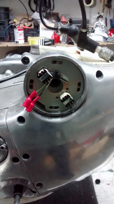
I recently purchased a Boyer base plate from them for my Navigator. Here you see it installed. No major issues with it. I have a black MK III box for a Commando and it is running fine so far.
Must admit not too many miles on it because it is not registered for road use yet..
- Log in to post comments
Hi Ulrich, the base plate…
Hi Ulrich, the base plate certainly fits nicely - does the photo show it with the rotor in place behind it and if so is there enough clearance? Did you buy the MkIV or Mk III system for the Navigator and did you have to buy the base plate separately?
Thanks for the help!
Nick
- Log in to post comments
Nick, I got the bike with…
Nick, I got the bike with a Boyer box and a base plate from a Commando somehow made to fit. The Commando base plate is smaller in diameter and the PO had drilled or widened the holes in it to make it fit to the larger Navigator ignition.
I kept the black box and only ordered the right base plate. I guess at the time the bike was converted to twelve volts and the Boyer ignition there was no Lightweight base plate available.
Must have been in the early ninties.
Here is a pic with the rotor and base plate. Enough clearance.
I only had to sand down the outer diameter of the base slightly plate to make it slide easier in the ignition housing for adjustment.
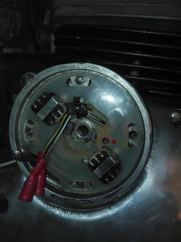
Here is a pic with the rotor.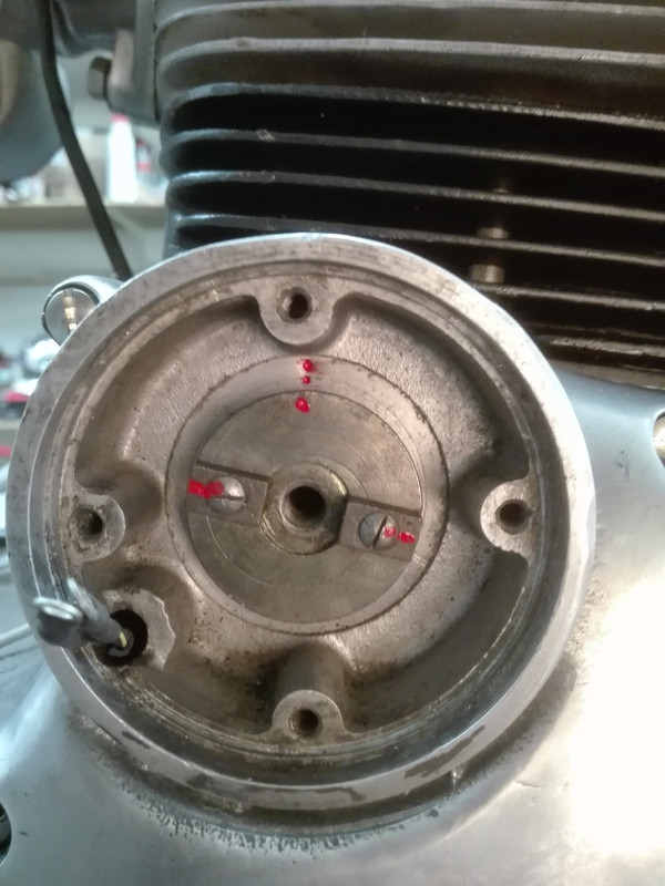
- Log in to post comments
Just to complete the pictu…
Just to complete the picture....it seems the rotor is well close to the back of the PU plate. The way I got out of this many years ago is to have the rotor taper re machined a 'tads' smaller so that the rotor sits further into the engine.
As far as the PU plate fitting within the timing cover I would like some qudos for this as I asked BB to make this plate for the Wipac ignition as oposed (another naf word miss spelt but NOT corrected as no spell checker on the forum) to the Commando/twin one. Unfortunatly I cannot remember when that was but it was some time ago. But persons stiil tried to fit the smaller twin plate. The actual circuit part is identical it is just the fibreglass plate which is bigger.
- Log in to post comments
Thanks for all that histor…
Thanks for all that history Alan and Ulrich, well done - clearly lots of ingenious adaptation going on over the years by you guys to get your lightweights running smoothly! Do you know if the current purpose built BB MkIV systems fit the lightweights without these base plate problems? I haven't heard any complaints about the Pazon system 6 or 12v systems which seem to fit straight from the box with the added advantage of longer wires which can be cut to fit individual requirements and safe operation down to a lower voltage.
Nick
- Log in to post comments
I didnât have access to a…
I didnât have access to a lathe so rather than trim the rotor to maintain the clearance I fitted small washers behind the plate which extended the pillars sufficiently to get the clearance, but they were fiddly little blighters to get in there!
- Log in to post comments
I'll speak up for Pazon w…
I'll speak up for Pazon which is running fine in my Electra.
When I first fitted it I noticed there was very little clearance between the rotor (nicely made item on the Pazon) and the back of the pick-up plate. Using a fine file, I reduced the projection of the highest pins and solder blobs under the pick-up plate to increase clearance slightly. The pick-up is easy to fit and fits well.
Set up by aligning a red dot on the rotor with a small window in the pick-up plate. You need a timing disc and TDC finding tool. Easy. Started and run fine.
However, you are only likely to be +/- 3 degrees if you rely on the red dot.
I'd recommend use of a timing disc and a strobe. The extra accuracy seems to give a much better engine on the Norton Lightweight.
One feature let me down. I used only the tiny terminal block provided on the pick-up to attach the two wires. With heat and vibration the connection became unreliable, leading to misfire and then cut-out. I now solder the two wires to the alternative solder pads on the P/U. Pazon provide these pads next to the terminal block for a reason, and it seems to be a wise choice.
Easier maintenance or reliability? With an HGV tailgating you and the engine cuts out, the decision becomes easy.
Happy riding
Peter
- Log in to post comments
Well that is interesting;…
Well that is interesting; Dan has a late model Boyer on which the points plate needed spacing and Peter has a Pazon which also required similar fettling. Sounds to me that the rotor/points plate on both of them was not specifically tailored for the Norton engine. (easy enough to make fit but surely the customer could expect better after all these years in production).
Several people have said that the Pazon operates down to lower voltages but if you read the specifications both of them claim a similar operating voltage range.
Patrick
PP. Peter, I know what you mean about being tailgated by a HGV. If you are on a Jubilee (on the A19) said HGV can not only out accelerate you but they can also out brake you. It makes you wish you were back in 1960 when a Leyland Octupus was hard pressed to get to 30mph.
- Log in to post comments
Previously Nick Clarke wro…
Previously Nick Clarke wrote:
Thanks for all that history Alan and Ulrich, well done - clearly lots of ingenious adaptation going on over the years by you guys to get your lightweights running smoothly! Do you know if the current purpose built BB MkIV systems fit the lightweights without these base plate problems? I haven't heard any complaints about the Pazon system 6 or 12v systems which seem to fit straight from the box with the added advantage of longer wires which can be cut to fit individual requirements and safe operation down to a lower voltage.
Nick
With regard to the BB IV or III, these are only Model numbers given to the Black Box ie the ignition amplifier. The PU plate is the same in both of them. The MKIV was developed as the MKIII had issues with 'wandering' timing when the battery voltage dropped and on a Commando thus casing kick back and often a broken sprague. Hence BB developed the MKIV. So either will do on the Lightweights and I am even suspicious that early MKIII didn't have a wandering timing either?
Further on these threads I believe there was a thought that watching the strobe flash onto the 'red dot' through the plate timing hole did not see the red dot move, actualy it does move but of course only half what the crank shaft timing does.
- Log in to post comments
Thanks for all the advice…
Thanks for all the advice and history Alan, Patrick, Peter and Dan - fascinating and a typical lightweight saga! I have bitten the bullet and ordered a Pazon 12v system - it means a new battery, wiring harness, rectifier / voltage regulator, capacitor and bulbs but on balance worth it for more accurate timing and hopefully more reliable electrics and better lights! I will let you known how much clearance there is between the rotor and pick up plate - there should be no excuse for a poor fit if it is well designed and manufactured.....!
- Log in to post comments
Nick, I installed a Pazon…
Nick, I installed a Pazon 6v on my Jubilee recently and I noted on another post that the base plate is not a good fit. I assume the Navigator has the same size points housing as the Jubilee. The problem I had is the slots in the Pazon base plate do not align with the post bolts that hold the outer cover on. If you widen the slots to fit there may not be much 'meat' left on the base plate. You may need to fit repair-type washers, such as pop-rivet washers under the post bolts to spread the load on the base plate. Do not overtighten the post bolts or you may crack the base plate.
Make sure you have an even gap around the base plate or you may have the rotor magnet rub against the pick up studs on the base plate.
I suggest you set the advance on the rotor using a timing guage on the alternator side then fix the Pazon pick up to the cam with the red dots at 12 and 6 o'clock then fit the base plate with the dot centred in the hole in the base plate. This should give a reasonably close set up. Howver, as you will have the alternator rotor exposed it is worth checking the timing with a strobe using a point fixed on the rotor. I marked TDC and 32 degrees before TDC on my alternator rotor aginst a fixed point.
Dennis
- Log in to post comments
Thanks Dennis, I've just…
Thanks Dennis, I've just received my 12v system and will check all of those issue very carefully - my aim is to check the static timing with a strobe once I've found a really accurate way of transferring the timing mark on to the alternator rotor - my timing disc is far too big so hunting down a smaller one! I will report back how it all goes.
Nick
- Log in to post comments
Nick, I apologise if you a…
Nick,
I apologise if you already know this but find TDC on the engine for the left cylinder (alternator side) using a probe down the plug hole. I used a dial gauge but a pencil will do just as well to determine the high point of the piston with both valves closed on the compression stroke.
You can tell which is the compression stroke if you put your finger tightly over the plug hole as you rotate the engine by hand.
Having determined TDC, attached the timing disc to the rotor stud (mine is just a press fit). Use a piece of wire attached to the head and bent downwards to act as a pointer on the disc and with the engine at TDC rotate the disc to register zero degrees against the pointer.
You can now mark the rotor at any convenient point against a fixed point on the casing (in fact I made a metal pointer that attached to the alternator stator using the stator nut at about seven o'clock to hold it in place). That is TDC marked on the rotor.
Now without disturbing the timing disc, rotate the engine backwards by hand by the desired amount against the pointer attached to the head (32 degrees in my case) and make another mark on the rotor against the same fixed point. You have now transferred marks for TDC and 32 degrees before TDC to the rotor magnet to view with the strobe.
Dennis
- Log in to post comments
Ulrich supplied this infor…
Ulrich supplied this information previously on how to make a pointer for the rotor for strobe timing.
- Log in to post comments
I strobed it with the timi…
I strobed it with the timing disc in place, mine was locked behind the rotor nut.
- Log in to post comments
Thanks Dennis, your experi…
Thanks Dennis, your experience confirms the process I have used in the past although I use a TDC finding tool that screws into a spark plug hole. Thanks for the copy of Ulrich's pointer drawing - it is the one on Alan Osborne's web site so I'm going to make one up tomorrow. As for the base plate, mine is exactly the same - a snug fit in the casing but the slots are slightly out of line with the mounting screw holes and will have to be carefully opened out and suitable washers used to spread the load. Rather disappointing when that sort of accuracy is easy to achieve in manufacturing! I just hope the rotor isn't too close to the back of the base plate when I fit it.....
Nick
- Log in to post comments
Dan, what size disc did yo…
Dan, what size disc did you use? I only have the traditional Wassal's one which is much bigger than the rotor so I will have to make up a pointer and bolt it on to one of the chain case screw holes or similar. Do I remember you mentioning you down loaded one from the internet, reduced it in size (approx. 7cm diameter by my measurements), printed it off and attached it to the rotor? If so did you use Alan's pointer bolted to one of the stator studs?
- Log in to post comments
Anteriormente Nick Clarke…
Anteriormente Nick Clarke escribiÃ?:
Dan, ?quÃ? tamaÃ?o de disco usaste? Solo tengo el Wassal tradicional, que es mucho mÃ?s grande que el rotor, asà que tendrÃ? que inventar un puntero y atornillarlo a uno de los orificios de los tornillos de la caja de la cadena o similar. ?Recuerdo que mencionÃ? que bajÃ? uno de Internet, lo redujo en tamaÃ?o (aprox. 7 cm de diÃ?metro segÃ?n mis medidas), lo imprimà y lo peguÃ? al rotor? Si es asÃ, ?usÃ? el puntero de Alan atornillado a uno de los pernos del estator?
- Log in to post comments
I thought a final update m…
I thought a final update might be helpful for anyone else considering these upgrades. I have just finished converting my Navigator to 12v electrics using an A1Reg Voltage Regulator / Rectifier and Capacitor from Alan Osborn and a Pazon Sure Fire PA2L electronic ignition system, a set of 12v bulbs from the NOC and retained the 6v horn (which can now be heard!). After a careful study of the wiring diagram, the switches and almost new 6v harness I removed or isolated redundant wires to the points, charging system and rectifier. I bolted the regulator / rectifier to the back of the vertical main frame member using an existing hole and tie wrapped the electronic ignition box and capacitor on the inside face of the right hand horizontal main frame just behind the front seat spigot. Using the wiring diagrams provided by Pazon and Alan I wired everything in using soldered brass nipples and original style connectors, adding a 25 amp fuse. After a bit of research I realised the Yuasa YB5L-B 12v 5.3 AH battery from my Royal Enfield Bullet is identical in size to the 6v battery solving that problem! Unlike reports about the Boyer Bransden system the Pazon rotor fitted perfectly behind the new back plate / ignition trigger assembly but I did have to use a small curved file to open the four mounting slots out about 20 thou to allow the two retaining screws and pillar screws to fit. Being a neurotic I used a multi-metre to check that I had the polarity of the wiring to the ignition correct before I connected it up and switched it on!!! Setting the static timing using the red dot on the rotor lined up with the timing hole in the back plate was incredibly simple using a simple TDC tool from Norvil which screws into a plug hole, a Wassel timing disc on the end of the crank and a pointer I cut out of thin ally and bolted to one of the upper chain case bolt holes. To my astonishment it started first kick, the lights and horn all worked and the alternator showed a healthy charge! Although now 12v it was just too difficult to connect my timing strobe power leads to the bike battery so I used an old car battery. When I checked the timing using a strobe it was advancing correctly and only 1.5 degs out which was a pleasant surprised. Fine tuning took a couple of attempts because tiny movements of the back plate were required. A rather rash 20 mile test run to the pub and back last night shows the lights are transformed and the engine is smoother, picks up and pulls more willingly and ticks over like a metronome! All in all well worth the effort and cost. In the future I will design and make a bespoke wiring harness and plate to mount the various electrical components on to tidy the whole thing up but for now I am going to enjoy riding the bike to check reliability and identify any unforeseen snags! A warm thank you to Alan Osborne and all of you for your sage advice which has helped me transform my Navigator!
- Log in to post comments
Apologies for not answerin…
Apologies for not answering your question, I must have missed it! But you seem to have done it pretty much as I did, I did indeed download a timing disc and stuck it to some stiff cardboard. (Cheapskate!) The only dif was that I used a dial gauge to find tdc, mine also started first kick! As it did this morning!
Al didnât like my washer trick, but without accurate tools to reduce the rotor I felt it was a simple solution and has worked well enough so far! When I do my Navi over the winter ill try the Pazon instead of the Boyer.
- Log in to post comments
No problem Dan and thanks…
No problem Dan and thanks for confirming that. I looked back and found your advice on downloading a disc and tried it, I just couldn't find one clear enough in that size to be comfortable about reading it that accurately. The larger Wassel one worked fine for static timing but the plastic isn't that strong and eventually started to break up when I ran the engine to strobe it. Long term I will persevere with your idea so I can mark TDC and 24 degs on the alternator rotor to line up with a timing marker clamped by one of the stator bolts like the one Alan shows on his web site. Did you have the heads off to use the dial gauge to find TDC? Good luck with your Navi, even though my mechanical advance retard and springs were in reasonable condition and the timing as accurate as I could get it with the wonderful point system I was immediately impressed with the improvement in engine smoothness, pick up and performance. Overall it is just a happier engine and more pleasant to ride!
- Log in to post comments
On my bike I painted narro…
On my bike I painted narrow white lines across the rotor and stator when the engine is at the correct location, rather than a metal pointer. They show up well even on a cheap strobe. I put two bits of masking tape close to each other to get neat alignment. I think I used typing correction fluid (although permanent solvent type might not be available nowadays?).
- Log in to post comments
Youâve got to love old sc…
Youâve got to love old school tippex, very useful stuff!
I managed to use the dial gauge with the head on (and in the frame) by clamping it vertically and using a long rod to reach in the head.
Dan
- Log in to post comments


Nick-there is a comment elsewhere on this site re the Boyer pickup. The Boyer Power box, is over priced and high in failure rate so I stopped selling them some years ago. There are several other regulator/rectifiers on the market and a lot cheaper....Lucas stators are alleged to be fitted to the Lightweight, but there is no Lucas type rotor for 1" crank so you are stuck with the Wipac which seems to work very well considering its years, and I would also keep the stator.
I have an H4 headlamp in my Electra but the 61/2 headlamp is of Japanese origin!
As for fitting a capacitor yes but not much point with the Boyer Power box as it is already inside.
By the way it seems you have read my Lightweight advice but not my product list.