
I am helping a friend sort out the electrics on his 99. It has a 6V Lucas E3L-L-1- C dynamo. It is positive earth.
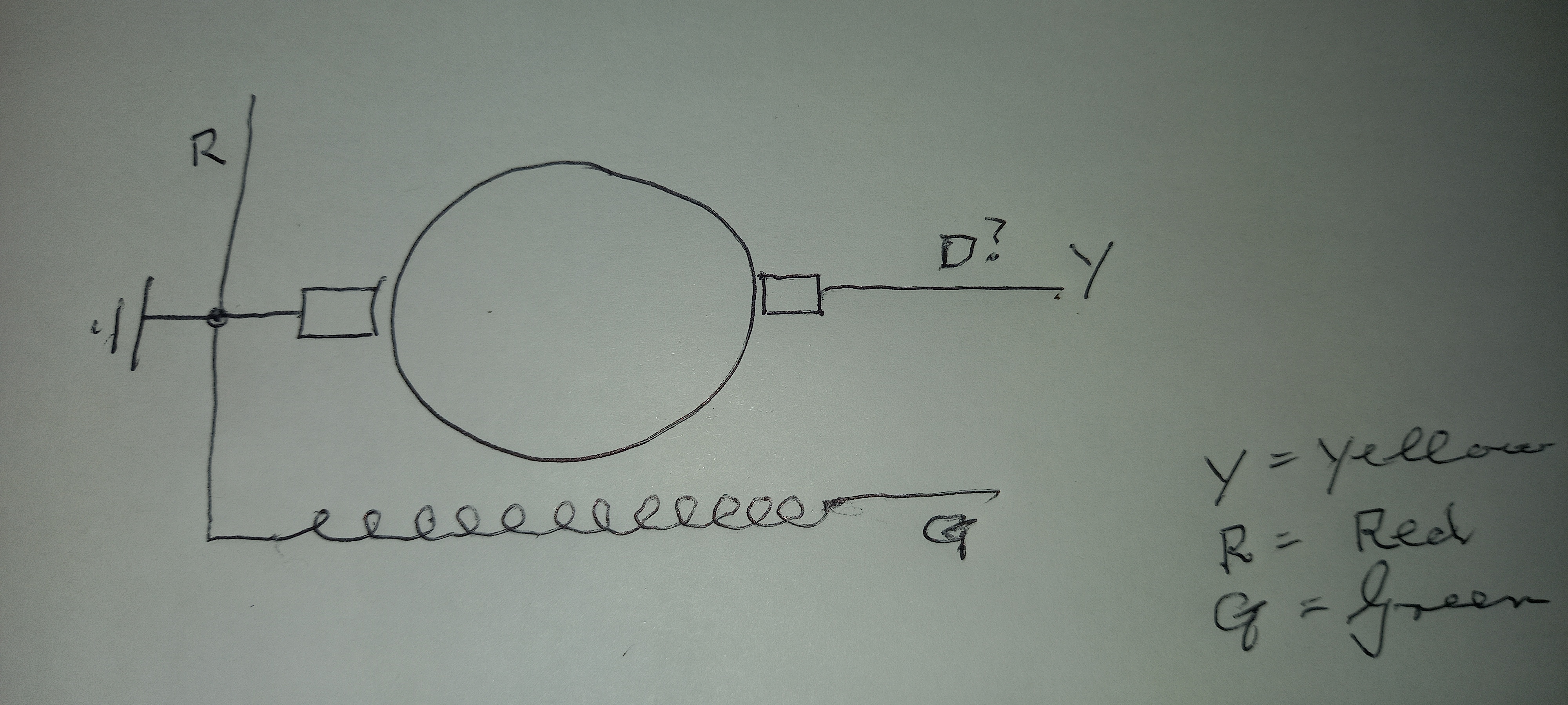
A PO has fitted the wires as shown in my sketch attached.
Can someone tell me if the connections are correct, and how it should be wired into the bike?
I have now done the test of…
- Log in to post comments
Several points
You must spin the dynamo in the same direction that it spins on the bike. Do NOT rely or consider the arrow on some dynamos is correct. It was put there by the manufacturer maybe some 70/80 year ago. The direction of rotataion might have been changed several times since. What is a 'negative cucrrent across the field' ? Current is through-Voltage is across.
To polarise a dynamo you connect the dynamo as you would use it on your bike ie Positive to earth then apply the live (negative) to the Field coil for a moment or so, on removal the wire will make a small spark, the dynamo is now polarised. The Field coil is 3 to 6 ohms, while the Armateur (D) will read 'short circuit' and it will joggle when you turn the Armateur, which proves the brushes are passing the com. When spun in the direction it would on the bike, with the D connected to F the dynamo must give a bright light (headlamp bulb).
Connections on the bike? The D and F go to the regulator.
- Log in to post comments
Thank you Barry and Alan
It is possible that I didn't spin it fast enough. I did turn it anti-clockwise, as the Dominator does.
Alan, the statement "negative current" was an error - it should have been "flashed the battery negative across the field coil to positive earth"
There was a spark on touching the wires when polarising the field coil but not on removal. I touched the wires only once, for about 1 second. I'll do it a few times tomorrow.
I have now measured the resistance of the field coil - it is 3 ohms.
The resistance across the brushes one to the other is about 50 ohms (I don't know if that means anything). They are new brushes so maybe haven't seated properly yet.
From what you have said, I think it should work.
I'll try again tomorrow paying more attention to your comments.
Thank you again.
- Log in to post comments
Your resistance is far too high.
D should read short circuit ie very low ohms. So 50ohms is far too high. Are you reading your multimeter correctly? Did it 'toggle' when you turned it? Brushes should make contact straight away.
- Log in to post comments
More results
I found that the one brush was sticking in its holder.
Correcting that, the resistance across the com, one brush to the other, is zero ohms.
I haven't been able to do a running test yet, but joining D and F and measuring the voltage there to earth, gives me 10 times more than before fixing the brush. This is by spinning dynamo by hand. Still only measuring millivolts. Probably means nothing but for me, encouraging. I'll do a running test in the next few days.
- Log in to post comments
That bulb...
That bulb needs to be a head light bulb 12V if you can. It should glow very bright ie a bright 40W bulb means you have 40W. Voltage on a mutimeter does not mean you have any amps. Of course you must polarise the dynamo first.
- Log in to post comments
Polarising
Yes, I did polarise it, flashed it three times, a healthy spark when removing the lead.
I'll test it soon, I quite looking forward to seeing it work - I hope.
Thanks again
- Log in to post comments
Finaly
Finally, I managed to get around to testing it properly (moving house is time consuming, specially with 18 years of accumulated motorcycle parts, tools, etc)
I fitted it to the engine and put a headlight bulb across the DF joint to earth.
At idling, the bulb lit up and grew brighter as the revs increased.
So all seems to be well.
Thank you all again for your help and advice.
- Log in to post comments
I nearly forgot...
I nearly forgot.....One point with regard direction of rotation and testing of Dynamos. After you have 'splashed' it and connected D to F if you do NOT get any output. You might get an output if you turn the dynamo in the 'other direction'. Easy enough if you are testing, but awkward on your engine. The answer-output from the dynamo is subject to the relationship between the Field and the Armateur. If either Field or Armateur connections are reversed then the dynamo's output will only be if the direction of rotation is reversed. ie when putting a dynamo together the direction of rotation needs to be known so that correct connections can be done.
- Log in to post comments
Thank you Alan..
.. for this. It is exactly where I am now.
Running the engine with D and F connected together gives a good light when connected to earth.
When connected to the regulator, however, there is no output voltage.
So, I suspect that the regulator is faulty. As a test, I connected a battery to the two wires I think are the D and F feeds into the reg. My reasoning is that I should get a voltage across the two output wires. Result - nothing.
My question now is how to connect the dynamo to the regulator. Possibly the existing one was damaged by an incorrect connection and I don't want to destroy the new one I'm buying.
The dynamo is running according to the arrow on it. The F wire is connected to the field coil.
I've been offered a 6V positive earth reg but I want to be sure I connect it all properly.
For a positive earth 6V system, if I connect the gen D and F incorrectly to the reg, will it destroy the reg?
- Log in to post comments
The regulator ...
...is a locally made one so it may well be faulty.
I'm ordering a new one which apparently is well marked - it is for 6V positive earth.
- Log in to post comments
Barry
Most regulators just control the MAXimum voltage applied to the battery, so at low revs there will be some output, in the form of a rising voltage on the battery, especially if you lower the battery voltage by switching some lights on.
Richard-as Ian says-what type/make of regulator do you have? If it is one of mine I am very happy to get involved on a personal level.. If it is from another recent manufacturer then the supplier needs to be contacted. If it is the older solenoid type, then it is over to you or finding a dynamo or regulator repairer. Of course if you buy a new regulator it will come with fitting instructions! Guessing on here is not the thing to do.
- Log in to post comments
Thank you Alan..
The regulator was made by a private club member, he sold a few of them.
He's no longer with us.
I have no information on which wires are for which, and I don't know if it even works, so it's going in the bin.
All my talk above was to see if there was a way to test it easily, but I won't waste any more time on it.
But as a test, will connecting a battery to the reg in place of the generator, will the regulator show an output voltage?
Thank you all.
- Log in to post comments
NO
NO waste of time. Regulators supply electricity to the Field circuit to energise the dynamo which in 'turn' gives a generated output at D which is controled by the regulator and supplied to the A and hence to the battery.
If you are looking for something to do......then Pg 97 of Dominator Service Notes has a detailed exposea on the solenoid regulator and its repair/understanding. Not written by me.....I would argue that you need a good understanding of electricity if you are going to delv this deep.
- Log in to post comments
That's an excellent write up Al...
... a bit of a shame it's hiding in the Domi service notes. Admirable though that is I've never thought of looking in it - perhaps I should take my blinkers off.
I've always found trying to test a Lucas regulator in situ to be problematic - they're usually difficult to access and I don't like revving the engine up and down to avoid upsetting the neighbours. I found a lttle variable voltage device on ebay which is far more controllable and makes setting the regulator and cutout very simple.
- Log in to post comments
Fine
The variable voltage power supply can do this job. BUT you would have to understand the cut in/out voltages, and the regulating voltage. Also, if you are going to try to set these up and you know the voltages you want, but do you know what to do if they don't work?? Fine if you do it for yourself and get it wrong, just ride home in the dark! But guesing is NOT the way to go.
- Log in to post comments
I just...
... followed the Lucas instructions but using the voltage supply off the bike to check sutout and regulator operation. Seemed to work well for me and once fitted on the Norton are fine. I understand why people fit solid state devices but the old electro-mechanical ones were in use for many years and did the job well enough.
- Log in to post comments
Thank you all.
... for your help with this.
It looks like my main problem was brushes not moving freely in their holders.
With that attended to and a new solid-state regulator, everything seems fine.
- Log in to post comments


I have now done the test of connecting green and yellow together, spinning the dynamo with an electric drill and measuring the voltage between GY and earth - red in my case.
Voltage with the drill spinning at maybe 500 rpm is only a few millivolts.
I have also tried to repolarise the unit, by flashing a negative current across the field coils. While there was a spark when touching the wires, it has made no difference.
Somethings wrong. What should the resistance across the coils be - can I measure it with a multimeter? Is it time to send it to a specialist?