
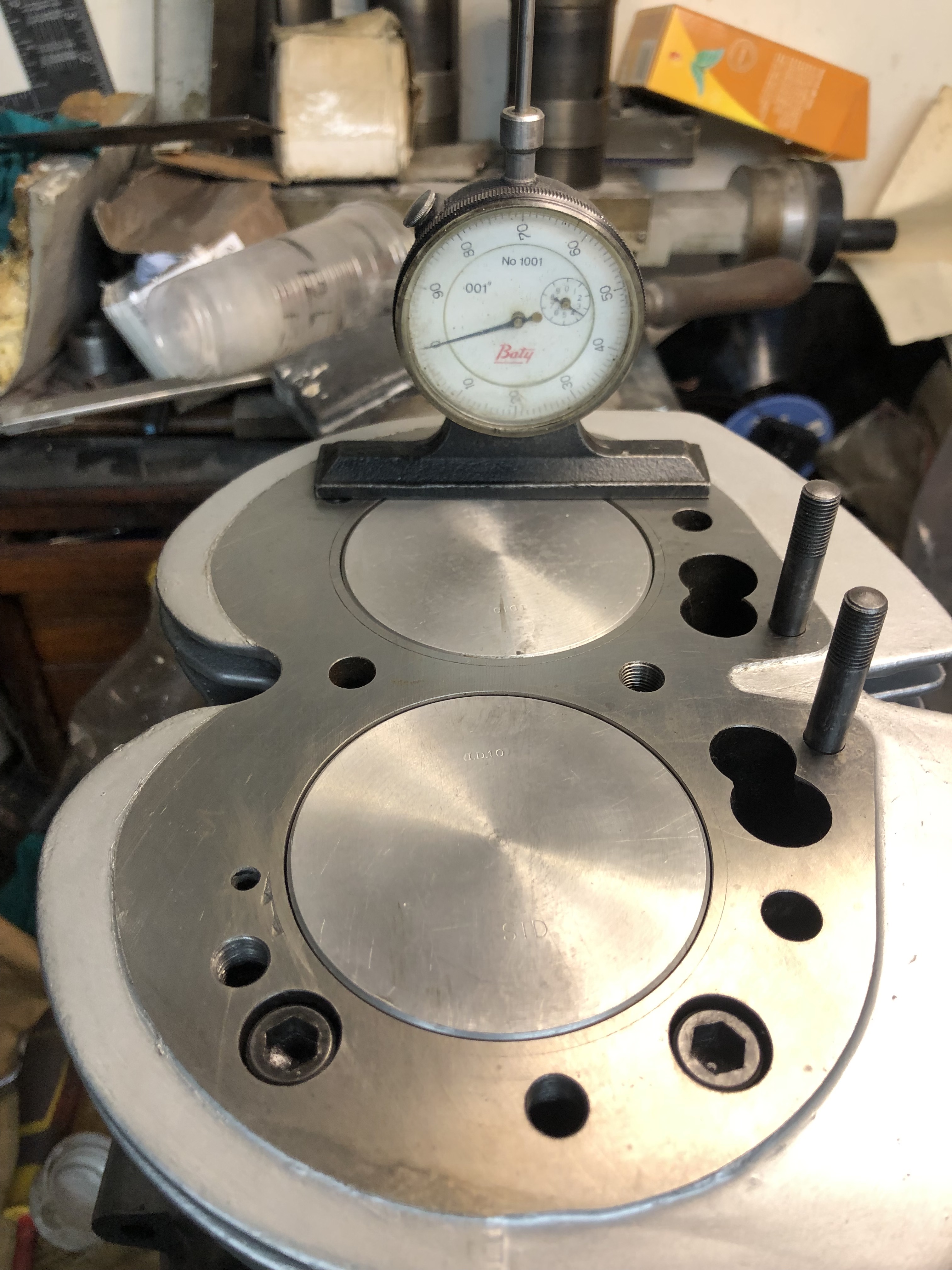
I've assembled the crankshaft into the cases on my 850 engine - fresh grind, new mains, new shells, new new AN conrods, N.O.S Hepolite pistons(std), new liners fitted. I noticed that the T/S piston wasn't level with the top of the Barrel. The barrel head face is parallel to its base. As in the photo I've put a drop clock on the head face of the barell and and zero'd the clock on the outer side of the D/S piston, Moving the clock across to the inner side of the same piston I got -0.004", inner side of T/S piston -0.0015 and outside of this piston +0.007". So the D/S piston is tipping over 0.004" and the T/S 0.0085" - is this normal?
Con Rods
Piston crown heights can vary depending on compression ratio.
But are your conrods a matching pair? Is it possible that you have different length con rods?
Also possible.......the crankshaft halves are not a machined pair and one of the Big End pins is slightly ahead / behind the other. Like crankcases they should have matching machine shop numbers on each cheek.
- Log in to post comments
Problem Cranks
When purchased, my 850 Mk3 turned out to have one big end 0.20" higher than the other. I took it to Steve Maney who was offering a re-dowelling and alignment service at that time but he said that it was too bad to do anything with.
I suspect that it had been a replacement as it lacked the Mk3 timing plug slot...Maybe a factory reject. A lot of duff parts crept into the supply chain after the factory closure.
- Log in to post comments
Cases?
I bought a matching pair of Mk3 cases, both stamped the same, very little use. When checked the main bearing housings were out of line. It took time, but they were clocked up, bored oversize with both inline, and a bronze bush inserted and bored back to standard size.
It would probably cost more than a new set of cases to do it now.
Quick and easy test, a sized bar through both small ends to see if the rods are the same length, then bring it down to the top of the cases to see if one side is higher than the other
- Log in to post comments
This doesn't help.....
This doesn't help but I have seen this same 'misalignment' many years ago with a commando. Never did work out what was wrong, but as it had run ok and continued to run, we 'moved on'
- Log in to post comments
Measuring four variables
Crank, rods, pistons, cylinder. Start at the base with crank angle comparisons. Then component matching. Long slow process to get the data but it may be accumulation of errors that could be eradicated by swapping components.
Jon
- Log in to post comments
Fascinating, I'd like to know as well...
Crank angle comparisons, sounds like something Anna would come out with. Please tell me what they are.
- Log in to post comments
You have two throws of the crank…
Bolted to the flywheel. Whilst they are not adjustable, the make up of the crank may have the left and right parts a degree or so out of alignment resulting in a different stroke height for a given rotation. This would happen if the crank was made up of parts not machined together when built.
Jon
- Log in to post comments
Just a long shot, I notice…
Just a long shot, I notice the barrel has been sleeved. Is there a chance one sleeve might have moved up a couple of thou, or after sleeving has the barrel face been skimmed off square?
Dave
- Log in to post comments
Both wrong.
Look closely at the tops of the pistons, the RHS side of both is UP while the LHS is DOWN. If it was a crank pin up/down then the whole piston would be UP down to suit, ie one piston up/down. IF the rods were bored out of alignment ie big end/little end not parallel this could cause it, but it could also cause the pistons to be badly out of square such that I think they would rub-cause lots of grief. The idea that the barrel is skimmed on the 'slosh' is possible-but when I saw this (some years ago) it was on a 'straight from the factory' engine. So unfortunately this (along with several others) is a factory miss-alignment. But still unknown.
- Log in to post comments
Photographs can be very…
Photographs can be very misleading. Angle of shot, lighting, shadow reflection, all play a part.
could this not simply be a case of a stack up of tolerances, particularly the piston down machined heights from gudgeon pin centres?
- Log in to post comments
NO
This doesn't help but I have seen this same 'misalignment' many years ago with a commando. Never did work out what was wrong, but as it had run ok and continued to run, we 'moved on'
No this is not a photo misleading, I have seen this many years ago in person....the piston tops are both a few thou up/down with respect to the barrels. ie the pistons are 'on the slosh' compared to the barrels.But not a barrels top miss surfacing. Possible a barrels mounted sideways bit. But how?
- Log in to post comments
hello ,does the flywheel…
hello ,
does the flywheel only fit the one way round.
barry
- Log in to post comments
I suspect if we all checked…
I suspect if we all checked our engines with an engineers critical eye we would find plenty of worrying discrepancies. In the past we would have shrugged our shoulders and ridden off to find that there did not seem to be any significant problem. As an example ,i rode around for 20 years with my kickstart pawl upside down. Give it a go. ( not the pawl !!)
- Log in to post comments
Bigger Bits
The 750cc Atlas engine was a 1962 Bracebridge design due to the Berliner crowd demanding an engine of greater capacity. Doug Hele and later Charles Udall seeing through the development stages. As usual, the project had to be completed at minimal cost to the factory resulting in yet another re-design of the original Model 7 engine. The enlarging of the barrels, to cope with a bigger bore, took the vertical centre of the pistons behind the centre line of the crankshaft so creating the De-Saxe effect of tilted conrods at pistonTDC. Of interest here is the fact that quite a number of modern car engines use the De-Saxe effect in their designs to gain higher torque..
John Hudson's main complaint, with regard to the 750 engine, was that the orignal Model 7 engine had been designed and built for a specific power output that was now about to be doubled.
- Log in to post comments
OK, I've split the cases…
OK, I've split the cases again and put the cranshaft up on V blocks via the main bearing inners. With the crank pins uppermost I've zero'd the DTI to the T/S crank pin outer side, then moved the clock across to the inner side and I'm getting a reading of -0.0001", across to the D/S inner I've got -0.0038" and the outer -0.0036".
Turning the crank over 90 deg using a vernier height guage in a balancing hole in the flywheel to keep it still. I measured again the height of the pins I zero'd on the T/S outer and measured +0.0003" on the inner side, -0.0054" D/S inner and -0.0050 on the D/S outer.
The journals were ground seperated from the flywheels and presume then that there is movement around the location dowel and the two locating studs?
Next step I suppose will be to strip the crank down again and investigate more!
- Log in to post comments


question is, what is causing differences, and does it matter? And is your base for the dial guage very accurate? the top surface may be parallel to the base of the cylinder, but they could both be at an angle to the crankshaft centreline. Until all this is settled, it is difficult to determine what is going on.