
My 1963 650SS was originally fitted with a magneto but had previously been converted to coil ignition with a lucas ignition switch and light inserted into the headlamp shell together with an 88SA lighting switch. I have converted back to a K2F magneto and am upgrading to 12V with an RM21 stator and want to install a Boyer powerbox in place of the rectifier/zener diode. I could just put blanking grommets into the holes in the headlamp shell where the switch and light were but I am wondering whether I can keep the switch and use it as security with the mag ignition. Not sure how I would wire it up. . Can I also keep the light as a charging light? I want to keep the 88SA switch. If so I would purchase a PBOX00116 powerbox with a chargelamp wire rather than the standard PBOX00108 without. Has anyone had issues like this previously or know who might be the best place to get more info on this?
You cannot....
- Log in to post comments
You could do it....
... by powering a N/C or changeover (with 87 and 87a terminals) relay such that when the ignition is switched on the contacts are open and when off they will close. Then use the switched contacts to earth the mag cutout when powered off.
- Log in to post comments
Ian It's interesting to…
Ian
It's interesting to know that it might be possible. Al Osborn's MagKey looks as if it is too big to fit in my shell through the existing ignition switch hole without fouling the speedo. If I remove the ignition switch I will either have to fill the hole with a grommet or patch the hole and respray, neither of which is ideal. Forgive my electrical ignorance but I am not sure what relays you are talking about and where I can get one and wire it up correctly. Don't know any m'cycle electricians near me who could advise.
Allan
- Log in to post comments
Do you have the original…
Do you have the original headlight shell? Whichever ignition system they had, there was the switch on the left and ammeter on the right. Why not keep what you have, but without using the ignition circuits?
- Log in to post comments
David I do have the…
David
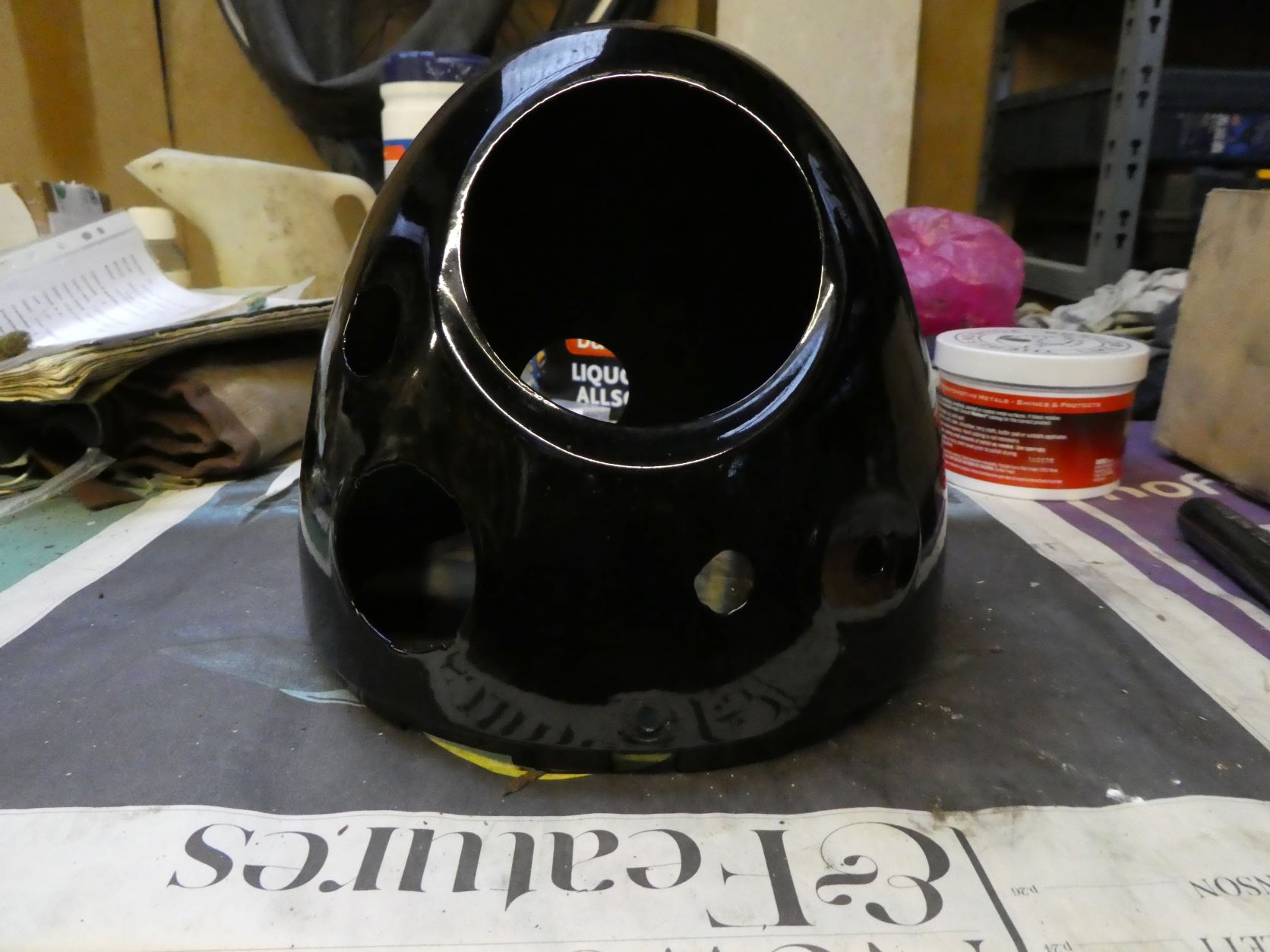
I do have the original shell with the switch on the left and ammeter on the right but this was modified in the 1970s when two extra holes were cut into the shell for an ignition key switch and small warning light. I either leave these bits in place with no function, blank them off with rubber grommets or fill the holes and repaint. I would rather keep the holes filled with functional switches /lights if possible but if not may have to go down the repainting route.
I have attached some photos of the shell
- Log in to post comments
Wiring a relay
Allan - relays are quite simple devices that use a "trigger" voltage to switch another voltage. They can be arranged to that when a voltage is applied the secondary circuit is closed, or, for your purposes, opened. You need a changeover type relay. This site has a good explanation: https://www.12voltplanet.co.uk/relay-guide.html
The terminals on the common relays available from accessory shops etc are marked as follows:
85 and 86 for the trigger (one to your ignition switch, the other to earth), 30 to the kill switch connector on the magneto, and 87a (only present on changeover type relays) to earth. So when you switch the ignition on the relay will open thus allowing the magneto to spark. When switched off the relay will close thus earthing the mag and stopping sparking.
- Log in to post comments
Ian Thanks. You make it…
Ian
Thanks. You make it sound very simple. I will study the link you have provided and hopefully it will make a lot more sense.
- Log in to post comments
Ian Thanks again for your…
Ian
Thanks again for your helpful comments and article link. After studying this am I correct in thinking that for an ignition switch function as a Magneto Kill the connections on a changeover relay are 85 to ignition key, 86 and 87a to earth, 30 to magneto kill contact with 87 being left blank. Can I also connect up a handle bar kill button in parallel with the wire from the magneto with a take off before the relay for the button to also kill the magneto. I am OK at putting things together but am a bit unsure of the mechanics of relays and it would be good to have this plan confirmed.
- Log in to post comments
Yes,
that sounds right. As with all electrics it's as well to check carefully with a multimeter that everything works as intended.
Yes you could put a kill button either piggybacking on terminal 30 or direct from the mag contact - obviously earthing through the bars although with grease in the steering head bearings this isn't always perfect. I usually have a dedicated earth wire from under something like the air lever clamp so that I know the horn etc will work.
I find relays are a simple solution to many problems which are often overcomplicated by people. For instance I had an indicator warning buzzer on one of my modern bikes that used a relay triggerd by the stop lamp feed to silence it when I had the brakes on such as at traffic lights.
- Log in to post comments
Checking with a multi-meter?
There is a subtle problem here quite a few people thank that owning a mutimeter allows them to understand its usage and often believe what it tells them, when in fact things are NOT. Some basic instruction from books and some one who knows about these things and can teach is what you need. Owning a multimeter is NOT any answer.
- Log in to post comments
Ignition key switch
The key is rather large but I fitted a stainless bracket, forward of the top fork centre nut.
I can send a photo if you wish.
BTW, thanks to much help from Jon and John, I wonder where I can buy a suitable relay to help my electronic tacho work properly on my Dommy Racer. Another problem thrown up by using a mag. (The pulse comes from one plug)
- Log in to post comments
Al:
Using a multimeter to detect whether a voltage is present or not or checking continuity is hardly rocket science. Having said that I remember chasing down a subtle fault where the meter showed I had 12 volts which was some sort of back feed via an LED.
I think I do know how to use a meter having done a technical apprenticeship with the CEGB and spent months in electrical and instrument fitters' workshops learning that amongst other things. Admittedly that was a long time ago and well before digital meters.
- Log in to post comments
The main benefit of the…
The main benefit of the Power Box is that it has a big capacitor so you can run coil ignition without a battery, or (if you disconnect the battery first) you can start the bike with a flat battery. But since you now have the magneto, won't one of Al's regulators do all you need?
- Log in to post comments
David Thanks for your…
David
Thanks for your comments. My main reason for wanting a Powerbox is, having decided to convert to 12v, is to combine rectifier and Zener diode functions into a single unit. I am sure that one of Al's boxes would do the job but , as I have indicated in some of my posts above my headlamp shell has been modified to take a separate Lucas ignition Key and a warning light. Rather than blocking off the holes that these have made in my shell I wanted to use the parts hence my wish to use the ignition as a magneto kill and the light as a charging lamp. The Boyer powerbox is available with a built in charging circuit. Al does one of these but it is an additional unit to his box that I would need to attach or hide somewhere and I am trying to keep things simple.
- Log in to post comments
Meters....
Hi Jacking this post to talk about multimeters...Yes Ian you might know a bit, but a lot of people believe they do but don't understand. The cheap digital multi meter will show a 'rubbish' display when trying to measure the Battery charge voltage (engine running) ignition interference! Then there is measuring 12V on ALL connections on a headlamp bulb, as the earth is open circuit. We have a charge fault-new battery! I have been told. I have seen new batteries filled with distilled water only, and even reverse charged by the supplier. So watch word with faults, believe nothing check several times different ways. Try to understand what you are trying to do. Electricity easy stuff-you put put it into one end of the wire-it comes out the other end! Often very quickly!
- Log in to post comments
I do agree..
... and use an old analogue meter for relevant tasks. I suppose the digital one is a bit like the cheap digital calipers - it's easy to use and readily readable unlike an analogue meter or micrometer. But all have their place.
- Log in to post comments
Zener diode function?
Yes the BB power box regulates the alternator output to 14.5V (ish) but not through a Zener diode system. Regulator/rectifiers use controlled rectifiers, that produce the 14.5 more accurately and differently to the Zener principle. The aoservices Charge Lamp control unit is a small 3/4" device that tie wraps inside the head lamp. 3 wires to connect. Both the ao Charge Lamp and the BB Charge Lamp need an 'ignition' switch to switch the lamp off when not in use.
- Log in to post comments


You cannot use the ignition switch as a Mag kill switch. They work the 'wrong way'. I do do a Magneto ignition switch, but it needs a 19mm hole. The light is up to you. I also do a charge warning light device that could control a lamp. see AOSERVICES.CO.UK