
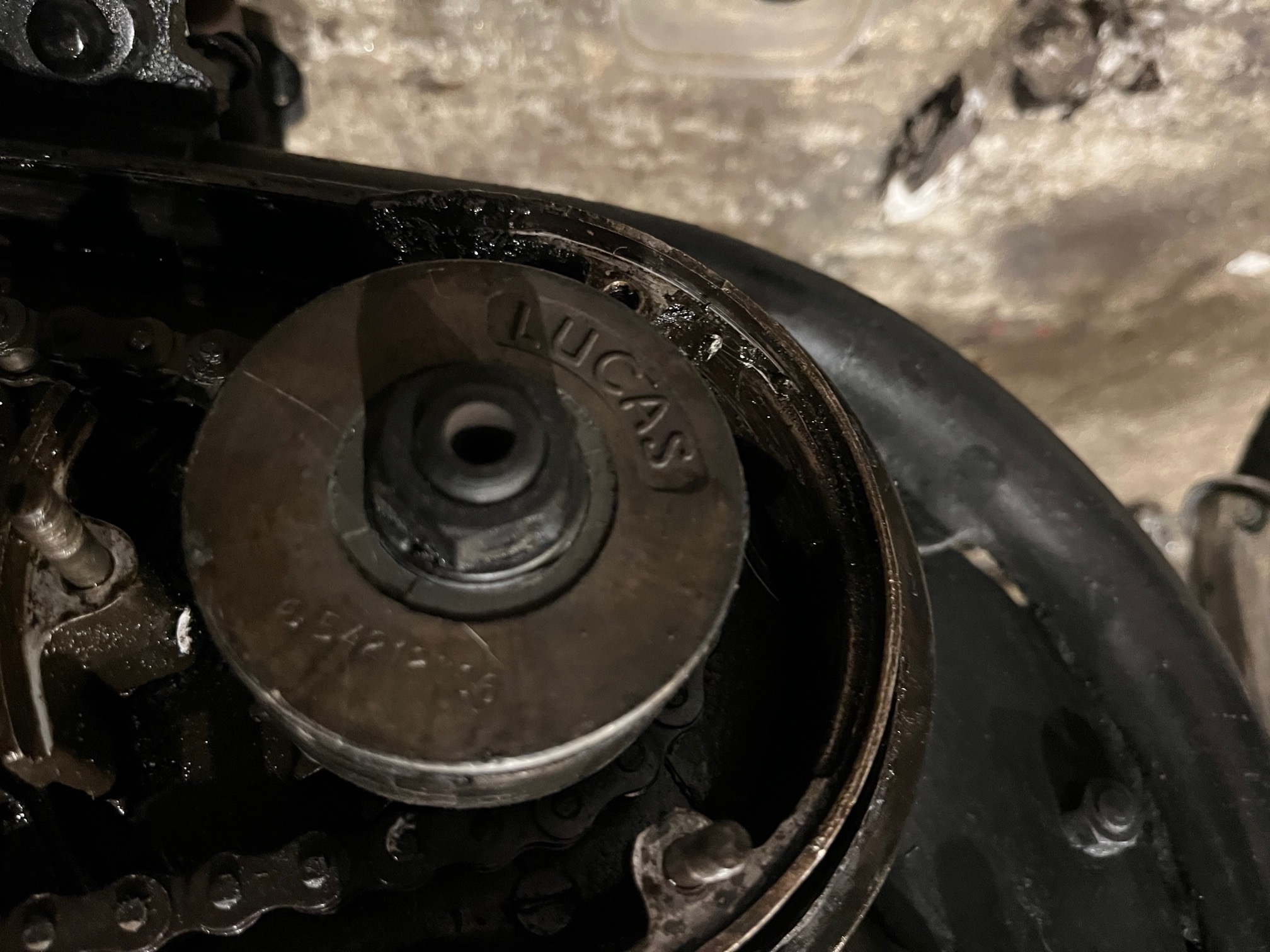
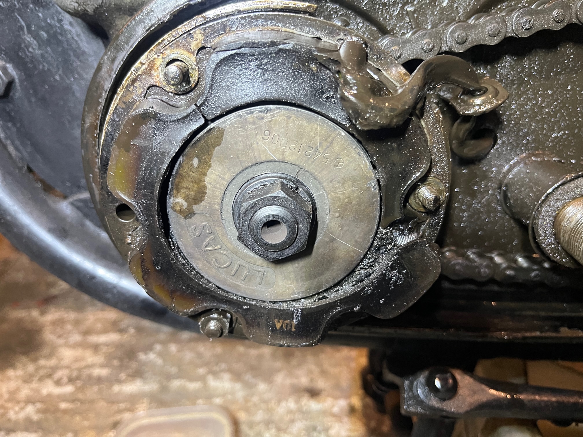
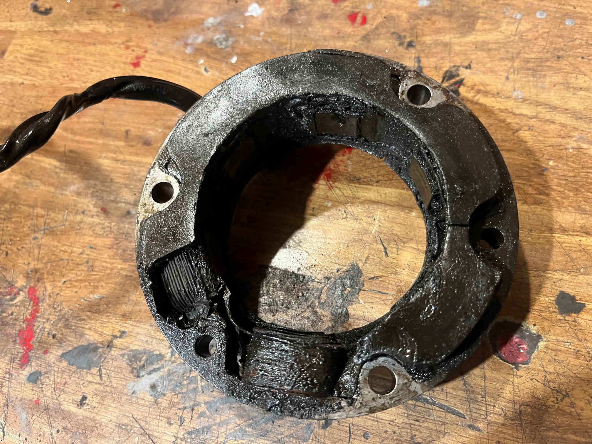
The rotor on my Atlas has decided to give up the ghost by the looks of it. Pity I can't post a video on here which shows exactly what's occurring so I'll have to explain in words and a few pics. In essence, the rotor has about 5mm play when rocking it back and forth on the shaft. It looks like the central metal part that slides onto the shaft/woodruff key is coming away from the larger magnet part. That play and slight wobbling on the shaft has obviously caused it to connect with the stator, so the stator is a goner too. I discovered all this when the charging system started to go wrong.
Getting a new stator isn't too much of a problem but neither RGM or NOC shop stock the rotors, so I'm asking if anyone happens to have a spare rotor that works that I could have off them? For that matter, a rotor and stator, if poss?
The centre coming loose....
- Log in to post comments
Working on a 750 motor (…
Working on a 750 motor ( p11 Ranger possibly) I had to go through 4 used rotors till i found one the fitted the shaft nicely and felt right. You may need to get a new key or even an oversize key and fettle it to achieve a play free assembly . The so called "welded" rotors are not actually welded but of an improved design. Might be best to buy rotor and stator from the same source. Some new stators come with oversize holes for mounting ,so some form of stepped studs or sleeving will be needed.
- Log in to post comments
Genuine Lucas????
Lucas stopped manufacture in the mid 1980s The name is still being used by the Wassell empire on goods made in the far east.
The 54212006 rotor we have here was the original part number (and is the one that comes apart) was used throughout the 1970s on the commando etc.the later part that replaced it was 54202298. These are both Lucas numbers from the 1980s so how relevant to the 'modern part' now sourced from the far east, that is any ones guess. We watch with interest.
- Log in to post comments
Roger mentioned sleeving the…
Roger mentioned sleeving the larger stators, please consider the advantage these holes will offer by allowing more wriggle room to achieve a rotor stator clearance of .008" minimum.
- Log in to post comments
I bought a new rotor from…
I bought a new rotor from Rex's Speedshop (which luckily is only 30 mins drive away from me) Really nice helpful guys they are too. It slid on the crank shaft nice and tight.
A friend gave me a used stator that appears to be in good condition and he said was a good 'un. For my own peace of mind I got Luke at Rex's Speedshop to test it and it passed no probs. Trouble is, when its bolted on I just can't get a minimum air gap of 0.008" all the way round. There's always ONE segment that the feeler gauge wont slide into and it's always in the same spot even when I turn the crank.
I noticed there's a very tiny amount of play between the studs and the stator holes once it's been slid onto them, so I inserted THREE feeler gauges and slid the stator on over the rotor, tightened up the three bolts then removed the feeler gauges, but the problem persists. One segment is always less than 0.008".
I've checked the crankshaft runout. It's true as a die, as is the rotor when it's bolted on, so I can rule out crank bend.
No matter how many times I try I just can't seem to get a clean gap air all the way round. I can only summize that the internal diameter of the used stator must be slightly warped, though I can't see any fluctuations when using a Vernier gauge.
Tomorrow I'll go get a new stator from Rex's Speedshop and see if that solves the problem. If I can't get a decent airgap after doing that I guess I'll have to investigate if the stator studs are bent.
Also, the three stator nuts are supposed to be tightened up to 15lb ft (20.3 NM) per the Haynes manual, but it feels like they're going to shear off if I go that much, so I backed off on waiting for the torque wrench to click fearing I'll damage the studs.
Hopefully, a new stator will do the trick. (Famous last words!)
- Log in to post comments
I've quoted Norman Whites…
I've quoted Norman Whites suggestion before on this site but I see it could be of use here.
Norman suggests that the stator bolts be machined down to the core diameter of the threads to enable a tad more clearance to be obtained around the rotor.
15ft lbs is the figure quoted in my Routine Maintenance manual.
If the bolts snap they are not of the correct material or are fatigued.
- Log in to post comments
Interesting idea. I'm not a…
Interesting idea. I'm not a metallurgist but wouldn't machining down the thickness of the stator bolts weaken thier tensile strength and require that the lb/ft torque needed to tighten them be reduced? (i.e. less metal, thinner stud, more stretch) I might be talking b******s but that kind of makes sense doesn't it?
These studs do look a bit fatigued to be honest. I can almost 'hear' them stretching as I tighten the nuts up, and the bottom one is a bolt/stud as it's been wound out of the base, not that that should really matter.
I'll try the new stator tomorrow and if that doesn't sort the air gap out I'll concentrate on the studs
- Log in to post comments
The most usual method to get…
The most usual method to get the gap to equalise is to give the offending studs a "bump" ! in the required direction. But i did not tell you that !.
- Log in to post comments
Air gap spacer
Hitchcocks sell a laminated plastic strip that is the right length to go round the rotor and the thickness to give the requisite air gap apparently.
insert, tighten the stator nuts, remove - voila (in theory).
For Doris, I packed the gap with old broken feeler gauges at the stator fixing points and tightened as you did, which did the trick.
Good luck with it Graham.
- Log in to post comments
When I spent quite a while…
When I spent quite a while in the hydraulics repair industry tie rods invariably came with the main length the same core diameter as the threaded ends.
Sizes could have been from 5mm O/D to and beyond 32mm in my experience.
These tie rods/bars had to contain anything from 100psi to 4,000 psi.
I only ever had one malfunction from a 16mm tie bar when the nuts were forced off along the threads under 250 bar pressure! 16mm tie bars would have a core diameter of circa 14mm as an example.
- Log in to post comments
I suppose it's always going…
I suppose it's always going to be a bit touch and go fitting a used stator. Who really knows what punishment it's endured even if it does test well and look relatively ok. If a brand new one doesn't fix the air gap problem it can only be the studs or summat up with the base plate that the stator bolts to. It may be slight skew-wiff by just a touch. I really hope not.
- Log in to post comments
To understand the working of…
To understand the working of this phenomena consider this if you will. The thread is only there to keep things together the main strength is from the core diameter of the whole system which will be constant along the length.
- Log in to post comments
The tolerances of newly…
The tolerances of newly produced rotors and stators are much finer than the originals, so out of the box, the air gap is less.
In my opinion, it’s not enough.
I don’t like the idea of waisting the alternator studs or hogging out the holes in the stator, so I take a light skim of the rotor in the lathe.
https://youtube.com/shorts/OULRRNfaRpE
I aim for a 12 thou air gap rather than the 8 to 10 that the factory workshop manual calls for.
It’s peace of mind for me, and after lot’s of testing over many years on several engines, I have seen no less power output, which is why I’m comfortable sharing this recommendation with others.
- Log in to post comments
Grant, I too would like to…
Grant, I too would like to see a slightly bigger air gap but I haven't got a lathe and I've now got the air gap to it's minimum tolerance so I'm going to go with that, though I'm definitely going to re-check it after running the engine!
- Log in to post comments
I think I've done it. …
I think I've done it.
Before I went ahead and bought a brand new stator I gave it one last try with the used stator that a friend gave me using Alan's method. I found an old aluminium head gasket in the scrap metal bin that came off a 250 GT Suzuki I was restoring, cut three strips from it, loosened the stator and slid the strips in then pushed the stator fully home, tightened up the three bolts then pulled the aluminium strips out. I then turned the crank through 360 degrees checking all the segments as I went. The 0.008" feeler gauge slid in on every one. It slid in a bit tighter in a couple of places but still, it slid in, so none of the segments are less than the minimum air gap tolerance allowed. Phew!
- Log in to post comments
Started the engine. The bike…
Started the engine. The bike is charging and the low voltage warning light is working properly again, i.e. it comes on when the ignition switch is turned on and goes off after 1500rpm
Result!
- Log in to post comments


... is a common occurrence on theearlier rotors where the magnets are just cast into the aluminium alloy. Later ones are welded to avoid the problem. It's a good job you caught yours in time!
Rex's speedshop show the welded rotor in stock: https://www.rexs-speedshop.com/product/genuine-lucas-rm20-rotor-lu54202299/