
I'm having the crankshaft of my 57 88 reground and of course I need to quote what clearance I want. This is not specified in the regrinding data of the manuals. For the larger journals I generally see people quote a figure of 0.001" for a road bike. Can someone please confirm that is or is not the same for the smaller journals (500cc/600c)?
Thanks,
James
T100 unit 500 Triumph…
- Log in to post comments
The manuals state grind…
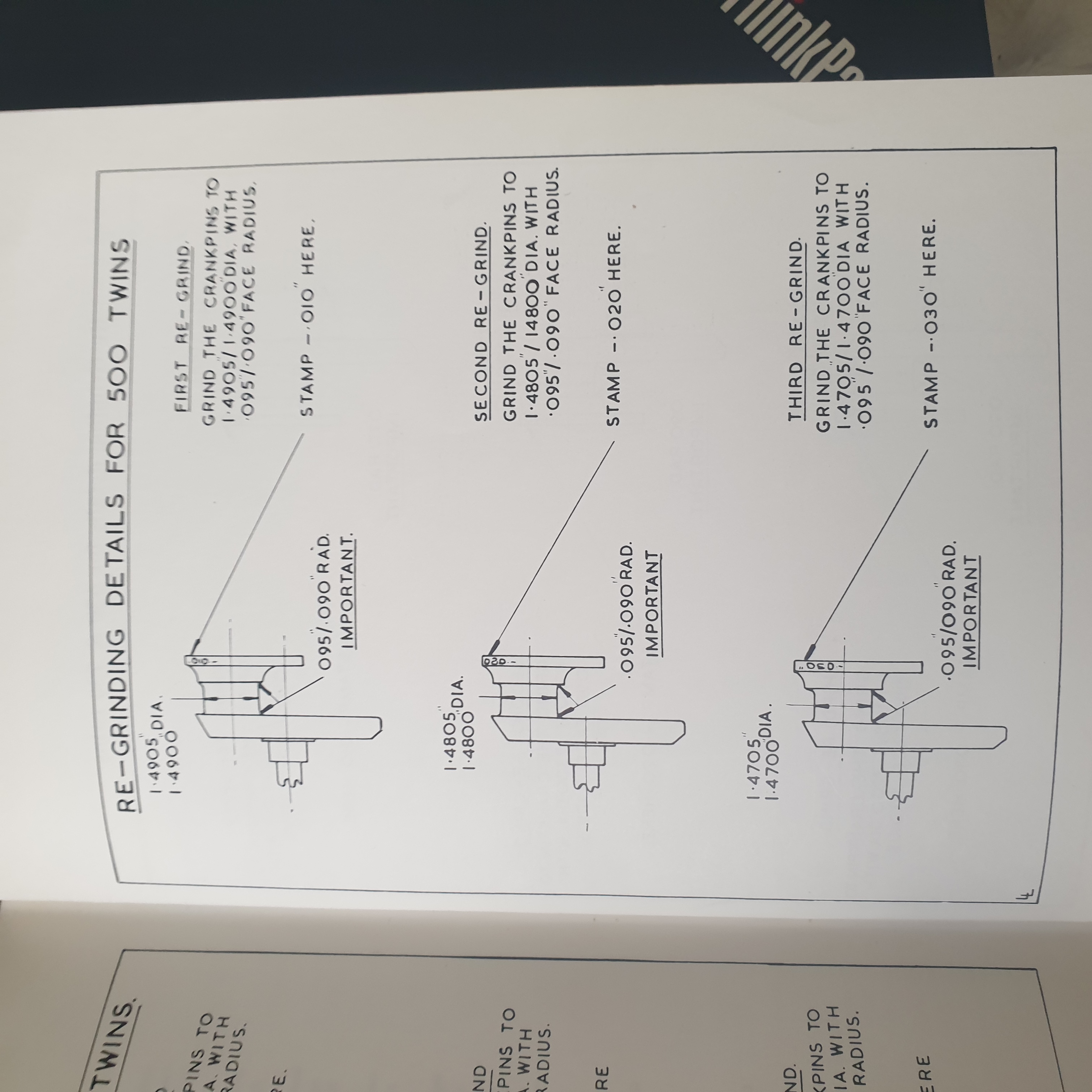
The manuals state grind sizes, 1.4905-1.4900, 1.4805-1.4800 and 1.4705-1.4700. With the vital radius 0.095-0.090. Then reassemble. How can you even measure con rod internal size to 0.0005" without the con rods being fully assembled and their bolts tight? The grinder only needs to know the journal size as the book gives it.
- Log in to post comments
The manuals state grind…
The manuals state grind sizes, 1.4905-1.4900, 1.4805-1.4800 and 1.4705-1.4700. With the vital radius 0.095-0.090.
Those are the journal sizes not the bearing to journal clearance tolerance, the .0005" journal size tolerance is easy to measure by a grinder as they have the right equipment.
After your crank is ground use plastigauge to measure the fully assembled internal shell to journal clearance. Cost is the plastigauge and 2 extra new con rod nuts.
https://plastigauge.co.uk/
- Log in to post comments
Do owners usually check…
Do owners usually check after changing bearing shells? News to me. Not that I've done it very often. Surely that is the purpose of manufacturing bearing inserts? In not very much earlier days you would need to cast white metal, ream, fit with blue, scrape etc etc until the con rod would fall under its own weight from horizontal to vertical. Before shells were used, assembly was a craft skill. That was then...not now. You wouldn't measure its clearance then or now. Have it ground properly and put it all together.
Radco (and other sources) says "under no circumstances should a renewable shell be scraped to ease off a tight fit".
- Log in to post comments
Normally you wouldn't bother…
Normally you wouldn't bother and yes the shell bearing makers are working to their own limits which they are well capable of meeting. But the shell relies on just more than the journal being to size but also the con rod inner ID being both round and to size with no burrs or swellings. After 40 to 50 years of a con rod either being used or being stored and bumped around it may be time to check. To check this you can either have expensive measuring equipment and more importantly know how to use it or buy some plastigauge which is designed for single use by people without the equipment and knowledge to use the equipment either.
- Log in to post comments
As John says its possible…
As John says its possible for the rods to go out of round ( they can stretch!) and the clearance at the point where the shells meet can close up. In my case I lost about a couple of thou. As my crank had worn a thou or two it all went together and turned freely and has now run like that for 20 years at least. I would take the rods and shells in with you to the crank guy. Try not to reverse or swap the rod positions. Mark them with a felt tip .
- Log in to post comments
I should have mentioned that…
I should have mentioned that I am taking the rods assembled with new shells and torqued to spec. So the grinder is working to the correct clearance rather than the grinding data. This has been widely recommended as the way to go. The rods will be labeled for reassembly.
- Log in to post comments
Go for 1 thou then, middle…
Go for 1 thou then, middle of the Triumph figures. It will only be 1 thou at the crown, at the part line there are reliefs for the bulging of the shell caused by the crush or overstand of the shell so the clearance is larger here. As you are bringing the assembled con rod and shell to the grinder he will be aware of that and base his clearance on the crown measurement but also check at the part line in case the overstand is causing too much bulge and possibly bind.
- Log in to post comments
Worthwhile
Marking the direction of rotation on the crank so that when it is lapped/polished (final process) it will be done in the correct direction.
Maybe teaching m/c shop to suck eggs, but better safe than sorry.
Regards, George.
PS: Don't forget to clean out the sludge trap afterwards!
- Log in to post comments
A thou total or per inch of…
A thou total or per inch of journal, ideal would be 0.00075''/0.001'' per inch of journal diameter as required by the manufacturer of the shells The shells are designed to give the correct installation clearance when the journal is ground to the manual dimensions. Why change what has worked so well for others. As john says, use plastigauge, it will tell you what you have, either in tolerance or out of tolerance in which case your grinder will have gone to far.
- Log in to post comments
Crankpin radius
I used to do metallurgy on ground Helicopter Critical parts in the seventies. The most important part is the corner radius on journals. Machine with plenty of cutting fluid, do not "burn" the radius, and no steps over 2 tenths of a thou, .090 inch radius minimun, blend in smoothly. Many a Helicopter main rotor shaft has snapped due to incorrect grinding techniques. I have seen crankshafts on Ebay that are scrap due to over grinding and sharp corners. To get someone home, I have put shims behind the shells and explained to do it properly as soon as possible. People complained the crank ran the ends after two weeks! Make sure the journal is round within half a thou and parallel within half a thou. It is a job to find someone who knows proper engineering practice these days, especially if one follows the antics of Botch it and Scarper on Youtube.
- Log in to post comments


T100 unit 500 Triumph clearance is .0005 to .0015 on a 1.45" Journal.