
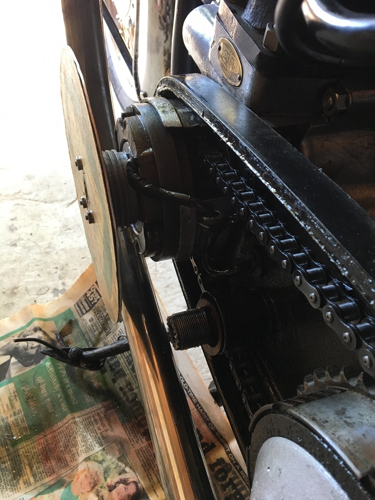
My bike has a belt drive fitted. This means that the alternator has to be spaced further out than with chain drive (bike purchased already modified) and this poses a problem with fitting a timing disc to the end of the crankshaft. I have been trying to work out away of securing the timing disk and have designed a spacer that should resolve the issue. It has to support the disk sufficiently far away from the rotor in order to clear the wire from the stator. Please see attached scan.
Two questions:
1. Has anyone else had this problem and found a solution ?
2. Can anyone make the part detailed on the attached scan. Of course I am willing to pay the going rate.
Thanks, Mike
timing disc
- Log in to post comments
Another approach
On my Manx, I had the problem just to check ignition timing with engine running at over 3500rpm. I simply made a pointer, checking at the allen screw on the sprocket. Set at TDC. Then used one of those modern strobe timing lights with digital display of advance. You can find cheaper ones than https://www.conrad.com/p/equus-5568-pro-digital-timing-light-12v-857336
- Log in to post comments
My Solution
Hi, Mike.
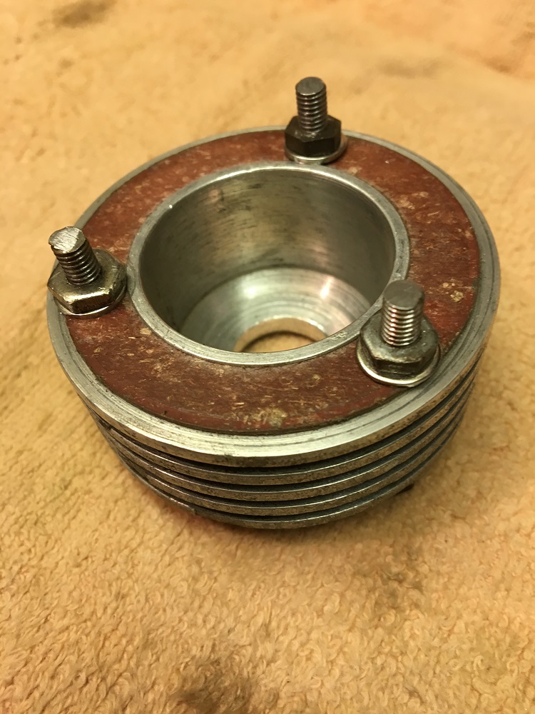
I had a similar problem with my 650SS which will be the subject of an article in a forthcoming issue of Roadholder. My solution, though it won't help you if you don't happen to have one, was to use a surplus, after market carburettor float bowl extension, drill out the middle of the bowl to attach to the crank and then affix my timing disc using the original three mounting holes. As per the attached.
- Log in to post comments
Timing disc use
Some years ago I bought a thin but stiff timing disc to time my 1961 Model 50 with points and coil..
After fiddling with it for a while I had an epiphany....
I used a small thin cutting bit in my Dremel kit and cut two short slots in it, one at TDC and the other at the proper number of degrees BTDC. I then brought the piston up to TDC on the firing stroke, then held the disc up to the end of the crankshaft over the stator.
Using a small thin paint brush I painted two lines on the stator, one at TDC and the other at the correct number of degrees BTDC for the firing point. Another line was painted on the rotor in line with the line on the stator at TDC
Using a strobe light you can easily see where the firing point is and make corrections accordingly.
It is interesting to watch the firing point advance as you bring the revs up.
Mike
- Log in to post comments
Threads
My Electrex documentation says that the mainshaft thread is 20TPI Whitworth Form on Dominators, but 20TPI UNF form on Commandos.
Neither a standard pitch for any series AFAIK, but you can get 20TPI Whitworth form taps and dies on eBay still. I did three or four months ago.
These nuts are to be torqued down to 80ft/lb, so mild steel wouldn't hack it.
The belt drive kits on offer don't really seem to deal with the very deep sleeve nuts you are going to need. I wanted to get 10 full turns on that mainshaft The tapered sprocket keyway relies in it.
A short bolt to retain the timing disc would be good.
- Log in to post comments
It's a BSC thread
Unlike Whitworth threads it has 60 degrees angle. The cycle thread has usually 26 tpi, but on larger diameters comes in both 26 and 20 tpi.
- Log in to post comments
20 TPI Thread
It was advertised as being a popular thread on classic cars of the 50s and 60s.
I think Norton engineers had a dice with CEI/BSF/UNF/Whit/BSP/BA on different sides.
Steve
- Log in to post comments
Sleeve nut
Mike take a look at eBay 222085777802 - some of the hex could me turned off to get close.
Steve
- Log in to post comments


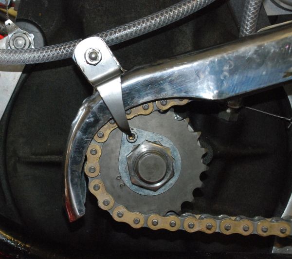
I fitted a belt a belt drive to my Atlas. In order to time it with a strobe I made up a timing disk which was smaller in diameter than the stator. I fitted this under the big nut and positioned it so that it showed TDC with the crank at TDC. I then marked the stator at 28,30, and 32 before TDC. Next I scored a groove at these points using a hack saw blade. I cleaned the area and then applied some oil based paint to the grooves and wiped the excess off.
I removed the timing disc and refitted the big sleeve nut and tightened it. I now set the timing on my atlas by removing the outer primary and proceeding in the usual way. I have a Boyer fitted and I can get the timing spot on.
Andrew