
A friend of mine (and club member) has recently bought a part finished Mk3 commando project, he's got most of the bike assembled but is having difficulties sorting out the wiring, which is about all thats left to do. It has a new loom already fitted but he is having difficulty working out which bits go where, how they connect and what connectors it should have. Is there anyone in Devon ( Hes near Dawlish) that either anyone can recommend he can take the bike to, or better still a Commando savy member that would be prepared to give him a hand and at least point him in the right direction!
Cheers
Dan
Start with the wiring diagram...
- Log in to post comments
Enter Mk3 final wiring into…
Enter Mk3 final wiring into the search box above.
Regards, Al.
- Log in to post comments
Sorry for the delay replying…
Sorry for the delay replying - thanks for your reply Al, ill see what i can do to help and come back with any specific questions.
Dan
- Log in to post comments
f there is anything non…
f there is anything non-standard about the electrical set-up, it is very possible that Grant Tiller has a modified wiring diagram for it: https://granttiller.com/
- Log in to post comments
Julian, Thanks thats a…
Julian, Thanks thats a useful resource.
Am I right in thinking that the headlight, ignition switch and warning light cluster have separate sub looms?
I think that/they are missing which isn't helping!
Dan
- Log in to post comments
Hi, It is clear from the…
 Hi, It is clear from the circuit diagram that the headlight, ignition switch and warning light cluster do have separate sub looms.
- Log in to post comments
Ok my friend .....honestly -…
Ok my friend .....honestly - I dont own a commando! Is still struggling with the wiring of his 850 electric start. It's coming to me shortly as another friend of his was unable to solve the riddle!
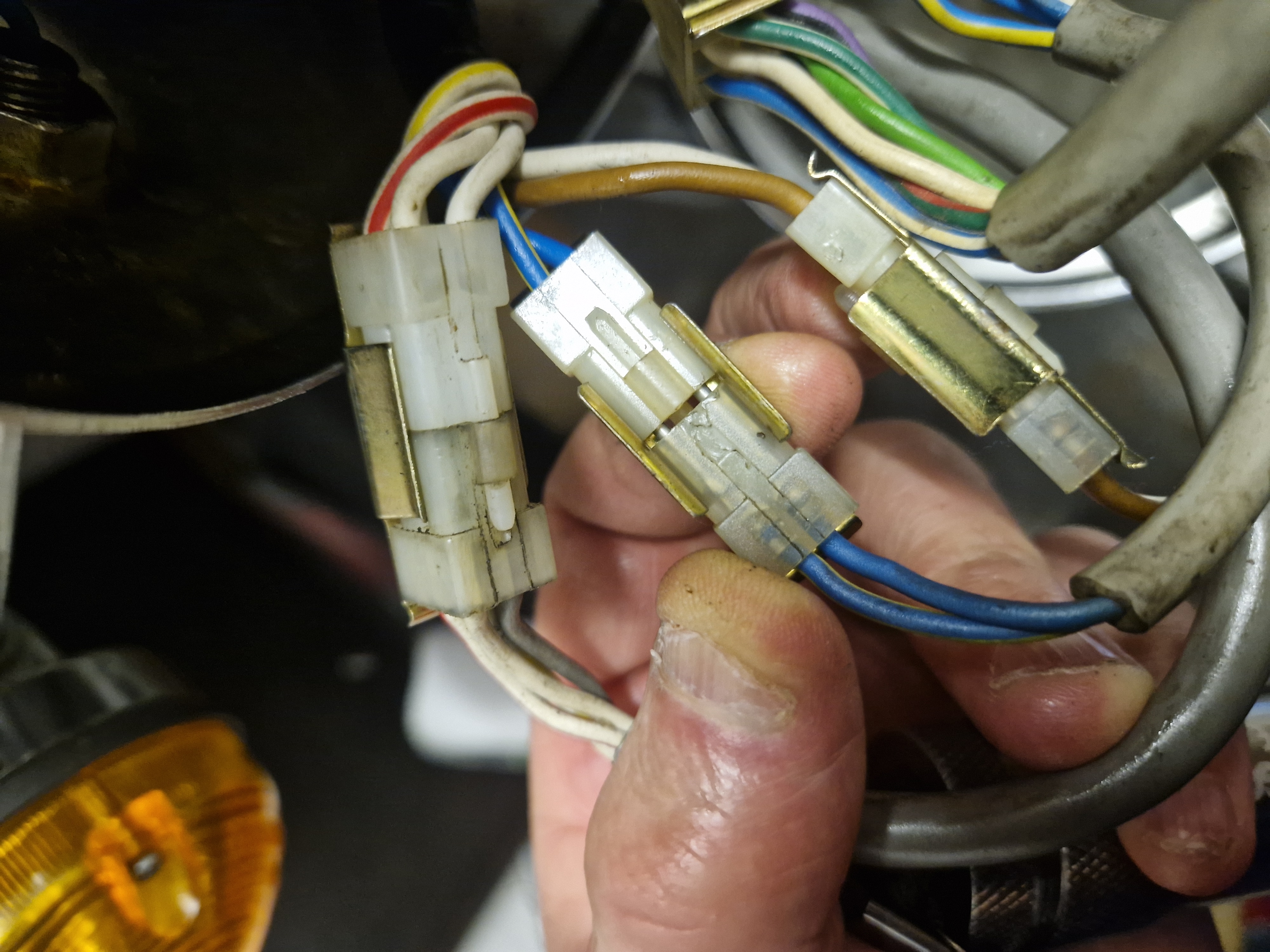
Simple question first, the wiring looms (fitted by the previous owner but not connected) seem to have a coloured thread running through them, the rear secton is black with a yellow thread, the middle bit black with a blue thread and the front section is black and yellow again. Is this of any significance? The problem seems to be with the black and blue section which has a bunch of white block connectors that don't seem to have an obvious home. But can he find anyone selling the reciprocal white connectors anywhere. I'll know more when I get the bike, but am I missing something simple here?!
- Log in to post comments
Hi Dan, Have a look at (for…
Hi Dan,
Have a look at (for example)
https://www.feked.com/genuine-lucas-main-wiring-harness-norton-commando-mk3-06-6396.html?srsltid=AfmBOopPU-xEJZwqWeQgnwnRrlcfb5ataplt7BIaURz38kD1DYOBbR7M
And you will see a picture of the main harness with yellow thread.
and
https://www.feked.com/genuine-lucas-headlamp-wiring-harness-norton-commando-mk3-1975-06-6438.html
For a picture of the headlamp harness.
The colours of the wires will be as per the circuit diagram.
Other sub harnesses are available but you get the idea.
You should be able to look at wire colours and tie them up with the circuit diagram.
By the way, I have never found anywhere where you can buy the white connectors. Obviously they are available as the looms have them. Anyone know of a supplier?
- Log in to post comments
Thanks,Ive just received the…
Thanks,Ive just received the bike and will post some pictures soon. I think part of the problem is that the main harness has another harness connected but is not right, (the blue threaded one) I also have a headlight and ignition harness that does seem to be right!
I was just looking through the Access Norton site and found this link for connectors https://tricor-andy.com/product/4-pin-connector/. They do others!
Dan
- Log in to post comments
No wonder it was confusing …
No wonder it was confusing .... there were two headlight harnesses connected to each other`!! having removed the offending item I have now been able to identify all the major wires, my only questions now are of a more practical nature, there are 3 wires coming from the stator but only 2 connectors on the Lucas loom, if I've understood it correctly, I'm assuming its a three phase and will need to work out how to connect it to a regulator rectifier - but its progess - any advice greatly received, I'm more familiar with 1950's dynamo singles!
Dan
- Log in to post comments
3 Phase (or not)
Firstly ascertain if you have a 3 phase stator? Does it have 9 pole pieces? (6 poles pieces is single phase)
The original MKIII system will have 3 wire connections to the two alternator connections, ie the original rectifier, the two Zeners on the AC side of the rectifier and the 2 to the Ignition Warning Light unit. (4 connections in total)
I suggest these 2 off triple wires are 'removed' or 'made safe' and not used.
Install 3 off new wires (YLW) from your new stator to the regulator rectifier. And redirect the Ignition Warning Light unit to two of these stator wires. Unless you are cancelling that system and fitting a BSM, which works on the DC side of things.
- Log in to post comments
Sourcing White Connectors
Att'n Tony Ripley
Tony, are you able to confirm whether these Tricour connectors that Dan mentions are indeed the correct ones?
Or can anyone else for that matter? Anyone used them, and are they well made?
Cheers.
- Log in to post comments
James, The replacement block…
James,
The replacement block connectors aren`t great, they are small and tricky to connect pins to wires. I would recommend removing them and using original type bullets or modern equivalent which will also cause less space issues under the tank.
The blue and yellow flecking on the harness sleeving has no significance I believe, presumably they are manufactured by two different companies, even if supplied by the same distributor (Wassell) who don`t seem to be able to get the original specification right ie plastic sleeving.
I have incorporated the earlier warning lights into a Mk3 console and fitted a BMS in the ignition light housing as you mention but it`s hard to see with the red lens so a clear lens is needed if anyone knows of a source?
Regards, Al H
- Log in to post comments
Clear Warning Lamps
Appreciated Alan.
I understand that the earlier lamps are "jewel" types rather smooth as on the original MK3, and think I read somewhere that the clear ones are also available from Wassell?
Did you have to cut them down in order to leave enough clearance below when fitted? I know that this is required with some, but don't know who the manufacturer was.
- Log in to post comments
Hi James, They certainly…
Hi James,
They certainly look the same but I have never bought any.
As to are they well made, they look just as well made as the original ones, take that any way you wish. I have replaced the lot on my bike.
Tony
- Log in to post comments
Connectors for the Harness
Thanks Tony,
Looks like I'll probably be grouping them under the same heading as the MK3 neutral warning lamp switch, console warning lamps, ignition switch, and the indicators.
Sounds like there could even be a niche business opportunity for someone?
Lets see what Dan makes of them. I wonder if a new male connector half will mate properly with an original female, and vice versa?
- Log in to post comments
Hi Al, I haven't had a look…
Hi Al, I haven't had a look at the stator yet, the cover is on and I'm away at the moment, I will have a look when I get back. But thank you for the advice. Im not sure what Kerry wants to do about the charge light but I would probably suggest a BSM. I'll report back when I know some more.
James, Ive ordered some connectors - Ill keep you posted!
Dan
- Log in to post comments
Warning Lamps
Cheers Dan,and love the bike! Is that a side panel from an Indian Velocette that I can see?
It's a great shame that the BSM warning light lens doesn't match a much needed upgrade to the factory MK3 warning lamps on the console (which are fragile and a pain). I guess they were originally relatively cheap in '74, and my, don't they look it when removed.
I understand that the earlier Commando headlight shell warning lenses can be easily substituted, and I'm wondering if the BSM charging light lens could be reliably incorporated into a transparent earlier lens, in the space currently occupied by the assimilator lamp?
- Log in to post comments
James - it's a Rickman…
James - it's a Rickman Metisse with a shortstroke 500 engine, built by Mike Pemberton - I race it at Classic scrambles, it's looks get more appreciation than my racing skills! It's great fun to ride!
Dan
- Log in to post comments
Ok I'm making progress, but…
Ok I'm making progress, but have a few, hopefully simple, questions !
Why are the wires from the handlebar switches so long?! I'll have to coil them into the headlight! - does the branching of the lighting harness sit inside or outside the headlight? That would make more room.
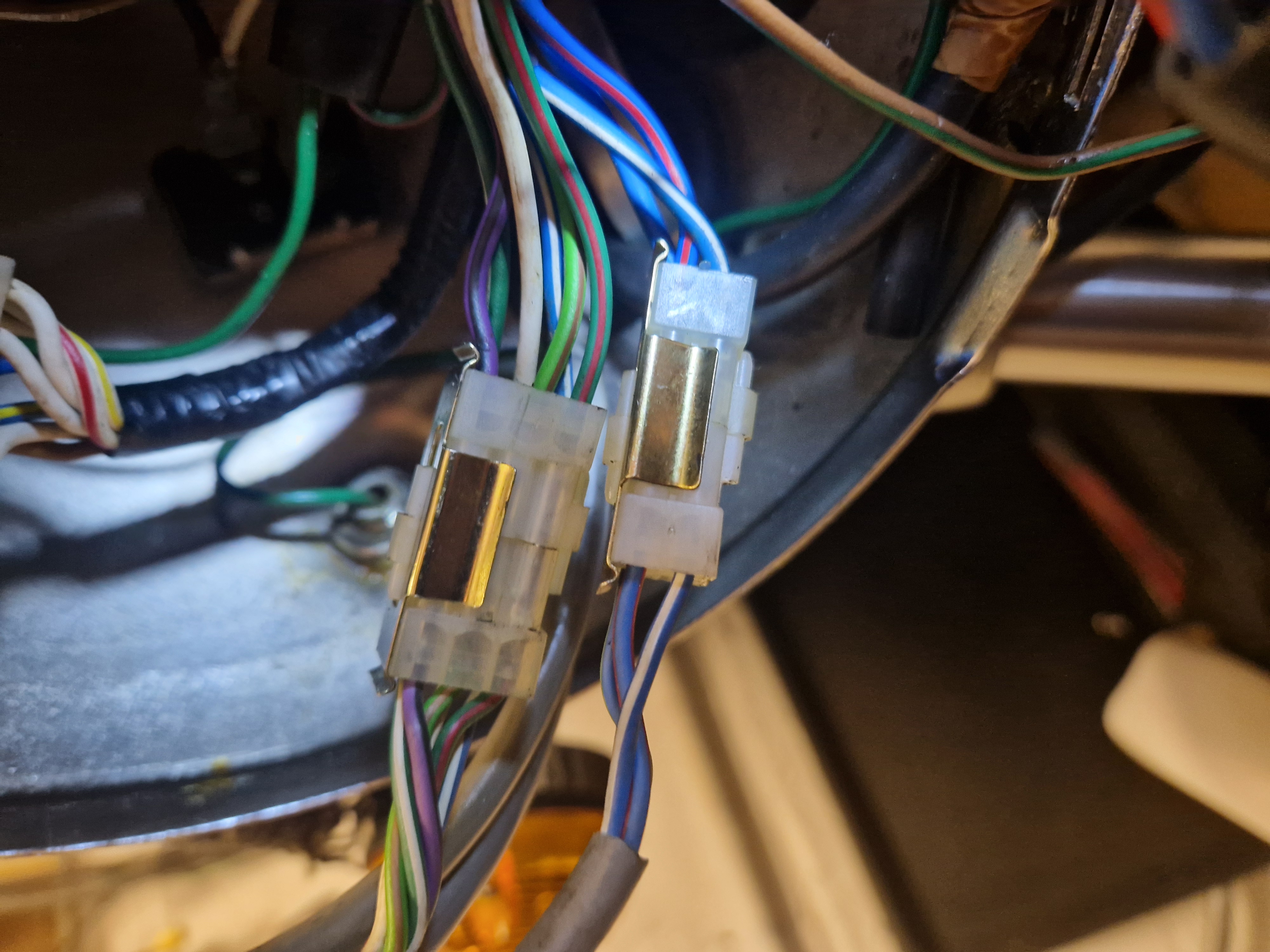
The rhs handle bar switches have 2 grey cable bunches coming from them, one with 2 ( Blue and Blue and yellow) wires that appears to be kill the switch? but I can't seem to get any connectivity from the other three, which should be the starter button and main/pilot light switch? - to complicate matters the connector in the lighting harness it connects to wants 4 wires to connect -
I'll post some pics tomorrow.
dan
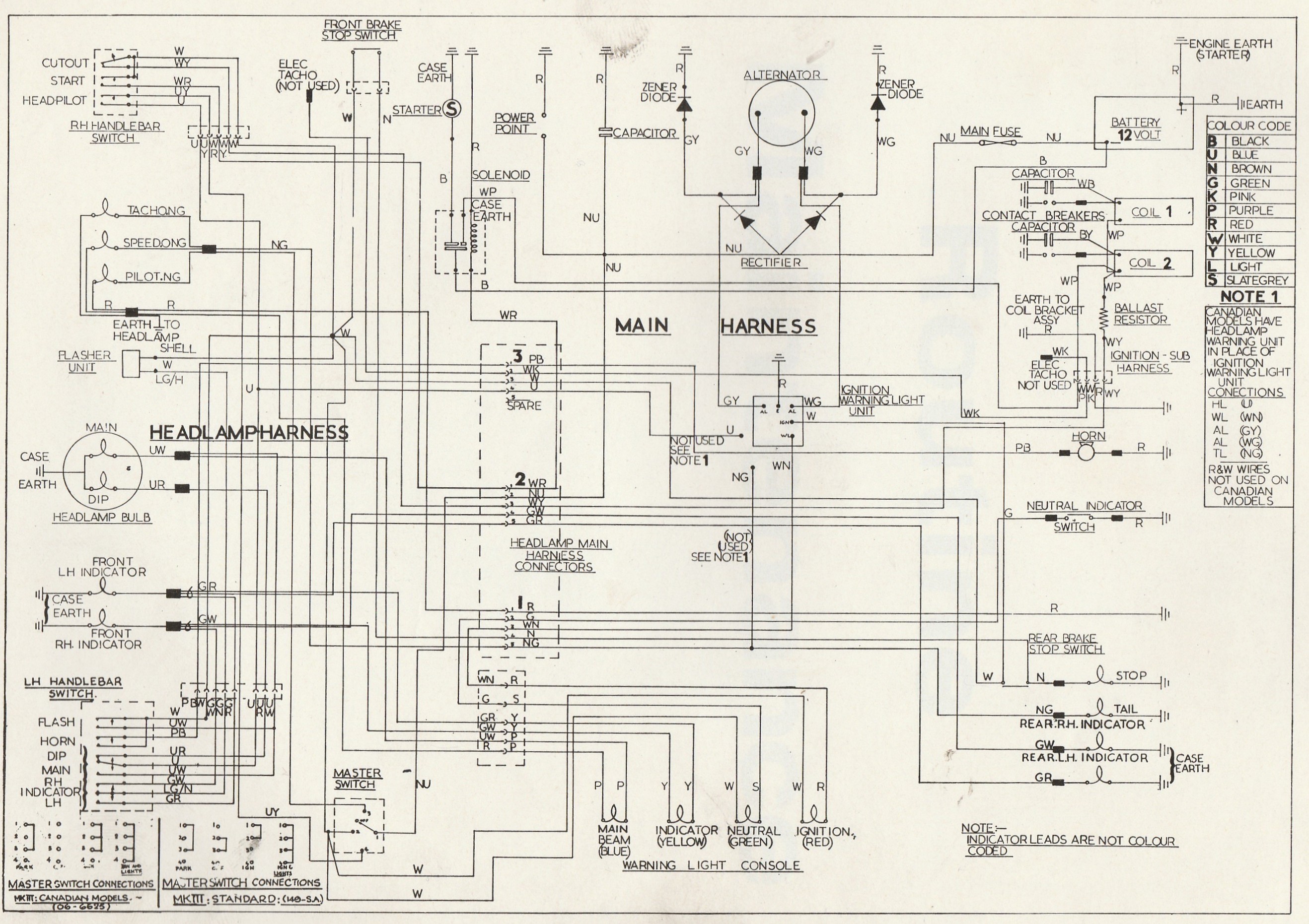
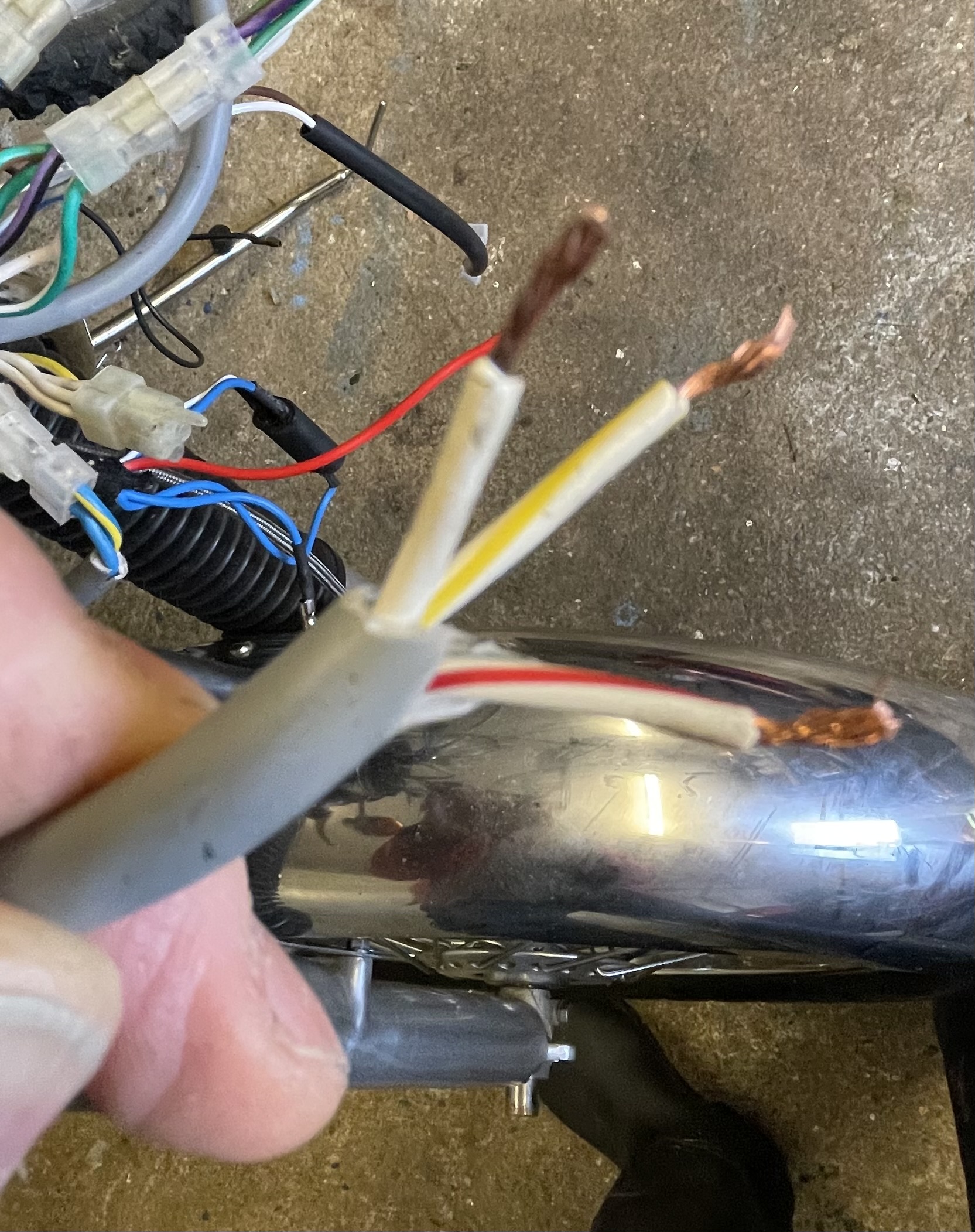
this is the 3 core cable from the RH Switch - White, Red and White and Yellow and white .
- Log in to post comments
That's is the 4 pin…
That's is the 4 pin connector they should plug in to, which has 2 white wires, one white and red and a white and yellow.
- Log in to post comments
Follow the diagram.
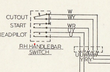
The colours in the handlebar cable are 'standard' meaning as per- WHT is ignition on (via ignition switch) WHT/YLW is ignition on (in this case after ignition kill/cut out switch) WHT/RED is start to solenoid.
Bear in mind this bike is over 50 yrs old, had several owners, and IF wiring has been fiddled with and any rewiring done 'casual' then the results will be 'casual'. Unfortunately the 3 WHT in the one connector are NON STD so we can only guess where they go.
- Log in to post comments
Thanks ALThis is a "lucas"…
Thanks AL
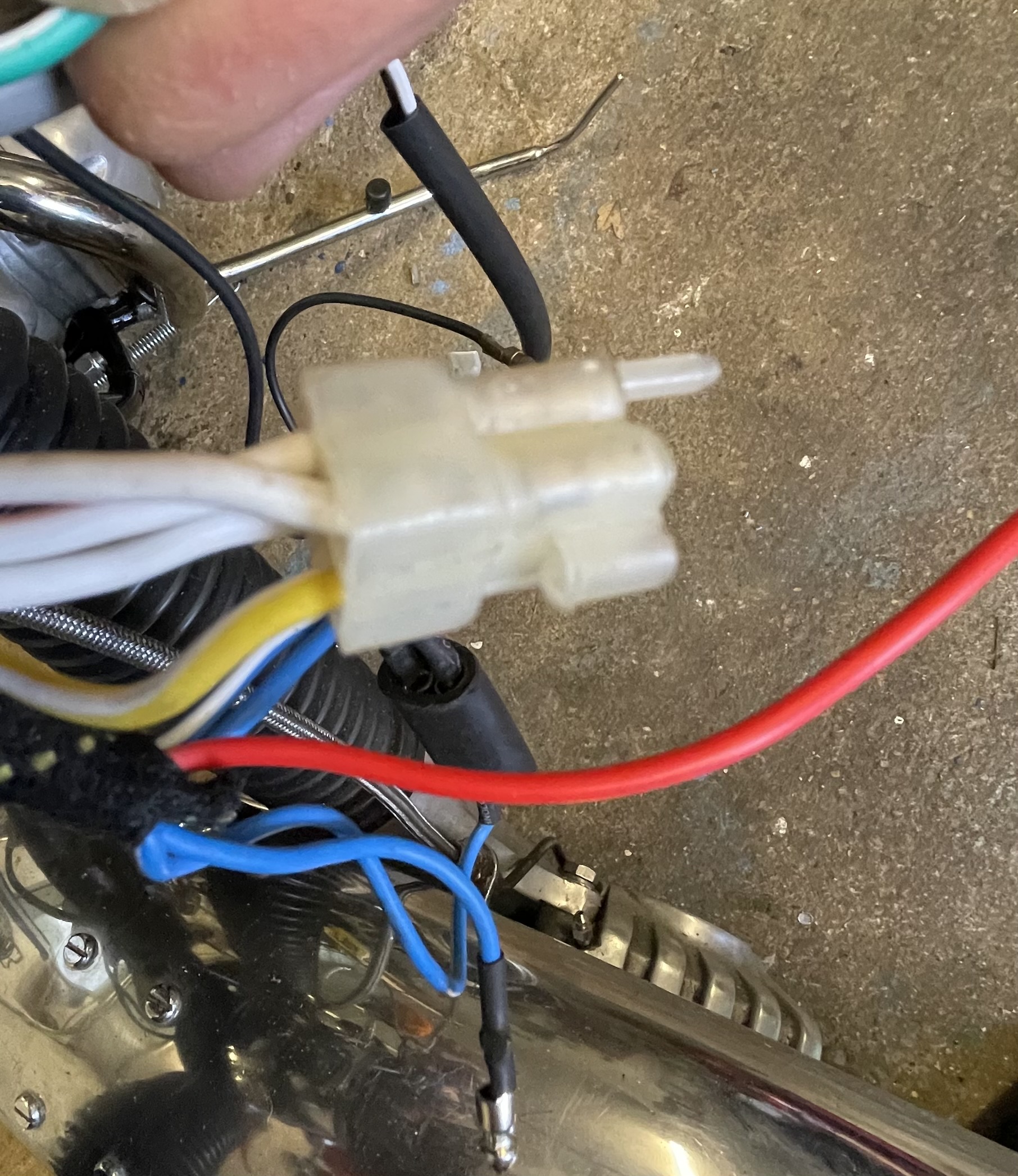
This is a "lucas" wiring loom. The pic isn't very clear, but there are two whites going to one pin and one one going to the other.
This is how it is shown in the schematic drawing that comes with the loom. You can see the white wires going into 2 pins, the loom that club sell has the same configuration. So my question remains, how do i connect the white cables!
- Log in to post comments
OK, what I am guessing, from…
OK, what I am guessing, from what you have and what the circuit diagram shows.
Is instead of 5 wires coming away, you have a 4 way plus a 2 way.
The two way is for the head / pilot and the 4 way is for cutout and start.
The white wire in the circuit digram is shown as connecting the single power (white) to Cutout and Start internally. But it actually has two separate feeds. So basically just connect the white wires of the 3 core to either of the whites on the 4 core, and it will all work.
- Log in to post comments
5 connectors
Hi Dan.
Not sure if this helps but here is a picture of the five connectors in my headlamp, it's still a standard harness.
Graham
- Log in to post comments
Tony Thanks! Graham That's…
Tony
Thanks!
Graham
That's interesting you have a grey cable, and after a bit more digging I found this on Grant Tiller's web site
"If there is a gray cable there, leave it as it is at the switch, and simply join it to the white cable.
The concern originally was that too much current could be pulled through the single white cable, so for the Commando they specced the gray to run alongside the white specifically for the starter buttonn.
However, this was proved not to be an issue on the Triumph, so was later dropped."
So that prob explains it!
Dan
- Log in to post comments
Ok Thank you for your help…
Ok Thank you for your help so far!! I've been scouring the previous threads and Grants website on this subject and have most of the loom labelled and connected up but still have some questions!
By way of reminder this isn't my bike, I'm trying to help a friend with a Commando he bought as part completed restoration. It has a Lucas MK3 loom and Boyer ignition fitted. It has also came with a regulator rectifier and an ignition amplifier. But also has an original style rectifier and one zener attached to the LHS footrest plate.
So the next questions!
I intend to fit the Reg Rectifier do I connect it to the stator and battery directly or do I connect it where the original rectifier was connected. Assuming I can/should remove the Zeners do I just disconnect them and do I have to connect any of the wires together?
Where do people fit a reg rectifier?
I assume when using the Boyer ignition an ignition amplifier is redundant?
Do I need to use the Ballast resistors that are also in the box?!
Ps I dont have the charging warning light Assimilator and will use a more modern replacement.
Cheers
Dan
- Log in to post comments
As you have been looking on…
As you have been looking on the most excellent Grant Tiller web site, I presume you found:-
https://granttiller.com/wp-content/uploads/2025/02/1975-Norton-MK3-Commando-Wiring-Schematic-Boyer-ignition-AND-reg_rec.pdf
This should answer all your questions.
Remove the zeners and any associated wiring.
Fit the reg rect wherever is convenient, but unsure somewhere that will get a bit of airflow.
You do not need the amplifier.
You do not need the ballast resistors.
Do NOT use the charge warning light assimilator.
- Log in to post comments
Tony Yes I have it's…
Tony
Yes I have it's immensely helpful in general but sadly doesn't always reflect what's on this bike as I don't have a Boyer box with charge warning light and the diagrams are schematic, plus some of the colours don't match with this Lucas loom, so for example it doesn't suggest whether to swap the rectifier with a rectifier/regulator and plug it into the loom or wire it in separately - unless I missed bit. I also can't easily see what of the redundant wiring remains live.
Had I had the opportunity I'd have made a loom from scratch instead of this over complicated ill fitting mess with too many connectors!! - Fitting electronic ignition and getting rid of the zeners, rectifier and assimilator gets rid of the need for a significant amount of wiring! But as I said - it's not my bike!
cheers Dan
- Log in to post comments
Further
But also has an original style rectifier and one zener attached to the LHS .........
If this is/was a genuine MKIII then it should have had 2 Zeners (one on each Z Plate) and the 'original style' rectifier would not be a real one but a specific one for the MKIII which is to be removed along with ALL zeners and appropriate wiring (or at least made safe) Now the Boyer Bransden ignition does have an amplifier box, but you do NOT need any ballast resistors (or condensers) all of which should be obvious from the BB fitting instructions. IN effect the regulator/rectifier replaces the original type rectifier. IE there are two stator wires, and then an earth and 'live' to feed the bike and charge the battery ie feeding the BRN/BLU that is the live feed through the bike.
- Log in to post comments
It is possible that the MK3…
It is possible that the MK3 used 3 different looms, 2 of which we know were used. The plastic Lucas connectors were used by Lucas for around a year or so before being changed by Lucas but the later replacements I have not seen on a MK3. Occasionally boxes of one half of the original MK3 connectors can be found on Ebay as NOS.
Some over think the wiring, remember at any one time try and deal with a single circuit at anyone time, it only needs a supply and return path, ie 2 cables, or one cable and earth connection. Once the idea of positive earth is understood the rest is just a methodic work through circuit (load) by circuit. if the circuit diagrams online just seem a confusing jumble then get a piece of A4 and draw out each individual circuit. And of course a digital multimeter or old AVO type devise will help immensely.
- Log in to post comments
AND
Further to Ashley-Do keep in mind the standard British wiring colours and what the colours mean, ie White (WHT) this is live when the ignition is ON. Brown/Blue (BRN/BLU) is live battery at all times. ETC
If you have power on the bike and searching for a fault where something has stopped, then a 'screwdriver' style tester (with an Earth lead/clip ) is a lot quicker and more reliable than a multimeter. You don't need to know if it is 12.9V or even 11.8V. If lamp is on you have power.
- Log in to post comments
Thanks Alan, That's helpful,…
Thanks Alan, That's helpful, do you, or anyone else?! recommend a particular indicator flasher relay or regulator rectifier for a 3 wire single phase alternator? (Ive checked - it has 6 poles)
Dan
- Log in to post comments
SO.....
....We now are getting some where, if the stator has 6 poles then it is NOT NOT 3 phase it is an original type RM19 which started life as a 6Volt charging stator and as we all know can be used on 12V. The regulator/rectifier can be any one for Single phase 12V. I sell the A Reg.
The indicator relay is NOT relevant to the reg/rectifier or alternator in any way. Any flasher relay is relevant to the indicators, and the voltage of the system, the original were 2X21W ie 42W and used A Lucas type 2 terminal flasher unit specifically for 2X21W. IF you must use LED indicators you need a specific LED (lower power) flasher unit. As it happens there are many on the market, but beware a lot are for Negative earth only as LED are often specified for Negative earth only. If in doubt get in touch.
- Log in to post comments
Simple solution - buy a new…
Simple solution - buy a new single phase stator as the one you have is not sufficient for a MK3 ES. The Tri Spark MOSFET rectifier will also suit as they are quite efficient when used with a RM23 single phase stator making the need for 3 phase stator on the MK3 pointless. You would need to make / modify the parts to get the modern version of the 3 phase stator to fit a MK3, another reason to keep it simple and and single phase.
- Log in to post comments
Ashley,Yes I'd come to that…
Ashley,
Yes I'd come to that conclusion, But as I've said this isn't my bike, but I'm talking to the owner. I don't know why the restorer would have fitted a low output stator.
My next issue with this Lucas/Wassel loom is the number of connectors to the assimulator (which I'm not fitting)
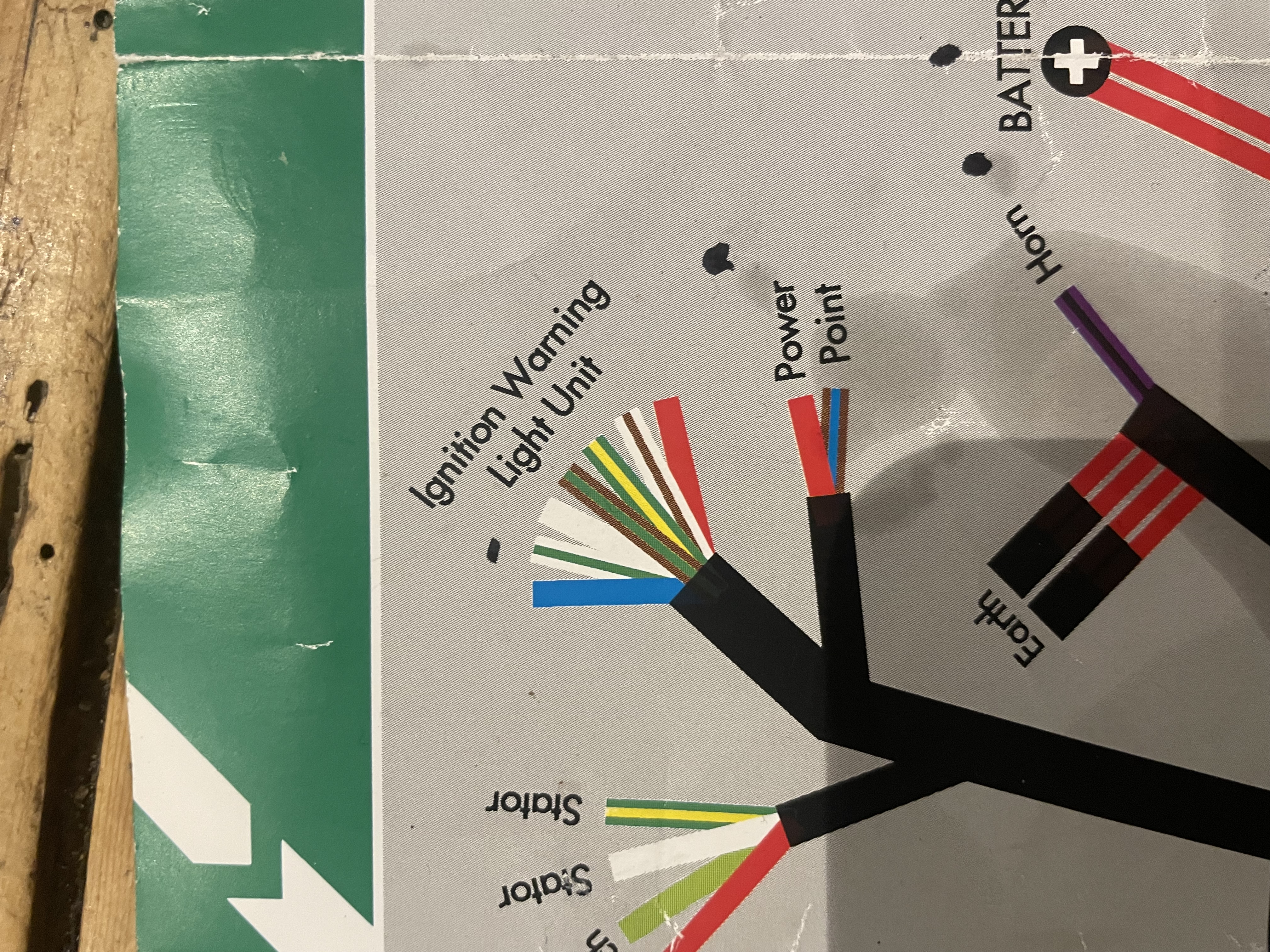
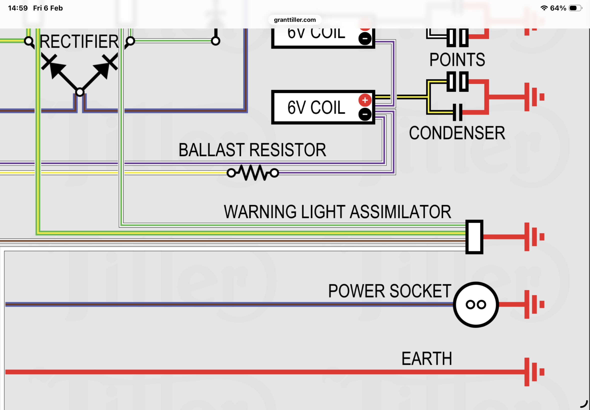
Grants schematic shows 4 connections as below, the loom as in the Lucas pic has 7. The red I assume is an earth, but what are the blue and Brown and green doing? It's out with the tester again to try and find out where they go! The Lucas pic has a blue going to the headlamp connector and green and brown going the rear lamp. I cant see those wires connecting to the assimulator on the wiring diagram?
- Log in to post comments
"why would the restorer…
"why would the restorer would have fitted a low output stator?"
'cos that's what he had lying around in a box. I'd be worried about what else he's done...
As for 3-phase versus single phase, since you're replacing all the charging system and rewiring, 3-phase costs the same and is better at re-charging the battery at low revs. Fitting to a Mk3 requires a small adjustment to the stator mounting plate, see Peter Shand's post about 2/5ths the way down here: https://www.nortonownersclub.org/forum/alternator-statorrotor-alignment
Easily done with a file and takes less than 30 minutes (don't modify the stator).
I think the Lucas picture applies to the Canadian spec. which has something to detect whether the headlight is working. Grant's diagram shows 5 connections and is right for the standard Mk3 setup, so tape up the 2 lighting wires and ignore them.
- Log in to post comments


The wiring diagram will have all the correct colours which should tie up with the loom hence connecting up will be straight forward. If you have moved any electrical items or changed any items then there is scope for confusion.
If the ignition system is changed to Electronic (which it should be) then condensers and ballast resistors are no longer needed.
If the Zener diodes are lost or considered unusable then the 'odd' original rectifier fitted to the MKIII and Zeners will be replaced by a regulator/rectifier.
IF the new loom isn't in line with the wiring diagram then of course the new loom is 'not fit for purpose'.