
My new build Dommie racer is fitted with a refurbished mag.
I have fitted a new Smiths electronic taco.
I was advised to also purchase a device to smooth out the pulses due to running via a mag instead of coil.
Two questions have emerged:
1) Where should I clip the device attachment on one of the HT's, eg, nearer to the plug or mag?
2) The lead is very long. Can I cut it or leave it coiled inside the headlamp?
Any other good ideas welcome.
Instructions are in…
- Log in to post comments
Cheers, John.
It came from the same business as the clock. (So I may have to ask them)
I'll have a go with it this aft but not cut the wire and position the sensor between plug and mag = distance. (Unless anyone thinks different.)
Thanks...
- Log in to post comments
Smoothing out? (Dross warning.)
Smoothing out may have been the wrong word.
In short: Electronic rev counter not showing engine speed when running. Needle not moving.
I have an ignition switch fitted for security and the the needle goes round and back when switched on.
Anyone used a Smiths electronic rev counter in conjunction with a mag?
- Log in to post comments
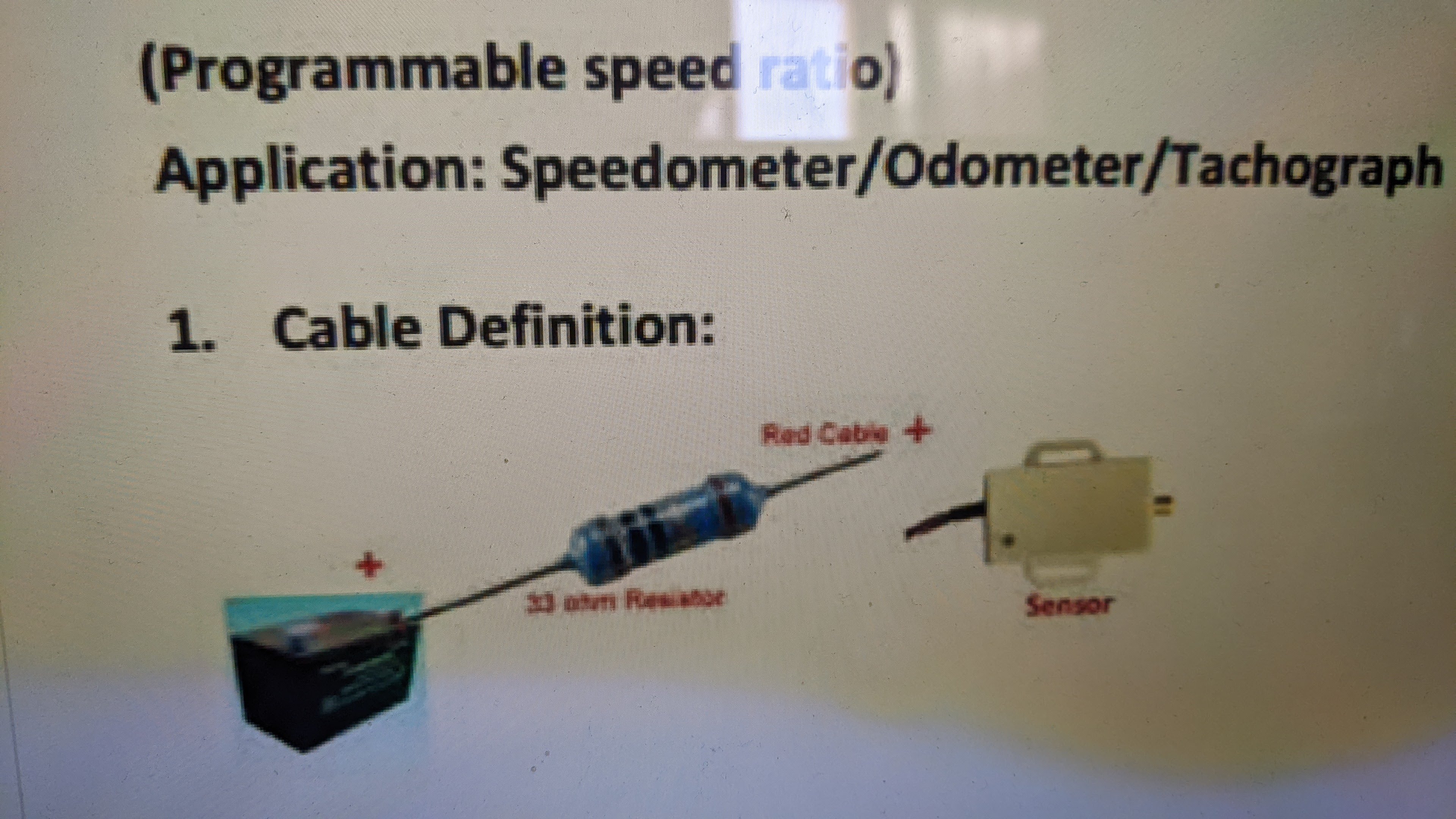
Somewhat confusing diagram.
But let’s give it a go. My interpretation of the supplied information:
The sensing head can be mounted to either the HT cable or the signal cable to the coil. As you don’t have a coil you are restricted to the HT cable, closer to the plug than the mag.
The drawing suggests you have a three pole plug to connect the sensing head to the meter. The meter requires a constant live via the red core by using a “scotch lock”,picking up the supply from the battery.
Now the red/ green and brown leads from the sensing head:
RED: from sensing head is connected to brown cable “scotch locked”
to a switched supply and goes into the meter head.
GREEN: appears to connect to the BLACK lead going to the meter AND THEN GROUNDED.
BROWN: connects to the OTHER core (described as RPM signal) going to the meter head.
Possible issue is that there are TWO brown cores involved…if the sensing head connector is a moulded item it should not be a problem. But if it’s individual items maybe there is the issue.
Summing up, four cores to the meter, one 12v supply, a switched 12v supply, a ground and a pulse signal.
Good luck
Jon
- Log in to post comments
I'll give it a try
Thank you Jon.
I'll give this a check out.
I don't think my positive earth is the issue.
Will report back.
Thanks again,
Neil.
- Log in to post comments
I tried
Hi Jon,
I tried and then other combinations but couldn't get the needle to move.
Also I tried attaching the sensor to just below the other plug.
I may have to ditch the mag and buy a Boyer and coil pack, but not just yet as I know this can be done. Missing a trick, that's all.
Thank you for your help and interest.
Appreciated,
Neil.
- Log in to post comments
Why electronic?
You could just go all retro and fit a Smiths magnetic or chronometric rev counter and keep the mag, like wot I have done. Or be cheapskate and not bother with the tacho. You don't really need one anyway. It doesn't make sense to do away with the magneto for the sake of a cheap electronic tacho.
- Log in to post comments
Mechanical
I Originally wanted to fit a mechanical clock I could get hold of BUT I couldn't find a suitable timing case anywhere.
Same issue with my 650, but with Boyer, coil and power box it was straight fwd.
I know this can be done with a mag.
- Log in to post comments
Suitable timing case
You can modify a standard timing case. As impoverished students, we would build up the boss with araldite and drill the appropriate holes. More sophisticated owners would actually build up the case with weld. Posh or what?
- Log in to post comments
Test the sensor.
Put your switched power supply on to the sensor and check that the voltage appears at the
disconnected Green core; should be the same.
Now if you have a multimeter with a current range. Set the meter up to read current and connect the green core to one lead and the other to ground. You should see a low milliamperes reading. No different to leaving a coil powered, it gets hot.
if you only have a voltage range you can do similar but just keep measuring the voltage while you dab the green core to earth. The voltage should dip slightly as you connect to ground.
The whole set up is the reverse of coil ignition, a primary and a secondary. The switching high voltage to your HT lead is inducing a low level voltage into the sensor coil which then triggers the rev counter head.
Jon
- Log in to post comments
Update
Hi Jon,
My wiring colours are not as per diagram, also included is a photo.
I have a Paul Goff ignition switch and tests were with ignition ON.
Conversion:
Green is Black (Supply) 12.44v
Brown is white (Signal)
Red (Ground) Pos 11.85
Current 4.4 DC. Amps & MA ?
Dabbed = 0 Volts
The bike is Pos Earth.
Hope this helps. And thank you for your interest.
- Log in to post comments
Positive Earth
Does the manufacturer state it is suitable for Positive Earth? Who is the manufacturer Neil? I looked at Smiths Classic but don't see your wiring diagram. When electronics are involved the polarity of supply can be an issue.
The Smiths documentation states for Negative earth only...
Jon
- Log in to post comments
Hi Jon, The issue is that…
Hi Jon,
The issue is that the signal adapter does not mention polarity but the tacho can do either.
See photo.
All my bikes are positive earth so I am always sure to mention that.
Smith's (Puca) put me in touch with this other company to buy the clock as they also sold the signal adapter.
ATB,
Neil.
- Log in to post comments
No big picture...
Neil, the information is in byte size. The bigger picture would help. I attach an interpretation of what you have asked for to date.
Cheers
Jon
- Log in to post comments
To get a GPS sensor that fed…
To get a GPS sensor that fed a digital speedometer to work I had to add a resistor and also feed it with full fat 12v not the 12v within the digital speedo which was current limited.
- Log in to post comments
Wiring mock up
Neil, just note that when you get the installation to function consider protection from over current and ease of disconnection.
Should modification from OEM spec be required (as per JH) feedback to supplier so they can improve the product.
Jon
- Log in to post comments
Sensor?
Thanks Jon and John,
Well the day arrived, all wired up as bite size. It meant taking the back wheel off and the battery out + a re-design of the seat and rear mudguard fitting arrangements. (Took time)
Anyway, all done and started the engine (4 kicks) but sadly no go on the tacho.
Now remember, when I first tried this out without help, I found the sensor got very hot but not the HT lead. The actual sensor appears to have melted a little after that.
This time the sensor did not get hot. I hope because it is now wired up correctly but perhaps the sensor is knackered. I think John raised a good point.
Anyway gents, do I buy a new sensor or can I first test this one.
I know we will solve this one.
Neil.
- Log in to post comments
These sensors normally run…
These sensors normally run at 5V internally, they either have a voltage regulator inside to drop 12v to 5v or the speedo/tacho head has a live 5V feed. If you have a sensor expecting 5v and its fed 12v then it will be fried.
- Log in to post comments
Many thanks Gents: (Jon and…
Many thanks Gents: (Jon and John)
A new sensor will arrive in the morning.
I'll let you know, either way.
Thank you,
Neil.
- Log in to post comments
Long awaited update
Sorry about the wait, gents, a lot going on.
I did get the needle to move a little but not much. But at least I know we are on the right track.
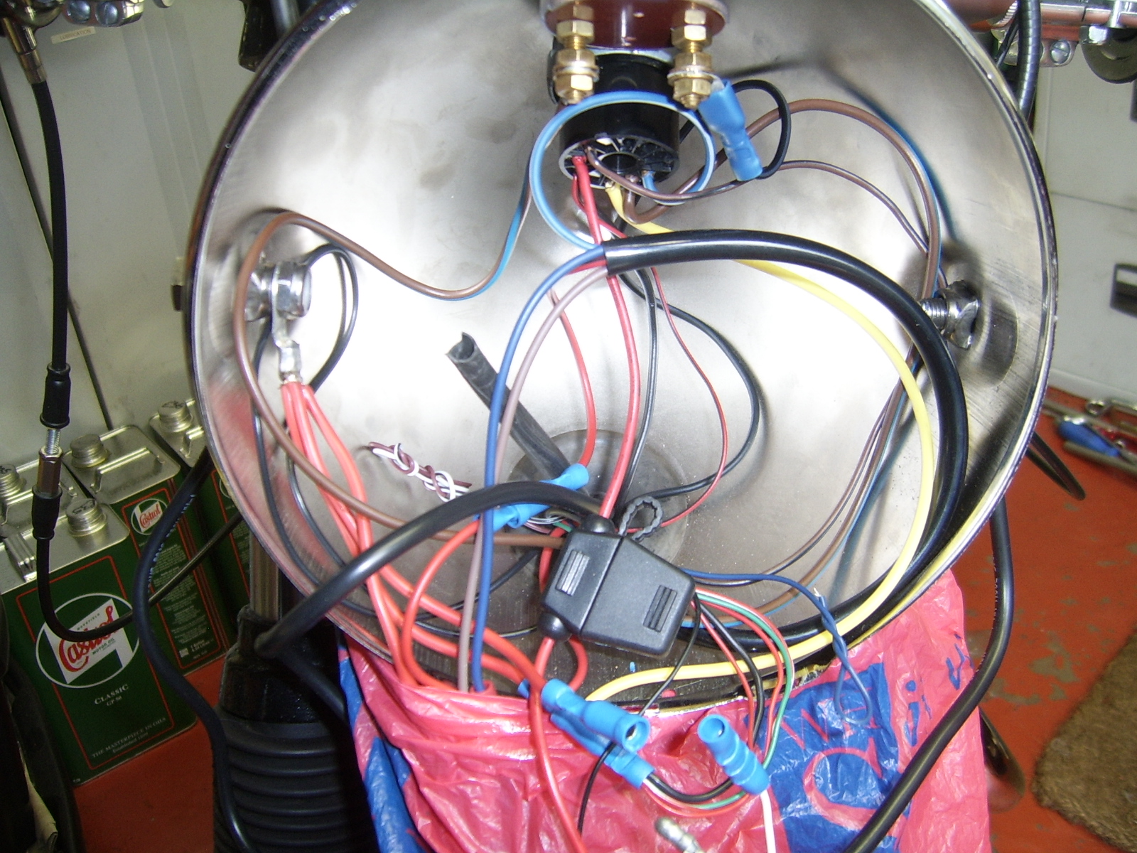
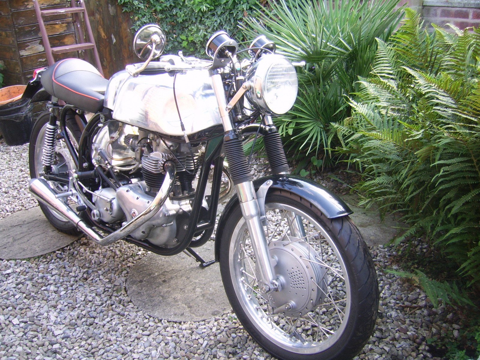
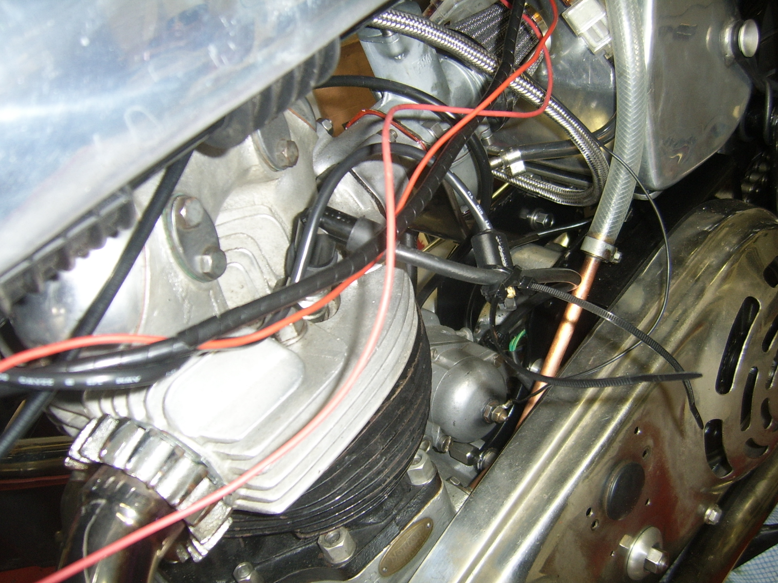
John H's resistor idea is certainly worth thinking about. Pictures below.
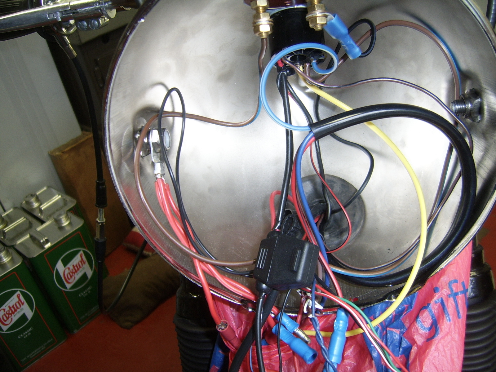
Inside the headlamp (Resistor?)
Wiring under the tank before tidying it up.
Finally the almost finished machine !
Many thanks,
Neil.
- Log in to post comments
Resistor?
Thank you Jon and John.
I looked into resistors but all I could find are those related to flasher units.
I wonder if AO sells something suitable?
Then there is the question of how and where it will be wired.
There was nothing in the instructions about adding a resistor.
Thanks...
- Log in to post comments
33 ohms was the resistor…
33 ohms was the resistor specified for my GPS sensor, which is odd considering its stated input voltage tolerance of 6 to 32V.
- Log in to post comments
sensor
Hello,
wonder if it makes any difference which way round the sensor fits to the ht lead. looking at it in the photo the plug is left of the sensor when it should be to the right side. according to the diagrame. i dont know. just thinking of how a timing light works and has a directional arrow on the sensor.
Barry
- Log in to post comments
Interesting
Thanks Barry, I'll take a look at that.
Just wondering if it's a mirror image?
- Log in to post comments


Instructions are in Chinglise so made in china, says not to cut wires and if there are any questions to contact local distributor.