
This from Mr O - which he must have repeated many times…
“12V reg/rectifiers, these have 2 (mostly YELLOW) input AC wires, these are fed from the alternator which is converted into a two wire by connecting the GREEN/YELLOW to GREEN/BLACK the other alternator wire is the WHITE/GREEN. If you started with the previous 3 colours then your stator would MOST LIKELY is an RM19 which was made for 6V but can easily supply 12V.”
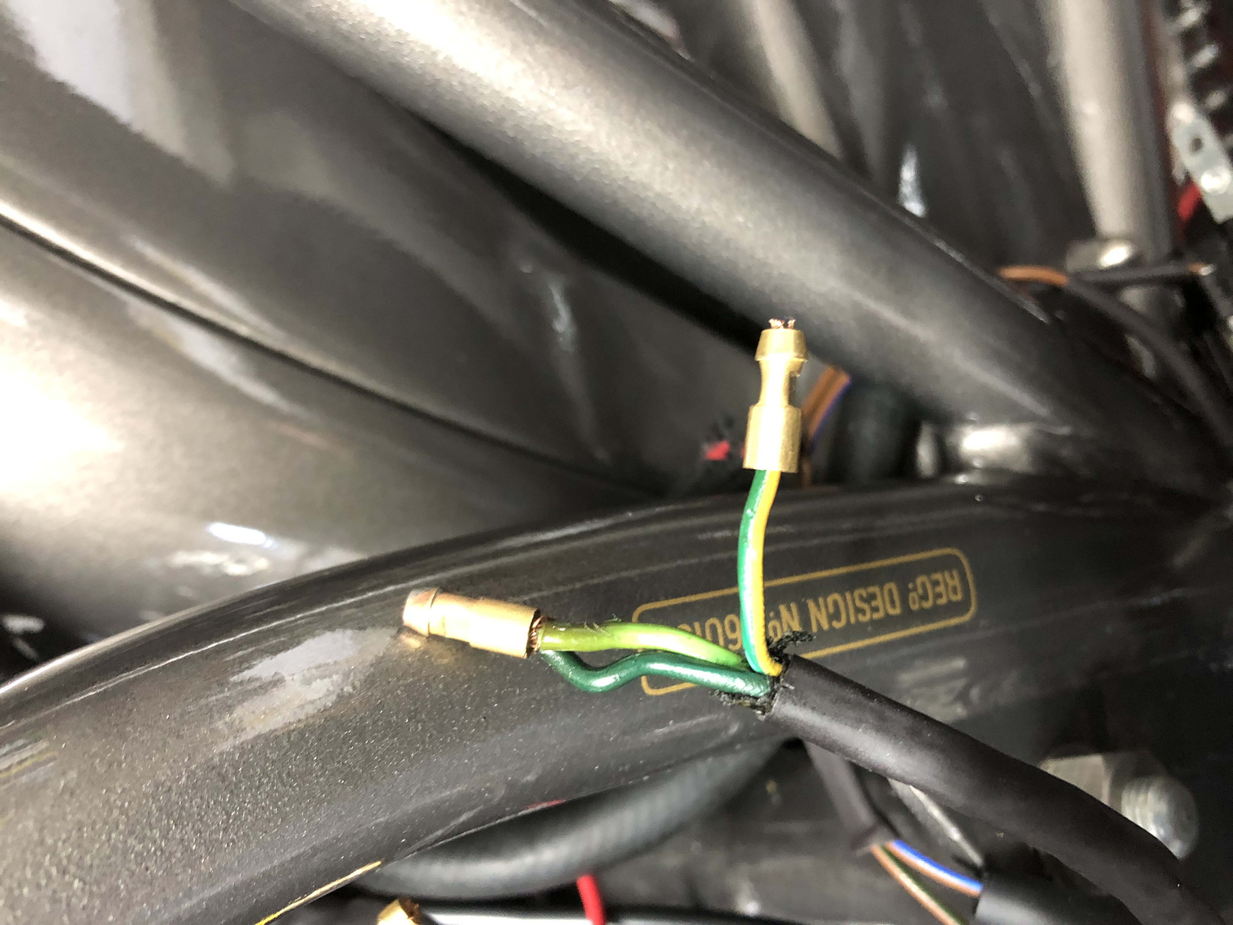
My RM18 wires are indeed different (previous?) colours - see pic attached.
Let’s call them:
GREEN/YELLOW
DARK GREEN
LIGHT GREEN
Which two are joined together to give 2 wire operation and connect to two yellow for reg/rect?
Steve
‘58 Dommie 99 - Boyer/twin coils/AReg1/MC2
In case this is not answered…
- Log in to post comments
That is helpful John - thank…
That is helpful John - thank you.
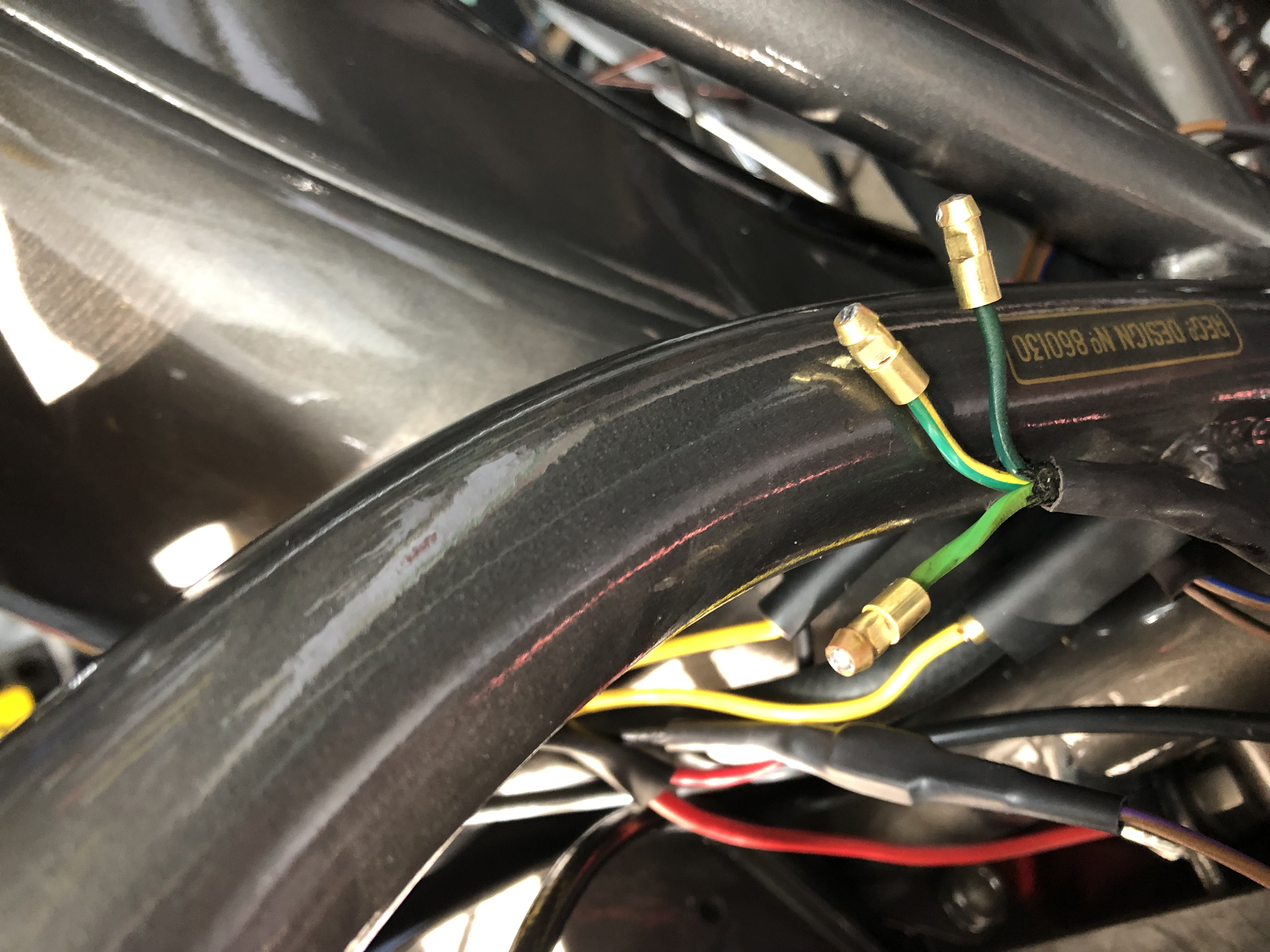
However, I am left with a conflict, assuming my wire colours are Light Green, Dark Green and Green Yellow:
Al says (up to RM19) colour progression over time is:
LG to W to GW
MG to LG to GB
DG to GY
Connect GY and GB (which is LG on my colours) for 12v.
Whereas JRC suggest progression is:
LG to GW
MG to GY
DG to GB
Which for the latter two is the opposite to what Al says.
You will have guessed I’m no electrician… maybe I need one - or an Idiots Guide!
Pic of colours
- Log in to post comments
As you have 2 conflicting…
As you have 2 conflicting sources then you are back to my other 2 suggestions. Comparing diagrams and testing which combination of 2 wires are 2 or 4 coils in circuit.
The JRC info is direct from a Lucas manual but only for RM13/14/15 so you need same for RM18 which should be somewhere in a Lucas PDF on the internet.
- Log in to post comments
Thanks again John. I’ve made…
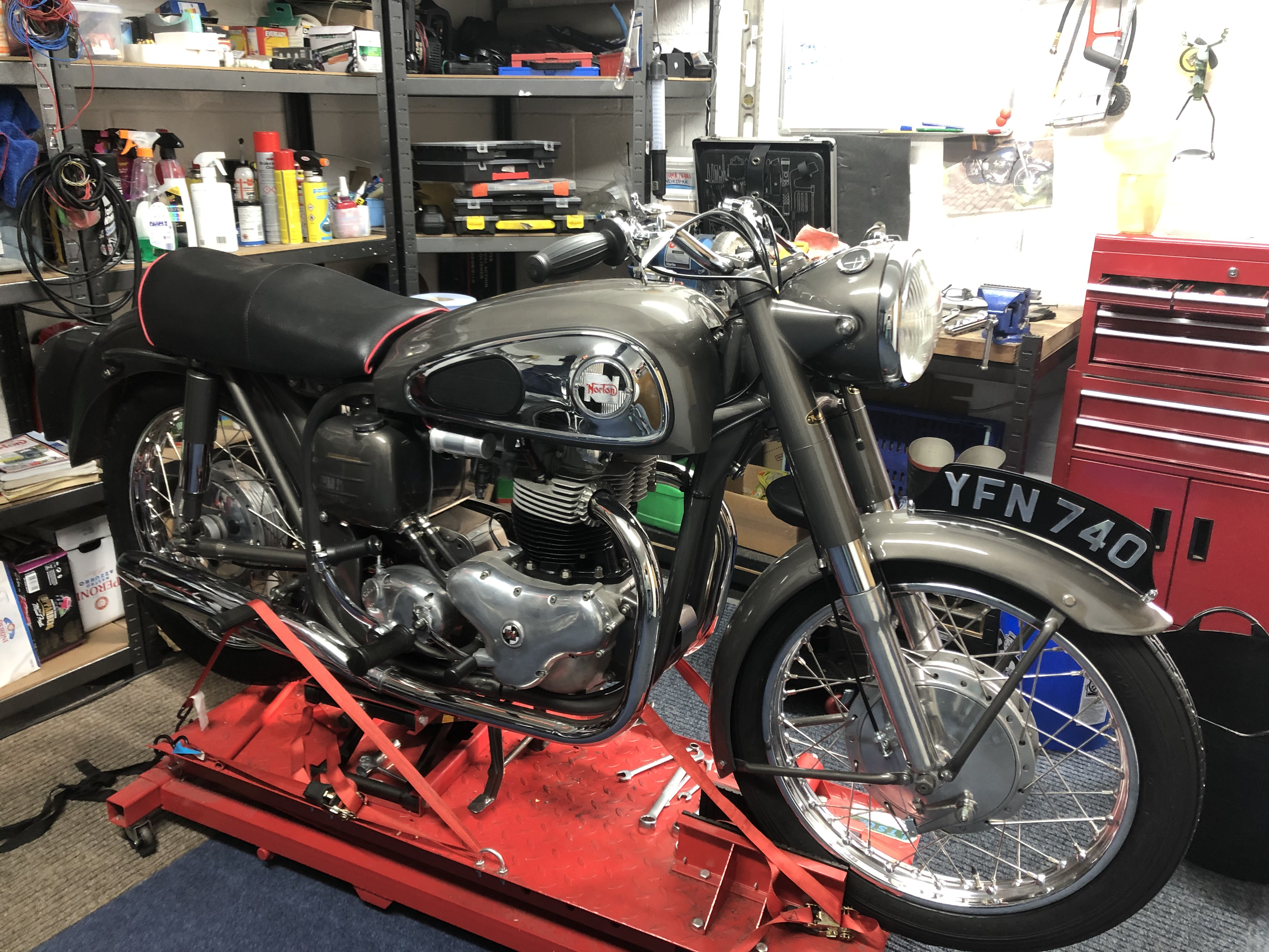
Thanks again John. I’ve made a pragmatic decision and decided that because the only two 1958 original parts on the bike are the RM18 stator/rotor and maybe the clutch plates there is another solution.
It’s taken two and a half years to get to here so let’s not spoil the ship etc etc…
So, I’m replacing both - which means I’ll never know about the wire colours but can be at peace that Nobby (Norton) will be getting his full quota of AC current and maximum drive at the rear tyre!
Thanks again!… pic attached.
Steve
- Log in to post comments
… all the tinwork and the…
… all the tinwork and the engine original - meant the service items!
- Log in to post comments
Looking good. The 'do I add…
Looking good.
The 'do I add the 6V to 12V upgrade' is no longer a simple yes. With the advent of 6V leds which are as bright as the 12V leds (they are all 5V DC internally at the led, a voltage regulator is always inside) but if you have coil ignition then 12V allows the use of EI and keeping the two 6V coils wired in series for the sparks so less outlay.
The current headlamp H4 LED bulb I use is labeled 6 to 24V and works in neg and post earth circuits as it has as part of its voltage regulation circuit a bridge rectifier. It draws 24W and is brighter than the H4 halogen 55/60W bulb it replaced.
- Log in to post comments
A degree of confusion
Indeed such is here. I can see where it comes from (these old colours are on my web site) I will explain later (with a very clear head). But some little points.
LED are not 5V they are ABOUT 2.5V. But to be used in any Automotive situation they need regulation. The power produced at your rear wheel is NOT affected by the power from the alternator. (In fact being pedantic you MIGHT get a smidgen more at the rear wheel if you allowed your alternator to be open circuit).
12V allows the use of EI and keeping the two 6V coils wired in series for the sparks so less outlay.
Again NOT quite so, the Dominator would have had a single 6V coil in the beginning, so buying it 2X6V coils does not save anything. But more on Alternator colour confusion after I have though about it. PS you can't damage the alternator by misconnection, you just get a lower output-nuisance.
- Log in to post comments
Again NOT quite so, the…
Again NOT quite so, the Dominator would have had a single 12V coil in the beginning
? 1958 motorcycle with 12V coil.
- Log in to post comments
Think you got a glitch in…
Think you got a glitch in your copy/paste John… Al said Dominator had single 6 volt coil in the beginning :)
looking forward to the wiring clarification…
steve
- Log in to post comments
Als errors.....
Dominators from the factory were 6V!
Yes there was colour of cable error on my web site, it had been there best part of 20 yrs!! But it is/was not significant as it transposed the High and Low outputs of the very early alternators. When converting to 12V these get connected together any way! And as John says I delved into the world of 1950s alternators as best I could and corrected my web site.
By the way for your delectation, another one of my hobbies is repairing old and not so old radios. I have been trying to repair a 1980s Sony radio, the printed circuit board around the control pad is quite corroded. It is positive earth!!
- Log in to post comments
I am resurecting a Technics …
I am resurecting a Technics Hi fi stack for my grandson who has (out of the blue) developed a passion for old Beatles records after a week in Dublin drinking Guinness and getting off with an Irish girl.
- Log in to post comments


In case this is not answered directly.
Get hold of 2 wiring diagrams, one for 6V RM19 and one for 6V RM18 and compare the alternator wire colours referenced on the diagrams to the connections to the lighting switch and the alternator coils. You should be able to xref from the RM19 to the RM18. Other way is to check the ohms readings between all combinations of 2 wires to identify the 2 coil vs 4 coil connections.
According to this site
https://www.jrcengineering.com/technical-support/lucas-alternator-tips/
Light Green is Green White
Green Yellow is Green Yellow
Dark Green is Green Black
This is half way down the page