
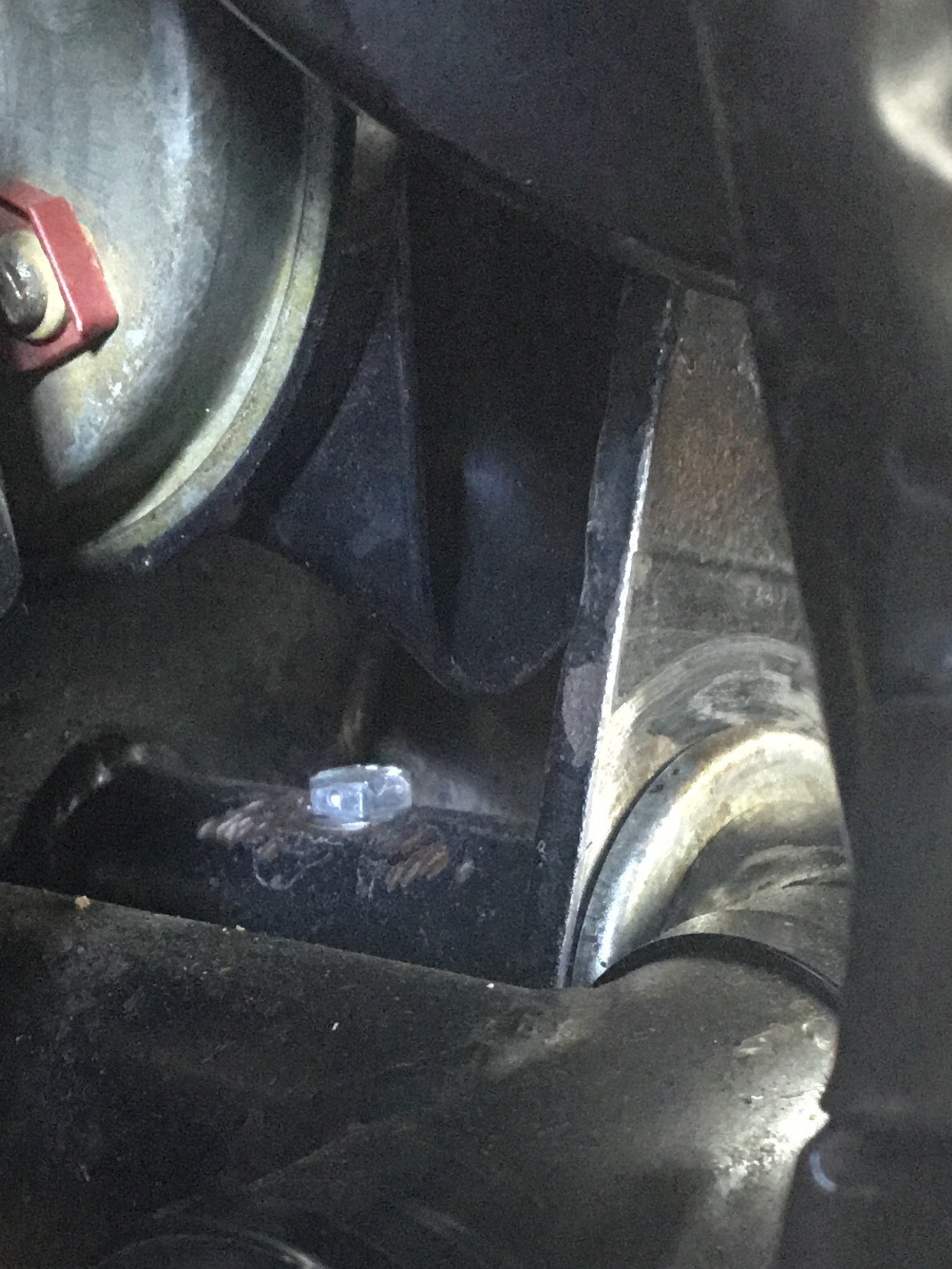
In the midst of a major strip down of the back end of the old Norton and am in the process of removing the swing arm for rebushing. The book tells me that the front engine mount bolt is the correct size/thread to engage and thus remove the pinion. I t doesn't actually tell me what the thread is though? I vaguely recall 1/2" BSF from the dim and distant past. Can anyone confirm this thread size for me as I really dont want to dismantle the front engine mount as well as everything else I have going on at the moment! I would much make a dedicated threaded rod that also suits my slide hammer.
All advice greatly appreciated,
Dave
Previously david_broadbent…
- Log in to post comments
Previously Tony Ripley wro…
Previously Tony Ripley wrote:
Previously david_broadbent wrote:
In the midst of a major strip down of the back end of the old Norton and am in the process of removing the swing arm for rebushing. The book tells me that the front engine mount bolt is the correct size/thread to engage and thus remove the pinion. I t doesn't actually tell me what the thread is though? I vaguely recall 1/2" BSF from the dim and distant past. Can anyone confirm this thread size for me as I really dont want to dismantle the front engine mount as well as everything else I have going on at the moment! I would much make a dedicated threaded rod that also suits my slide hammer.
All advice greatly appreciated,
Dave
Hi Dave,
I may be looking at the wrong bolt but according to the andover norton site it is
BOLT 3/8" UNF x 4 1/8"
part-no: 06.3213
But if you look athttps://andover-norton.co.uk/en/shop-drawing/204/engine-mountings-head-steady-centre-stand
You should be able to confirm.
Regards
Tony
Tony,
thanks for the prompt response and the reference drawing. I think from that drawing, the bolt I am interested in is item 14, which is simply called Bolt - part number 06.0423. No thread size given. More helpfully though, the nut, item 16, quotes 1/2" UNF. Result!
Thanks again,
Dave
- Log in to post comments
And don't forget to lubri…
And don't forget to lubricate your swinging arm via the nipple with EP 140.
- Log in to post comments
David: One reference lists…
David:
One reference lists part no. 06-0423 as the following:
Bolt, 1/2CEIX20X7" Engine Mounting Front
Hope that this helps
Mike
- Log in to post comments
CEI is Cycle. I would have…
CEI is Cycle. I would have expected the Commando to be UNF as mentioned by David as this part is unique to Commandos.
AFAIK the only Cycle threads on Commandos were those inherited from earlier models, eg the gearbox cover studs.
- Log in to post comments
Thank you all for your adv…
Thank you all for your advice - muc h appreciated. I was able to make a suitably threaded piece to attach to my slide hammer and now have the spindle in my hands.
I thought you might bew interested in the state of the spindle and particularly the bushes.
My decision to strip it all out was a marginal one as although there was play, I didn't think it excessive over the length of the swingarm - but look at the photos of the bushes! I have no idea how such deep scoring could have come about - unless it's as a result of the corrosion in the spindle? I know the bike had been stood for quite a few years following an accident prior to my buying it, which probably accounts for the corrosion?
Finally, somebody in the Roadholder mag years ago wrote about a mod to introduce a small tube into the swing arm - soldered in adjacent to the locking blot - to which a plastic pipe could be attached, run up under the seat and ever after topped up with the correct oil. The advantage of course is simplicity and also a sight glass of oil "content" in the bearings. Having got the thing apart with the intent of embodying this mod, I'm not sure how this oil would actually get to where it needs to be?
Any comments?
Attachments
img_2436-jpg
- Log in to post comments
I vaguely remember this. A…
I vaguely remember this. An easier mod would be to replace the grease nipple with something like a brake bleed nipple drilled through and your plastic tube attached to the end of that. Easier to see (but also easier to kick off).
As long as you don't put grease in the nipple! I have one of those little hand-held grease guns that I used to keep filled with SAE140 just for the Commando swinging arm.
- Log in to post comments
Yes, I had thought about t…
Yes, I had thought about that - brake bleed nipple through the endplate. It's pretty much set back from wandering boot theels so should be ok from that respect. It would mean that the "chamber " was never more than half full though - whereas the same bleed nipple, tapped in from above, would be much better able to keep the chamber full of the SAE140?
I attach another snap of rusted spindle.
Attachments
img_2438-jpg
- Log in to post comments
Seems pretty well worn out…
Seems pretty well worn out to me....
If your plastic tube extended above the spindle level as you suggest then the head in it would keep the level within the spindle fairly high. In any case, the felt should help.
- Log in to post comments
Previously ian_soady wrote…
Previously ian_soady wrote:
Seems pretty well worn out to me....
If your plastic tube extended above the spindle level as you suggest then the head in it would keep the level within the spindle fairly high. In any case, the felt should help.
I have been trying, so far unsuccessfully, to achieve a tight dry iteration of the original elegant design and so avoid the complication of clamps etc tried elsewhere. see NYC Norton aftermarket offering for example.
Mechanisms to witness oil levels are redundant while oil leaks out. While there is oil to leak there will be oil to lubricate.
The quest to date...
Removed the Inner Primary and reamed the spindle tube for oversized spindle. ( With the Inner Primary off the Rear Engine Mount is more accessible for maintenance / upgrade.)
Polished cradle bearing faces / seal surface. Relieved cradle edges to avoid seals catching and getting cut on installation. ( Watch closely as the swing arm goes back in for pinching of the seals)
Rear Isolastic shims outside dust cover to eliminate any side clearance before fitting seals prior to final installation. Silicone to any potential location for oil leaks. If you are fettling this with the Inner Primary on then the LH End Cap needs to be fitted before the Swing Arm goes back in.
Trim a cone shape to a 1/4 UNF bolt to pickup the correct position for the spindle with a lock nut on your long 1/2 UNF spindle extractor / insertion bolt so you can rotate the spindle into position.
I marked the 1/4 UNF retaining bolt to be able to monitor that it doesn't start to vibrate off.
I laid the bike over, removed the nipple and put oil in with a syringe and tube to avoid pressurising the reservoir with the risk of blowing out the seals. Probably best to leave some space for air to expand and compress with changes of temperature.
This all stayed nice and dry for about 48 hours till I took the bike out for a ride..." A norton without oil leaks is a Norton without oil?" Don't you love them?
Next I will try tighter shimming and quad ring seals.
Attachments
IMG_0040.JPG
- Log in to post comments
Previously robert_percival…
Previously robert_percival wrote:
Previously ian_soady wrote:
Seems pretty well worn out to me....
If your plastic tube extended above the spindle level as you suggest then the head in it would keep the level within the spindle fairly high. In any case, the felt should help.
I have been trying, so far unsuccessfully, to achieve a tight dry iteration of the original elegant design and so avoid the complication of clamps etc tried elsewhere. see NYC Norton aftermarket offering for example.
Mechanisms to witness oil levels are redundant while oil leaks out. While there is oil to leak there will be oil to lubricate.
The quest to date...
Removed the Inner Primary and reamed the spindle tube for oversized spindle. ( With the Inner Primary off the Rear Engine Mount is more accessible for maintenance / upgrade.)
Polished cradle bearing faces / seal surface. Relieved cradle edges to avoid seals catching and getting cut on installation. ( Watch closely as the swing arm goes back in for pinching of the seals)
Rear Isolastic shims outside dust cover to eliminate any side clearance before fitting seals prior to final installation. Silicone to any potential location for oil leaks. If you are fettling this with the Inner Primary on then the LH End Cap needs to be fitted before the Swing Arm goes back in.
Trim a cone shape to a 1/4 UNF bolt to pickup the correct position for the spindle with a lock nut on your long 1/2 UNF spindle extractor / insertion bolt so you can rotate the spindle into position.
I marked the 1/4 UNF retaining bolt to be able to monitor that it doesn't start to vibrate off.
I laid the bike over, removed the nipple and put oil in with a syringe and tube to avoid pressurising the reservoir with the risk of blowing out the seals. Probably best to leave some space for air to expand and compress with changes of temperature.
This all stayed nice and dry for about 48 hours till I took the bike out for a ride..." A norton without oil leaks is a Norton without oil?" Don't you love them?
Next I will try tighter shimming and quad ring seals.
Robert, I can see you have put some real thought and effort into this - and certainly deserved a better result!
In my humble opinion I think the problem with the design is that as soon as the bike is ridden, the side loads from the swingarm will compress the O rings on one side of the arm, which relieves pressure at the other side and hey presto - a small leak. This is why your bike was leak free until you rode it. Multiply that by every bump and corner and the oil chamber will ultimately drain. To eliminate this would require a major redesign that doesn't leave it to an O ring to maintian the basic geometry of the suspension as well as preventing oil leaks! Alternatively - modify the bushes and swing arm to take grease nipples and just grease the thing! Think of all of those rear swing arm bushes on Mini's. I can't see there much of a difference in application - although access might be an issue - which is maybe why they went to oil in the first place??
To have done all you have and still not cracked the problem is disappointing - but no worse than your rear chain I suppose - It's just something you oil periodically. What you will have achieved is minimising the rate at which the oil leaks!
I think your point about not pressurising the oil chamber is a very valid one though - which is actually why I first considered the plastic tube sight glass/filler idea.
Finally, regarding the comment Ian made about felt washers - I think that only applies to later Commandos - there were certainly none on my Mk2A when I dismantled it?
- Log in to post comments
IIRC (which I probably don…
IIRC (which I probably don't) the felt was a cylinder in the middle of the spindle as well as a disc on the end. I definitely had them on my 1974 828 Mk 1.
- Log in to post comments
Previously ian_soady wrote…
Previously ian_soady wrote:
CEI is Cycle. I would have expected the Commando to be UNF as mentioned by David as this part is unique to Commandos.
AFAIK the only Cycle threads on Commandos were those inherited from earlier models, eg the gearbox cover studs.
Phil Hannam has sent me the information below:-
This comment could be a little misleading as the Commando engines had CEI threads & nuts in quite a few places up to 1972.
eg.......Cylinder Head bolts and Barrel Base studs
Post 1971 the Barrel base studs changed to UNF threads & nuts but the cylinder heads kept faithful to CEI Headbolts & studs.
Inside the timing cover........the oil pump gained a UNF size nut on the drive shaft but I believe the hthread remained as CEI. The camchain and oil pump body nuts remained as CEI jobs. Likewise the studs on the oil pump were CEI at both ends. As were the two front cylinder barrel studs.
There may be others worth a small mention such as rocker cover studs and nuts.
- Log in to post comments
Previously Tony Ripley wro…
Previously Tony Ripley wrote:
Previously ian_soady wrote:
CEI is Cycle. I would have expected the Commando to be UNF as mentioned by David as this part is unique to Commandos.
AFAIK the only Cycle threads on Commandos were those inherited from earlier models, eg the gearbox cover studs.
Phil Hannam has sent me the information below:-
This comment could be a little misleading as the Commando engines had CEI threads & nuts in quite a few places up to 1972.
eg.......Cylinder Head bolts and Barrel Base studs
Post 1971 the Barrel base studs changed to UNF threads & nuts but the cylinder heads kept faithful to CEI Headbolts & studs.
Inside the timing cover........the oil pump gained a UNF size nut on the drive shaft but I believe the hthread remained as CEI. The camchain and oil pump body nuts remained as CEI jobs. Likewise the studs on the oil pump were CEI at both ends. As were the two front cylinder barrel studs.
There may be others worth a small mention such as rocker cover studs and nuts.
That's why I made the statement about components being inherited from earlier models, which include the ones you mention. I didn't intend to mislead anyone, just to state that any parts specifically for the Commando would have been UNF / UNC.
- Log in to post comments
Your quad ring plan is goo…
Your quad ring plan is good. the bushes need to be tight enough on the gearbox cradle to stay put where ever you let them sit. I drilled out the middle of the grease nipple and fitted a silicon rubber tube up the the rear of the oil tank. The fastback didn't have a dipstick. but I made one and it lives in the tube. So every time you check the oil level and stow the dipstick, what is left on the dipstick drains down through the tube into the swinging arm bearing. you can squirt a bit more down there with an oil can if you fancy. I also fitted a bigger diameter rod through the middle of the shaft and made some better end caps to do away with the crappy little spoke size rod. (whoever designed that engineering miracle should have been shot at dawn)
- Log in to post comments
The stronger rod has got t…
The stronger rod has got to be an improvement. Chase a leak in the outer seals by stretching the original too far and you have a big job to do without delay. The larger inner seals are probably the more vulnerable to leaking and not affected by the sealing of the end caps.
Hallelujah Hallelujah!
My Swing Arm bearings have stopped leaking without the chore of tighter shimming and quad rings.
I'm pretty sure this is not because all the oil has leaked out.
2 things changed...
I took some trouble to get the rear wheel into better alignment and...
I took the bike our for a 4 hour, at times brisk, ride in our southern summer sun. This would have given the new seals a chance to bed in.
When you think about it rear wheel alignment is an important factor in the correct functioning of the Swing Arm bearings.
Now to fix the weep under the oil tank and the leaks at the cylinder / crankcase faces.
For those in the North, take heart, the days are getting longer.
Robert.
- Log in to post comments
After I had replaced the i…
After I had replaced the inner o rings I noticed that there was a little loop of o ring sticking out from under its cup. Bugger. (it's still there) When they are not leaking they are empty. With the swinging arm only moving about 10 degrees, if that, the rotation of the bush is going to be about 2mm max. probably bed in in about 250,000 miles
- Log in to post comments
Previously robert_percival…
Previously robert_percival wrote:
Previously ian_soady wrote:
Seems pretty well worn out to me....
If your plastic tube extended above the spindle level as you suggest then the head in it would keep the level within the spindle fairly high. In any case, the felt should help.
I have been trying, so far unsuccessfully, to achieve a tight dry iteration of the original elegant design and so avoid the complication of clamps etc tried elsewhere. see NYC Norton aftermarket offering for example.
Mechanisms to witness oil levels are redundant while oil leaks out. While there is oil to leak there will be oil to lubricate.
The quest to date...
Removed the Inner Primary and reamed the spindle tube for oversized spindle. ( With the Inner Primary off the Rear Engine Mount is more accessible for maintenance / upgrade.)
Polished cradle bearing faces / seal surface. Relieved cradle edges to avoid seals catching and getting cut on installation. ( Watch closely as the swing arm goes back in for pinching of the seals)
Rear Isolastic shims outside dust cover to eliminate any side clearance before fitting seals prior to final installation. Silicone to any potential location for oil leaks. If you are fettling this with the Inner Primary on then the LH End Cap needs to be fitted before the Swing Arm goes back in.
Trim a cone shape to a 1/4 UNF bolt to pickup the correct position for the spindle with a lock nut on your long 1/2 UNF spindle extractor / insertion bolt so you can rotate the spindle into position.
I marked the 1/4 UNF retaining bolt to be able to monitor that it doesn't start to vibrate off.
I laid the bike over, removed the nipple and put oil in with a syringe and tube to avoid pressurising the reservoir with the risk of blowing out the seals. Probably best to leave some space for air to expand and compress with changes of temperature.
This all stayed nice and dry for about 48 hours till I took the bike out for a ride..." A norton without oil leaks is a Norton without oil?" Don't you love them?
Next I will try tighter shimming and quad ring seals.
Robert,
what do you mean by quad ring seals? Sounds like a simple inprovement whilst I have the thing in bits. I also think the shimming is a great idea.
Dave
- Log in to post comments
Hi Dave, the below screen…
Hi Dave,
the below screen shot describes quad rings.
there are extensive debates on the Access Norton website...some seem to be able to achieve an oil tight seal, some accept a slow leak and arrange total loss replenishment, comnoz recommends an even thicker oil, some give up in disgust and resort to periodic greasing. There had been some synthetic bushes available not requiring lubrication in the states. Rusting of the spindle seems to have been the principal cause of wear and can require resort to desperate measures to remove an affected spindle.
Look forward to an update on your progress, I'm living with a slow leak till I get quad rings into town ( 223 large; 212 small ...3rd hand info worth checking against 060449 & 060448 before you found yourself high and dry with the wrong spec rings ) and make the time to put them in. So far it's not actually dripping...give it time.
Robert.
Attachments
img_0098-png
- Log in to post comments
Thank you for that. I had…
Thank you for that. I had never heard of quad rings but I'm all over them now!
I have just been talking to one of the main UK suppliers - Eastern Seals. Very helpful young lady. They needed the inner diam and the cross section. I've taken the o/d of the bush flange at 41.26 as the guide here. They can do a 41.28 or a 42.8. I have gone with the latter. They also do that diameter with a cross section of 3.53, which compares well with 3.46 diam, which was what I got from measuring the standard o ring.
The result is quad ring BS826.
Unfortunately they have none on the shelf so they need to get a quote from their supplier. I await the quote with some interest and let you know what they offer.
Dave
- Log in to post comments
Just heard back from Easte…
Just heard back from Eastern Seals. A pair of BS826 quad seals is - wait for it £29 plus VAT! The thick end of £18 each. However, for an order of 10 off, the price drops to £7.50 each. No idea what 100 off would cost!
Is there enough interest out there in the club membership to warrant putting my hand up for ten off?
- Log in to post comments
This is where I get my O a…
This is where I get my O and X rings from
The per ring price is low but there is shipping cost from US, but it works out cheap if you have a number of different rings to buy so get measuring all the rings on the bike including the ones you did not know you needed, like the X ring for the kickstart shaft, the one you are looking for on the swing arm is 53 cents each. Sadly the UK is behind on this type of website.
- Log in to post comments
Hi John and Dave, There ar…
Hi John and Dave,
There are a number of classification systems for quad rings ( x rings).
See below from the Access Norton web site with some Commando seals listed if one wanted to get sets to spread the cost of shipping.
Regards,
Robert.
Attachments
img_0096-png
- Log in to post comments
Previously Dave Broadbent…
Previously Dave Broadbent wrote:
In the midst of a major strip down of the back end of the old Norton and am in the process of removing the swing arm for rebushing. The book tells me that the front engine mount bolt is the correct size/thread to engage and thus remove the pinion. I t doesn't actually tell me what the thread is though? I vaguely recall 1/2" BSF from the dim and distant past. Can anyone confirm this thread size for me as I really dont want to dismantle the front engine mount as well as everything else I have going on at the moment! I would much make a dedicated threaded rod that also suits my slide hammer.
All advice greatly appreciated,
Dave
I made a permanent oiler for the swingarm on my 71 Commando,by cutting the head off a 2" x 1/4 unf bolt,drilling it carefully 1/8" right through in a lathe and using a locknut ,screw it into the swingarm pin a few turns,then nip up the locknut. A small diameter clear plastic tube can then be pushed over the plain shank and secured in place with a small clip.The tube is run up under the seat ,cable tied in place and is then filled with SAE 140 oil- Slowly!!. The bushes will then never run dry,and the tube rarely need stopping up.I must get some of the quad ring seals, 'cos the only oil leak on the bike is the occasional drip from the swingarm!! You can't have everything!
- Log in to post comments
Previously ronald_proctor…
Previously ronald_proctor wrote:
Previously Dave Broadbent wrote:
In the midst of a major strip down of the back end of the old Norton and am in the process of removing the swing arm for rebushing. The book tells me that the front engine mount bolt is the correct size/thread to engage and thus remove the pinion. I t doesn't actually tell me what the thread is though? I vaguely recall 1/2" BSF from the dim and distant past. Can anyone confirm this thread size for me as I really dont want to dismantle the front engine mount as well as everything else I have going on at the moment! I would much make a dedicated threaded rod that also suits my slide hammer.
All advice greatly appreciated,
Dave
I made a permanent oiler for the swingarm on my 71 Commando,by cutting the head off a 2" x 1/4 unf bolt,drilling it carefully 1/8" right through in a lathe and using a locknut ,screw it into the swingarm pin a few turns,then nip up the locknut. A small diameter clear plastic tube can then be pushed over the plain shank and secured in place with a small clip.The tube is run up under the seat ,cable tied in place and is then filled with SAE 140 oil- Slowly!!. The bushes will then never run dry,and the tube rarely need stopping up.I must get some of the quad ring seals, 'cos the only oil leak on the bike is the occasional drip from the swingarm!! You can't have everything!
Ronald,
I'm just at that point now and intend to follow a similar line - but how the hell do you drill/tap the swing arm spindle - or did you just utilise the original single anchor bolt?
- Log in to post comments


Previously david_broadbent wrote:
Hi Dave,
I may be looking at the wrong bolt but according to the andover norton site it is
BOLT 3/8" UNF x 4 1/8"
part-no: 06.3213
But if you look athttps://andover-norton.co.uk/en/shop-drawing/204/engine-mountings-head-steady-centre-stand
You should be able to confirm.
Regards
Tony