
My '74 mk2a Commando will pop but not start. It is fitted with a Boyerbransen ignition. Boyerbransen told me to reverse the 2 wires from the static part. I did and it still won't start.
Specifically I want to know how to remove the rotating part.
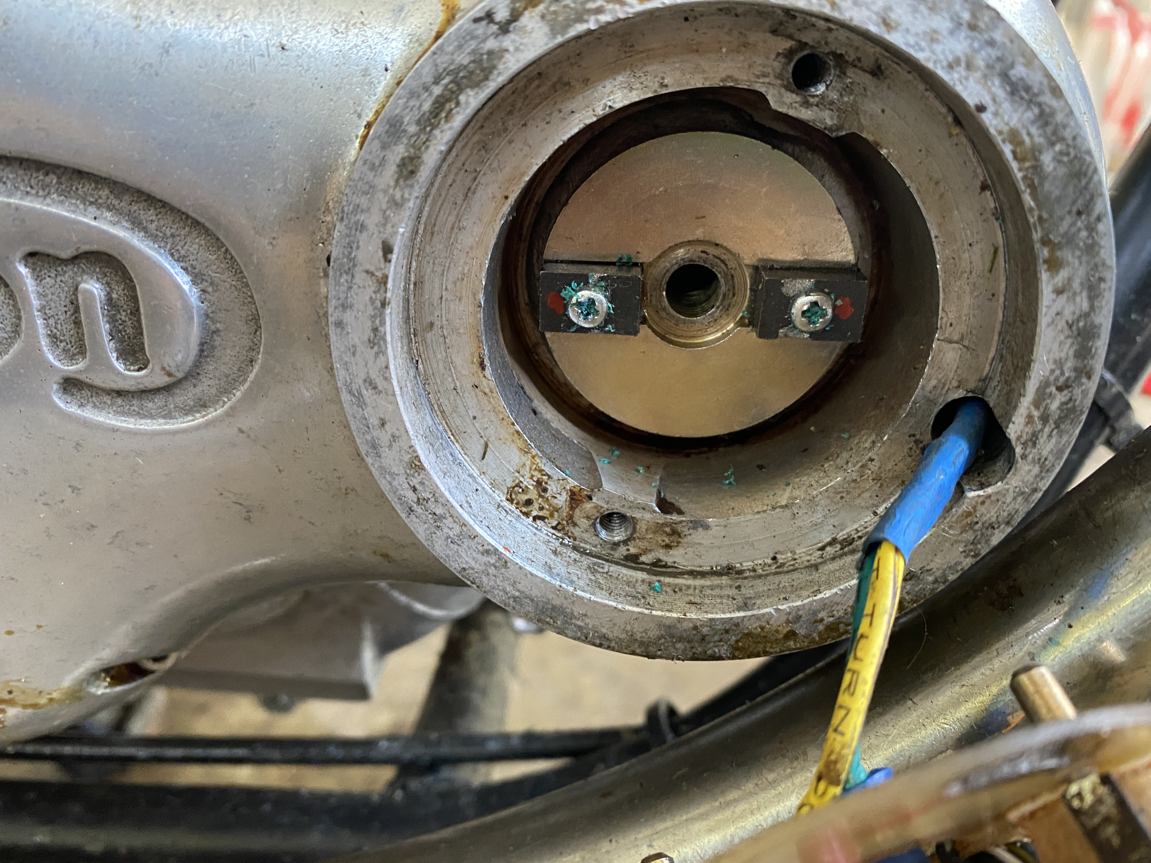
See photo below which shows the rotating part. It's stuck and won't budge.
Here you go...
- Log in to post comments
Thank You Grant
I have the allen head cap screw and will hopefully succeed as per your suggestion.
- Log in to post comments
Hit The Cap Screw with a 3lb Mechanics Hammer
Grant,
Took yours and others suggestion and Hit The Cap Screw with a 3lb Mechanics Hammer.
Didn't budge, even tried a channel locking pliers gently pulling on the plastic magnet holders and it still didn't yeild.
- Log in to post comments
Rotor Is Out
Grant,
As soon as the threaded in the 5/16' bolt it popped out.
Ron Wellman
- Log in to post comments
Thank You Grant
Took yours and others suggestion and Hit The Cap Screw with a 3lb Mechanics Hammer.
Didn't budge, even tried a channel locking pliers gently pulling on the plastic magnet holders and it still didn't yeild.
- Log in to post comments
OR
Just give it a sharp tap with a small hammer-it will fall off. Breaks the taper.
Take NOTE-Reversing the pickup wires will cause the ignition to be fully retarded ie no advance. IF it was reversed to begin with, ie this was the 'poping' only when trying to start and would not start , the reversing of the two wires gets the advance back, bingo engine starts.
If the pickup wires were CORRECT (with advance) then reversing them gives you fully retarded ignition and the machine will NOT want to start, if it did it would sound very 'flat'.
Take note going back to points is a backward step in the long run.
Please get in touch directly if you still are having a problem.
Al Osborn. aoservices.co.uk
- Log in to post comments
Thank You Alan
Took yours and others suggestion and Hit The Cap Screw with a 3lb Mechanics Hammer.
Didn't budge, even tried a channel locking pliers gently pulling on the plastic magnet holders and it still didn't yeild.
Other suggestions please?
- Log in to post comments
Plastic?
The rotor is a steel plate with 2 very strong rare earth magnets screwed/glued in slots. Early rotors only had the magnets screwed on-they flew off! So dropping them in slots and with a touch of epoxy glue assures us they stay!
By the way if anyone ever thinks of remaking this part for another motorcycle, or even rebuilding into a magneto body, then be careful the magnets normally have South Poles to the outside. If you inadvertently reverse one-it will NOT work. If you inadvertently reverse them both then you loose the advance curve! (See other posts) but of course you would then have to reverse the Pick Up wires to regain the advance curve.
- Log in to post comments
Tried to Post In The "open forum" But Could Not
Ian,
See photo below.
I clicked on the miscellaneous icon and expected to allow to post my issue about removing the Boyerbransen rotor.
Ron Wellman
Midland, MI USA
- Log in to post comments
Not quite so Ian
Answering such problems are a lot easier by phone or personal emails, if a statement is not fully understood between the parties it is no matter we get sorted, if it is on here then people some times get the wrong angle. When I write on here I am well aware that the 'whole world' is watching and I place my words (sometimes!) carefully. Don't worry Ian my dealing with electronic ignition will not affect your magnetos as you say. The advance retard on your magneto might be manual ie long cable to the handle bar or a flying bob weight system in the timing cover. The majority of magnetic Pick Up triggers have the ignition advance built into the magnets or soft iron flying past the pickup coil. IF the coil connections are reversed the advance gets cancelled and you end up with a fully retarded condition. RITA ignitions 'can' start if reversed but the advance is lost and the response of the engine is 'rubbish'.
- Log in to post comments
Hi Gary, If you mean…
Hi Gary,
If you mean swapping the wires end to end (which I am sure you don't) then you are correct.
However, if you consider that as the magnets go flying past the pickup, you get a positive going pulse and the unit triggers on the rising edge.
If you swap the wires around you will get a negative going pulse As the system will still trigger on the rising edge, , this is now as the magnet is moving away.
As the advance function only works on the leading edge (which is now going negative and not producing the spark), you will have no advance.
Hope this makes sense.
Tony
- Log in to post comments
Rotor Is Out
Gary,
As soon as I threaded in the 5/16" bolt the rotor popped out.
Ron Wellman
- Log in to post comments
On earlier boyer stuff you…
On earlier boyer stuff you had to give the bolt a slightly sideways tap to release.
- Log in to post comments
You are using a 5/16" cap…
You are using a 5/16" cap screw and not a 1/4" cap screw ?
Only the 5/16" cap screw is for extraction, the 1/4" screw will hold it in and you risk damage to the cam shaft if you hit it too hard.
- Log in to post comments
I was using the 1/4' Cap Screw
John,
Duh !, I was using the 1/4' Cap Screw.
I assume the 5/16" cap screw is fine thread like the 1/4' Cap Screw.
Thank you for pointing out my error.
Ron Wellman
- Log in to post comments
Rotor Is Our
John,
As soon as I screwed in the 5/16" bolt it popped out.
Perhaps because I had loosed it by hammering of the 1/4" bolt.
Ron Wellman
- Log in to post comments
Thank You Alan
My magnets are attached with small machine screws and fortunately I have had no problems with them flying off.
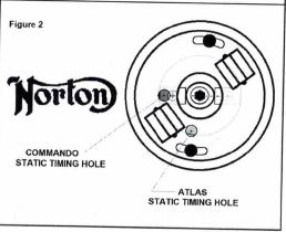
My quandary now that the rotor is off is to identify the "Commando Timing Hole" as per the attached
photo of the Boyer Bransden installation instructions. Please also open CamShaftEnd and pay close attention to the text. The text asks the question "is this the Commando Static Timing Hole" near the number 1
- Log in to post comments
The 2 holes in the timing…
The 2 holes in the timing cover are used mount the stator and show as the 2 black holes with the slotted holes in the stator, the stator has a further 2 holes either side of the pickup coil that you use to get the magnets in the correct position. As there is one hole for anti clockwise and one for clockwise rotation you use the Commando one when the engine has the rotor fitted on the end of the camshaft. I fit the rotor loosely, get the engine to 31 degrees before TDC, fit the stator and move then move the rotor so a magnet is under the Commando hole and then tighten the rotor with the 1/4" allen bolt. That gives you the initial timing that you must confirm by strobe as it is normally too advanced.
- Log in to post comments
Thank You John
Thank You John,
How do I determine "31 degrees before TDC" and how do I determine where the Commando hole is ?
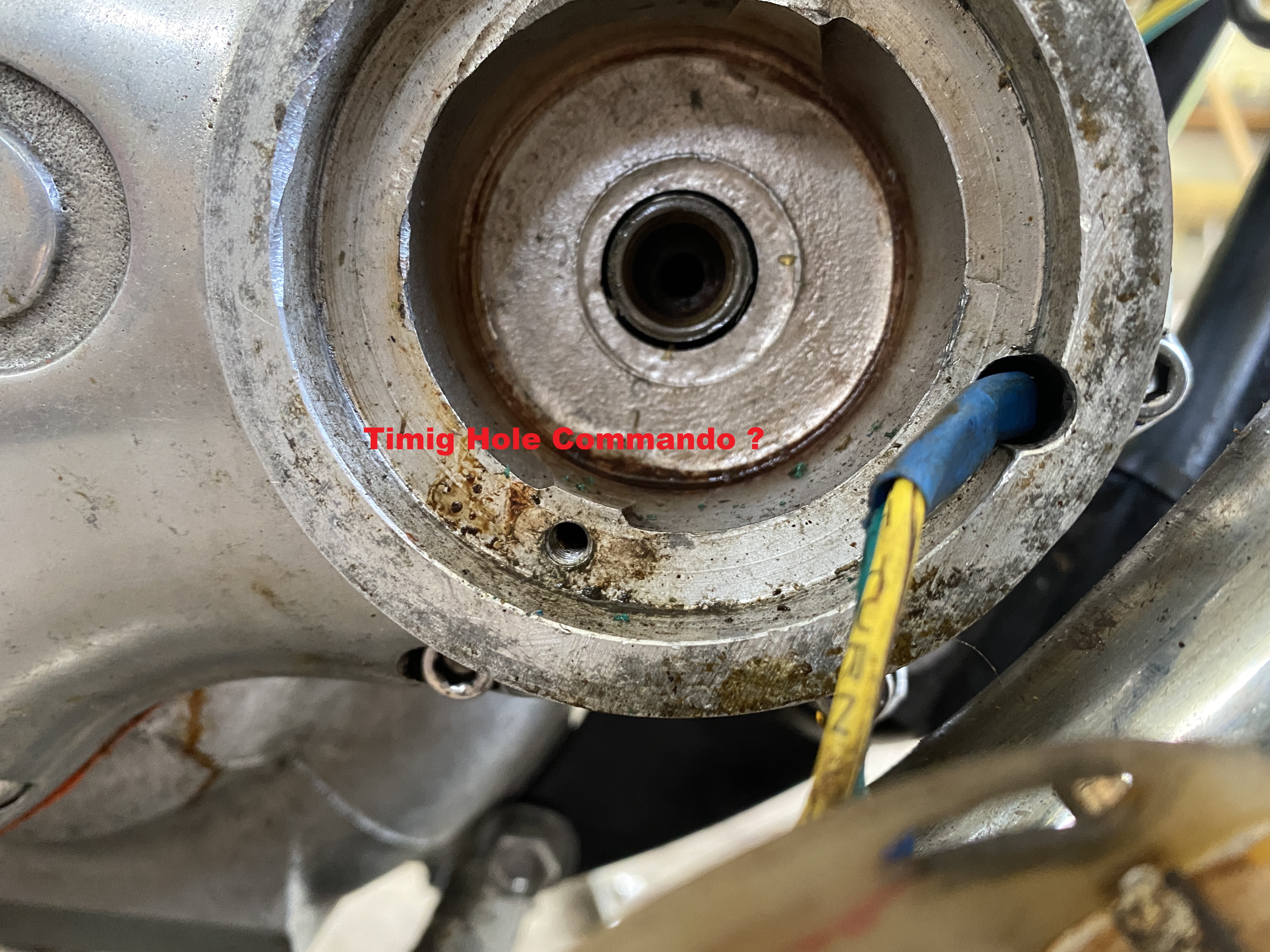
See attached photo. Is the "Commando Hole" the barely discernible circular spot on the rotor ?
- Log in to post comments
The Commando hole is on the…
The Commando hole is on the Boyer Stator plate and is not part of or on the timing cover.
Look at page 4, fig 1 is of the timing cover with just the rotor installed in the timing cover, note no commando hole, page 4 fig 2 shows the boyer stator plate installed and the commando hole identified on the boyer stator plate.
http://www.boyerbransden.com/pdf/KIT00053.pdf
The timing procedure is detailed in the riders handbook, see page 26
http://britmoto.com/manuals/Manuals/Riders_3.pdf
When you take the inspection cap off the primary cover there is a degree scale, with the plugs out , the bike in gear and on the centre stand you can rotate the engine with the rear wheel. You want the line on the alternator rotor to line up with 31 on the scale.
- Log in to post comments
Thank you again John
Thank you again John,
Please forgive me being so thick.
I truly value your explicitness, I need and value your approach.
Before I retired worked I was a Systems Developer and made my living in a world of ones and zeros.
I expect you know the type.
- Log in to post comments
Primary chain case degree scale
Ron,
I've never had a problem myself, but some report that the accuracy of these cannot always be relied on.
Ideally you should obtain a degree disc, take off the outer chain case, attach the disc to the crankshaft, take out the plugs and find t.d.c. (best done with a fixed stop down a plug hole to locate θº before and after tdc and split the difference), rotate crank back to 31º btdc, then replace outer chain case and check scale against the timing mark on the rotor and note any discrepancy.
- Log in to post comments


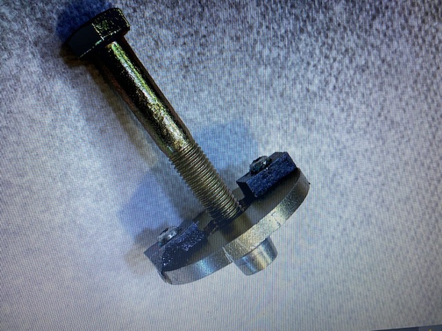
The rotating part (called the rotor) of the Boyer Bransden electronic ignition is threaded with a larger diameter thread than the end of the camshaft.
From memory it is a 5/16” UNF thread.
If you screw a bolt of this thread type into the rotor, it will push against the end of the camshaft and the rotor will drop off.
You may need to give it a very light tap just to break the seating on the taper.