
Hi
I've got to the stage of trying to separate the crankcases on my navigator. (I believe) I've removed all of the bolts etc holding them together - including the hidden ones - does the separation require pullers of any description (as someone has mentioned to me) or should they separate with a small amount of heat and persuasion? It's one of the original 'de lux' models 1960 and I would think the engine hasn't been split since it left the factory 60 years ago so it's being slightly stubborn. But for obvious reasons I don't want to 'push it'
Thanks in advance for any tips / help / guidance
Chris
Gently Does It
- Log in to post comments
When you say the hidden ones…
When you say the hidden ones, don't forget the one in the gearbox - of course you have the two hidden in the cylinder head sleeve holes.. I had similar issue and did not have them all out. Glad I checked before I got too keen.
- Log in to post comments
Hidden crankcase bolts in Lightweight motor
There are two 'hidden' bolts up top between the cylinders - and there are two more under the timing cover alongside the gearbox. There are NONE inside the gearbox - they are all external.
Sorry - I just noticed this thread is 6months old, and has wheel/spoke discussion in the middle. The NOC computer must be having an off day....
- Log in to post comments
What you need is a steady…
What you need is a steady pressure between the case halves while you heat around the bearing housings and bump the case mouths appart using a softwood drift and mallet. I have not have had to resort to wedges but have had to fill the bruising caused by clumsy use of metal wedges.Its also likely that the bearings are too tight a fit to the shafts , so heating around the cases may allow the bearings to come out of the cases. Shafts can be eased a bit for re-assembly.
- Log in to post comments
Separating crankcases
Hi Chris,
If you get a good quality kitchen knife with a sharp blade. I bought one from Ikea about 3 ins blade. The wife wouldn't let me use her Sabatier knife.
Find a likely place like the rear of the crankcases or near sump, put the sharp edge into the joint, and tap the back of the blade with a light steel or copper hammer. Don't use force and just let the blade taper do the work. No levering. Move along as the gap develops.
Robert and John probably don't realise that the drive side roller bearing will separate without any resistance. The inner stays on the shaft and the outer stays in the crankcase.
Andrew has the right suggestion in that you may have left one of the fasteners in place. Have you removed the two cap screws deep in the timing chest alongside the gearbox wall? Hidden by the timing cover gasket. As well as the ones between the cylinder locations?
Good luck with this one.
Peter
- Log in to post comments
good navigator information
hello guys well soon I will be separating my set of crankcases normally I sit the left-hand side on my wooden made square bloc witch is made from four 1.1/2 thick mahogany by 6-inch across and six-inch square so you can sit on there and the crankshaft is free and does not touch anything and then you can work ok and normally heat the right-hand side with a good plumbers gas blowlamp so the ball timing side bearing come out with not much trouble but with the navigator, I suppose you do this operation from the other way round as it has a gearbox to consider so this leaves the gear cluster in situ after removing the clutch and drive side gear all in one with its twin-row chain and then the drive sprocket which has a left-hand thread and warming the left-hand cases so the bearing do not give that much trouble, and my navigator engine as a mystery problem as when I bought it I was told it was a Seized engine but after removing the primary cover and getting out a spanner and trying to turn the engine over it was free to a point were you could only turn it over about 2/3 thirds of the way and it then stopped would not turn any farther then after removing the rocker covers and checked the valves were operating they were all ok so its not that so next is to remove the cylinder heads and investagate even more into this problem and the other problem I have is finding a rear wheel rim to the right spoke pattern as centeral wheels are convinced the rear wheel are 19 inch and 40 holes where I count 36 holes and a 18 inch rear wheel rim, or sould I tell them is a Francis Barnett rear wheel rim intead cannot any put so light on this , yours Anna J
- Log in to post comments
Anna, My 1964 standard…
Anna, My 1964 standard Navigator rear wheel has 36 holes and is 18" dia I have a photo of the wheel before the rebuild if you need it for reference also I can let you have a copy of my drawing of the wheel offsets.
As to Central Wheels, I found them helpful and even got a bigger discount for being a member of the NOC and VMCC, quality of the rim and spokes are also good, must be down to the person you deal with.
Steve
- Log in to post comments
thank you steve
hello, steve yes that would be really helpful contact me at annajeannette@btinternet.com or phone me if you like too at 01430 430 831 anytime for a chat
- Log in to post comments
I would not trust Central…
I would not trust Central to have the correct information .
- Log in to post comments
central wheel
hello rob yes that's what I found and they same to be a bit arrogant too like they know better then you that ownes the bike in question, your anna j
- Log in to post comments
Interesting that the 1964…
Interesting that the 1964 parts manual shows different part numbers for the rear rim between 250 & 350 although the spokes are the same part number & qty (36). Maybe a WM3 instead of the WM2 for 250 - or maybe lock bolt holes for the 350?
Bruce
- Log in to post comments
Wheel rims 250 and 350
Hi Bruce,
A knowledgeable friend of mine, Peter Fairbank, also very observant, notes that the Jubilee wheel rim carries the warning that this rim only suitable for up to 250cc. The Navigator rim carries no such warning. No lock bolt holes or WM3 either.
Hence the different part numbers.
I would not like to guess other differences between the rims which warrant the warning, but it explains the different part numbers for very similar 18inch, 36 spoke, chrome, WM2 rims.
Cheers
Peter
- Log in to post comments
Ahh, that answers that one -…
Ahh, that answers that one - thanks Peter
Bruce
- Log in to post comments
If you are not positive in…
If you are not positive in business then you fail. Does not mean you are always right though.
- Log in to post comments
yes your right
hello, rob yes your dead right with this one as SG as found out to his cost, his now in admin
- Log in to post comments
Splitting the crankcases
Sorry to come late to the party.
Chris - did you separate your crankcase halves succesfully?
When you undo all the visible bolts and screws, there are 4 more to find. Two are in the timing case along the gearbox wall, & you need a very long Allen key to reach them - and there are 2 more between the cylinders - which are fiddly to remove.
Once they are all out, the drive side case should come off first. Make sure the conrods are at BDC. You can try to coax it with wood and a mallet, between the cylinders, back of gearbox & sump - or (if strong) try to thump the engine sharply down onto a solid bench - or lump of wood - onto the alternator end of the crankshaft. If its 60yrs worth of gasket goo, then work it gentry with the mallet approach.
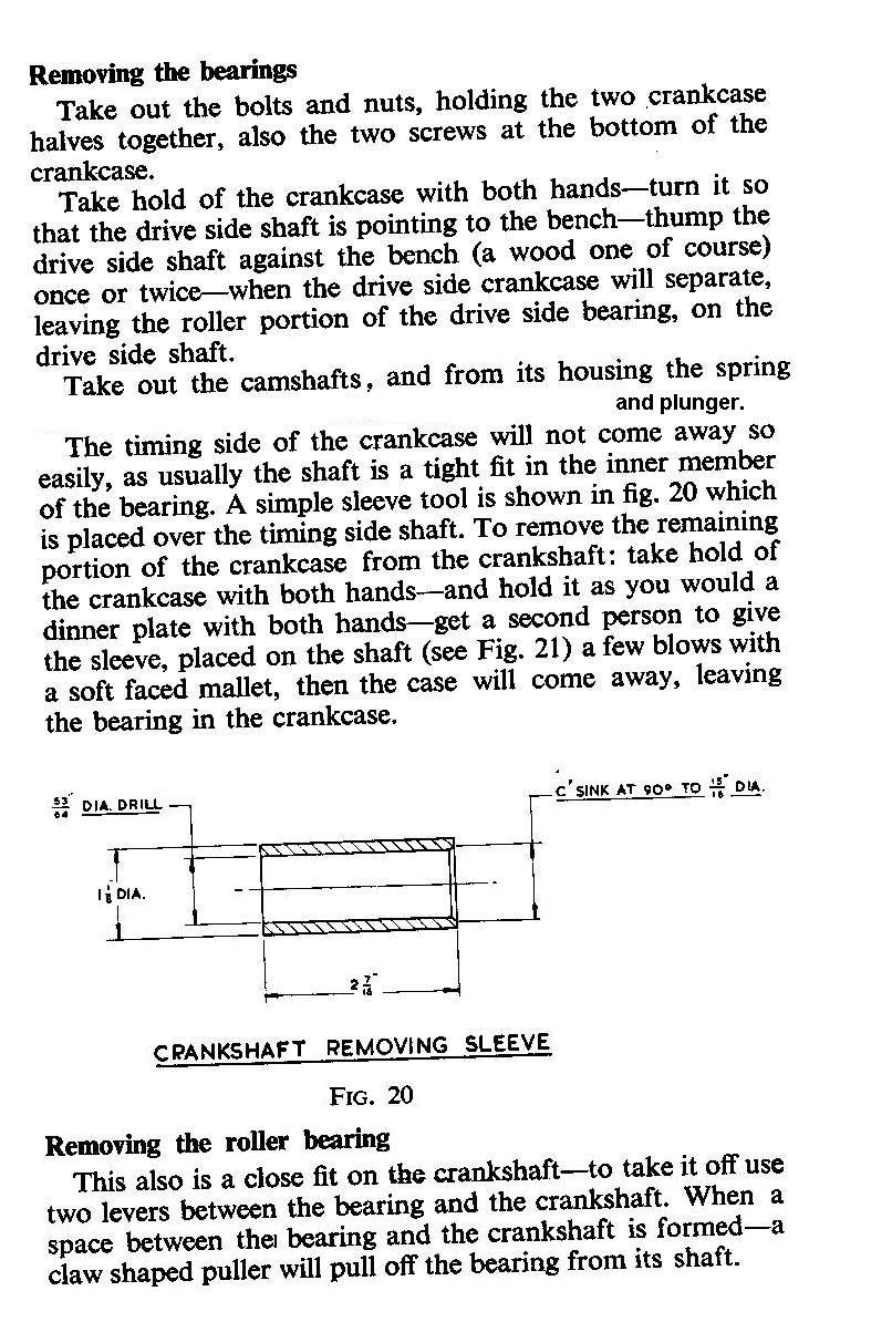
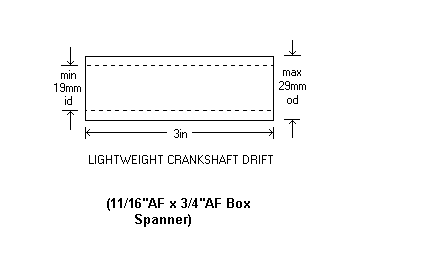
Once the drive side is off - then support the timing side case as best you can (I use old shelving & car axle stands) with the crank hanging down and lots of old towelling below to catch it. You then need a sleeve to pass over the oil feed end (you must NEVER hit the oil feed end) of the crank, such that it abuts the crank under the bearing. I have sacrificed an old AF box spanner for this task.
With everything in place, a sharp rap on the sleeve over the crank should suffice to dislodge it. Again, make sure the conrods are at BDC, so they do not catch.
- Log in to post comments
Oil pump gear
Hi Chris, you might be able to help me, I am stripping down my old Jubilee engine and am not sure about the thread for the oil pump drive gear on the end of the Crank shaft, is it a left hand thread or right is the question, I have attempted to undo it without success and it occurred to me that it might be a left hand thread so that it tightens with the rotation of the engine, I am assuming that you have removed yours and it is the same as the Navigator. Can you help please?
Howard
- Log in to post comments
Wedges and thread
In stripping my Electra engine I had to use wedges to lift the cylinder barrel which had been fitted with goo both sides of the gasket. I found Stanley knife blades were very useful for this.
I also tried them on the crankcase before I found the 2 long screws hidden near the gearbox/crankcase divider, and not mentioned in the manual. No damage was done as they are so thin it only displaced the gasket.
There was a question about the oil pump drive gear earlier. It is left hand thread.
- Log in to post comments


Over far to many years in mechanical maintenance I've split all kinds of casings, (gear boxes, motor covers, cylinder end plates, etc), many of which hadn't moved since leaving the factory. After checking that all bolts, screws, fasteners etc have been removed, (check then check then check again just to make sure), a tried and tested method is to use thin wedges lightly tapped in to the joint along its whole length. As you move along the joint you should find it starting to open up. Once it opens it will be necessary to keep the faces square to each other until the halves separate enough to clear any locating dowels. Gentle heat applied along the joint should release any sealing compound and lightly tapping with a hide (or rubber) mallet may help to loosen things up. Whatever method just be careful you don't crack the cases. Remember "softly, softly catchy monkey".
John