
I am aware that much has been written on this topic in the past but I have some specific queries which hopefully someone can assist with. I have a 1956 Dominator 88 but now bored out to 600cc which has always suffered from crankcase pressurisation and leaks to differing degrees after each rebuild. I have just discovered that the rotating breather plate on my bike appears to be different from the RGM and Norvil offerings in that the lugs which locate into the camshaft are at 90deg to the holes whereas the RGM/Norvil ones are at about 30deg. I cannot remember taking the fixed plate out to check the pin position relative to its holes but on a spare crankcase I have, the pin hole would be at 90deg to the vent holes as noted on my crankcase. I assume all crankcases were the same so the pin hole on my in use crankcase is likely(????) to be at 90 deg whichaccords with the new stationary plates available. I have attached a photo of the stationary plate in position, the rotating plate showing the relationship of lugs and holes is above the camshaft in the pic (spring sitting inside it). The end of the cam is also shown with its drive cut outs for the plate.
Questions
Is my cam, rotating and fixed plates all matched to open the breather at the correct time.
If not which of them is correct?
Will a correct match be obtained if I purchase a new rotating plate from RGM/Norvil?
I bought this as a box of bits and not everything was correct for the bike but these items looked ok. The cam, rotating plate and or stationary plate could be out of an earlier 88, Model 7, 77 or who knows what?
Any advise appreciated to finally eliminate this problem.
Thanks
Jonathan
Attachments
img_0035_new-pdf
The breather should open w…
- Log in to post comments
Just before the close of B…
Just before the close of Bracebridge factory, in 1963, the Dommi Twins timed breather was altered.
The ports changing from openings at three & nine oâclock to four & ten oâclock.
So there are two versions of the set-up.
- Log in to post comments
Previously Phil Hannam wro…
Previously Phil Hannam wrote:
Just before the close of Bracebridge factory, in 1963, the Dommi Twins timed breather was altered.
The ports changing from openings at three & nine oâclock to four & ten oâclock.
So there are two versions of the set-up.
Do you mean the holes in the static plate viewed from the left side of engine? (Not from inside the crankcase as in photo.)
- Log in to post comments
Previously Jonathan Soons…
Previously Jonathan Soons wrote:
The breather should open whenever the pistons are on the way down so every 180 degrees of camshaft rotation and for a duration of 90 degrees camshaft so the arrangement in your photo looks right to me.
The holes in the rotating plate are in-line horizontally at every TDC and the slots in the static plate are just getting uncovered.
Thanks for your reply Jonathan.
Do you mean my assembly would present the holes in the rotating plate horizontal at TDC or that's the way it should be?
The camshaft rotates clockwise looking from the RHS and the static plate holes sit diametrically from 1 o'clock to 7 o'clock so if the rotating plate holes are horizontal at TDC then the breather is closed as the Pistons move downwards until about 90 deg rotation when the holes start to line up and open. That doesn't seem right? Thoughts?
Sorry, I am wrong about camshaft rotation it is rotating anti-clockwise of course. Looks like from a horiz position mine would just be starting to open!
- Log in to post comments
Previously Phil Hannam wro…
Previously Phil Hannam wrote:
Just before the close of Bracebridge factory, in 1963, the Dommi Twins timed breather was altered.
The ports changing from openings at three & nine oâclock to four & ten oâclock.
So there are two versions of the set-up.
Do you know which mine is Phil? Is it a mixture of the two perhaps?
- Log in to post comments
Hi Jon...I have the later…
Hi Jon...I have the later timing disc in my early 500 Dommi engine which I also noticed had different timing but as Phil said above and Roy Bacon in his restoration book this was changed. My old disc was mutilated so I had to use the new version, but after reading this was a later mod felt comfortable with it. In my case, the engine has been so far absolutely oil tight so the new disc must be working OK. The only problem with my engine is that the wet sumping oil gets pumped out of the breather if it has collected but I'm sure it would do this with the old disc fitted too.
I can only assume the late timing allows just enough pressure to build up so that when it does there is a definite spurt of positive pressure out from the breather, and just like valve timing, the slug of gas discharging due to momentum continues to exhaust as the piston rises. Another thing is that the actual opening period of the valve crankshaft wise is the width of the slot in degrees multiplied by x4* (cam runs at half engine speed)..not just when they are completely open in line. Should you wish to test the opening period you simply have to blow into the breather pipe and turn the engine and you will be able to sense by mouth pressure when the valve starts to open and then fully closes.
You have to remember that the engine is revving at most times from 2000 -5000RPM so the shot of expelled gas is traveling at some force, but I have also to say there should be a partial vacuum created as long as there isn't too much blow by past the pistons.
One way to check if a breather is working correctly is to very gently and slowly block the outlet with your finger tip. Although you might feel pulses you should also feel a vacuum develop rather than have it continually blow your finger off the pipe.
Les
* See later reply.
- Log in to post comments
Previously les_howard wrot…
Previously les_howard wrote:
Another thing is that the actual opening period of the valve is the width of the slot in degrees...
Les
It is actually width of rotating slot PLUS width of static slot. Remember the slot rotates past another slot not past a line.
- Log in to post comments
Previously jon_osborne wro…
Previously jon_osborne wrote:
Do you mean my assembly would present the holes in the rotating plate horizontal at TDC or that's the way it should be?
Yours looks correct. The driving slots in the end of the camshaft are always vertical at TDC so the plate slots are horizontal. I have only ever seen one kind so Phil or Les will tell you if yours is preferred or upgradable.
- Log in to post comments
You are quite correct Jona…
You are quite correct Jonathon...Thanks.
So it is the width of the slot in degrees X4 to get the equivalent crankshaft rotating angle.
Assuming the static crankcase slots have the same width slots as the breather discs.....and they do pretty well...
Les
PS Changed previous post to amend this detail.
- Log in to post comments
Previously les_howard wrot…
Previously les_howard wrote:
You are quite correct Jonathon...Thanks.
So it is the width of the slot in degrees X4 to get the equivalent crankshaft rotating angle.
Assuming the static crankcase slots have the same width slots as the breather discs.....and they do pretty well...
Les
PS Changed previous post to amend this detail.
Have you noticed any discernible difference between the two types as I could opt for the new one if we think it better?
- Log in to post comments
Hi Jon...Unfortunately my…
Hi Jon...Unfortunately my M7 was a complete wreck when I bought it so I never had it running. As said above I noticed the different timing ports and phoned Roger at RGM who simply told me this was the revised timing. Would it be possible to supply the timing figures this new one creates and also the old ones, I certainly would be interested. I can remember them to be quite different. If not in degrees, piston position from TDC. I would like to be reminded to see if this does make mechanical sense. Simply blowing into the breather pipe allows an easy indication of the full opening period
The timing disc as said above was changed in 1964 but was the pipe breather pipe length changed at this time too??? *This might explain the need to change the timing due to the longer pipes natural resonance and inertia. If this is the case the I would imagine the original timing disc should be used with the short open pipe of the early engines...If this is so, I am quite annoyed as I have perhaps not the most suitable disc installed....now too late to change it.
Fortunately, as also said before, the engine is ABSOLUTELY oil tight so it must be breathing OK. Perhaps you need more feedback from other members to give you full confidence to use this later type disc....
Les
* Roy Bacon sates that the breather did not change from 1949-1971 (apart from the change of disc in 1964) but then right next to this there is a photo of a 1967 Atlas engine with a long length of rubber tube coming directly out of the front of the crankcase ....this is confusing.
Les
- Log in to post comments
I'm sorry I have had to d…
I'm sorry I have had to delete the message I had written here as I have just realised that I was looking at the static disc's timing holes and forgetting the cam shaft is turning the moving disc anticlockwise. For some reason I was looking at the photo and picturing the disc moving clockwise...So no help whatsoever...my appologies for the misleading info. So the best way to check is to use the blowing technique on a part assembled engine to really know the timing and duration angles for both old and new discs....Any volunteers???
Les
Attachments
24301.jpg
- Log in to post comments
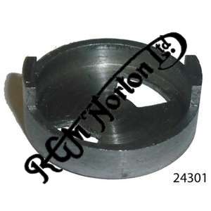
Attachment shows my collec…
Attachment shows my collection of 2 Model 7 Timing valves and 2 strangers with completely different slot positions. The 2 on the left are from the Model 7 engine and clearly show the 3 & 9 o'clock openings relative to the valve dogs.
Attachments
timing-valves-jpg
- Log in to post comments
Previously les_howard wrot…
Previously les_howard wrote:
Hi Jon...Unfortunately my M7 was a complete wreck when I bought it so I never had it running. As said above I noticed the different timing ports and phoned Roger at RGM who simply told me this was the revised timing. Would it be possible to supply the timing figures this new one creates and also the old ones, I certainly would be interested. I can remember them to be quite different. If not in degrees, piston position from TDC. I would like to be reminded to see if this does make mechanical sense. Simply blowing into the breather pipe allows an easy indication of the full opening period
The timing disc as said above was changed in 1964 but was the pipe breather pipe length changed at this time too??? *This might explain the need to change the timing due to the longer pipes natural resonance and inertia. If this is the case the I would imagine the original timing disc should be used with the short open pipe of the early engines...If this is so, I am quite annoyed as I have perhaps not the most suitable disc installed....now too late to change it.
Fortunately, as also said before, the engine is ABSOLUTELY oil tight so it must be breathing OK. Perhaps you need more feedback from other members to give you full confidence to use this later type disc....
Les
* Roy Bacon sates that the breather did not change from 1949-1971 (apart from the change of disc in 1964) but then right next to this there is a photo of a 1967 Atlas engine with a long length of rubber tube coming directly out of the front of the crankcase
....this is confusing.
Les
From the above info and assuming the rotating disc holes cover about 45 deg each, then my current disc would have the vent opening from TDC and would have closed around BDC. Apparently no pressure would thus be able to build up. With the new type, the crank would be around halfway down before the vent starts opening so some pressure would have built up before opening. Much as you said in your 1st response Les
I am currently feeding the breather pipe to the oil tank which, I believe, came in early 1960s. Perhaps I should vent directly to atmos
Jonathan
- Log in to post comments
Hello again Jonathon....yo…
Hello again Jonathon....your reminder of the revised breather disc had started to worry me. So I've been doing some investigations. First I started the bike and felt how much gas was being pumped out which surprised me as I would have thought after a few seconds of running it would taper off as a partial vacuum might be created but there was quite an amount of gas chuffing out. However putting my finger on the pipe to lightly seal the end did not create a high pressure indicating hopefully there is not much blow-by past the piston rings. Most of this gas or air it would seem is being taken back in via the breather....This worried me as it now seemed that the breather was perhaps opening half way down the bore stroke and closing half way up....OOOOOH Dear.
Anyway I thought I had better test the opening period by blowing in the breather pipe (now extended with a longer plastic pipe to allow mouth access)
By blowing in and releasing I found I could determine when the valve was open and when it was closed. I removed the plugs and put the bike in top gear so I could slowly turn the engine back or forwards by turning the rear wheel..... By repeated experiment, I found that the valve was opening about 5mm BTDC and about the same 5mm ABDC so a period of possibly something like 190-200 deg of crank rotation but it was happening at the right place.....perfect!
So just, like induction valve timing, the set up opens just before TDC and closes a little way after bottom dead centre. This will ensure good evacuation at high revs which is where you need it because there is likely to be more piston blow-by when the engine is producing more power (higher combustion pressure).
This observed timing will also explain why, at tickover, there is quite a bit of breather chuffing because the late closing of the disc valve will draw back a modicom of air which is then blown straight back out (actually venting the crankcase very nicely) . I did notice that revving the engine actually decreased the amount of gas blowing out which is explained by the inertial effect of the gas being blown out of a tube.
So to recap...I have the old 500 twin with the late modified breather disc working with the standard stationary crankcase disc...I Hope my findings can be repeated with your engine.....
Les
PS...I would love to know what the breather timing is with the old original disc fitted....can anyone help with this please?
- Log in to post comments
Previously les_howard wrot…
Previously les_howard wrote:
Hello again Jonathon....your reminder of the revised breather disc had started to worry me. So I've been doing some investigations. First I started the bike and felt how much gas was being pumped out which surprised me as I would have thought after a few seconds of running it would taper off as a partial vacuum might be created but there was quite an amount of gas chuffing out. However putting my finger on the pipe to lightly seal the end did not create a high pressure indicating hopefully there is not much blow-by past the piston rings. Most of this gas or air it would seem is being taken back in via the breather....This worried me as it now seemed that the breather was perhaps opening half way down the bore stroke and closing half way up....OOOOOH Dear.
Anyway I thought I had better test the opening period by blowing in the breather pipe (now extended with a longer plastic pipe to allow mouth access)
By blowing in and releasing I found I could determine when the valve was open and when it was closed. I removed the plugs and put the bike in top gear so I could slowly turn the engine back or forwards by turning the rear wheel..... By repeated experiment, I found that the valve was opening about 5mm BTDC and about the same 5mm ABDC so a period of possibly something like 190-200 deg of crank rotation but it was happening at the right place.....perfect!
So just, like induction valve timing, the set up opens just before TDC and closes a little way after bottom dead centre. This will ensure good evacuation at high revs which is where you need it because this there will be more piston blow-by when the engine is producing more power (higher gas pressure).
This observed timing will also explain why, at tickover, there is quite a bit of breather chuffing because the late closing of the disc valve will draw back a modicom of air which is then blown straight back out (actually venting the crankcase very nicely) . I did notice that revving the engine actually decreased the amount of gas blowing out which is explained by the inertial effect of the gas being blown out of a tube.
So to recap...I have the old 500 twin with the late modified breather disc working with the standard stationary crankcase disc...I Hope my findings can be repeated with your engine.....
Les
PS...I would love to know what the breather timing is with the old original disc fitted....can anyone help with this please?
Thanks Les, I'll check mine tomorrow
Jonathan
- Log in to post comments
Previously jon_osborne wro…
Previously jon_osborne wrote:
Previously les_howard wrote:
Hello again Jonathon....your reminder of the revised breather disc had started to worry me. So I've been doing some investigations. First I started the bike and felt how much gas was being pumped out which surprised me as I would have thought after a few seconds of running it would taper off as a partial vacuum might be created but there was quite an amount of gas chuffing out. However putting my finger on the pipe to lightly seal the end did not create a high pressure indicating hopefully there is not much blow-by past the piston rings. Most of this gas or air it would seem is being taken back in via the breather....This worried me as it now seemed that the breather was perhaps opening half way down the bore stroke and closing half way up....OOOOOH Dear.
Anyway I thought I had better test the opening period by blowing in the breather pipe (now extended with a longer plastic pipe to allow mouth access)
By blowing in and releasing I found I could determine when the valve was open and when it was closed. I removed the plugs and put the bike in top gear so I could slowly turn the engine back or forwards by turning the rear wheel..... By repeated experiment, I found that the valve was opening about 5mm BTDC and about the same 5mm ABDC so a period of possibly something like 190-200 deg of crank rotation but it was happening at the right place.....perfect!
So just, like induction valve timing, the set up opens just before TDC and closes a little way after bottom dead centre. This will ensure good evacuation at high revs which is where you need it because this there will be more piston blow-by when the engine is producing more power (higher gas pressure).
This observed timing will also explain why, at tickover, there is quite a bit of breather chuffing because the late closing of the disc valve will draw back a modicom of air which is then blown straight back out (actually venting the crankcase very nicely) . I did notice that revving the engine actually decreased the amount of gas blowing out which is explained by the inertial effect of the gas being blown out of a tube.
So to recap...I have the old 500 twin with the late modified breather disc working with the standard stationary crankcase disc...I Hope my findings can be repeated with your engine.....
Les
PS...I would love to know what the breather timing is with the old original disc fitted....can anyone help with this please?
Thanks Les, I'll check mine tomorrow
Jonathan
Sorry Les, I got involved in an extended plumbing job yesterday.
I have now checked the opening of the breather on my bike which has the original disc fitted (3 and 9 o'clock type)
My dial gauge only covers the first couple of mm of travel so not much use. My figures using pen and paintbrush are a bit rough but I think it serves to indicate the difference.
Opening appears to start around 15mm BTDC and appears to be closed at BDC. From my calculation this means mine opens around 55Deg BTDC and is closed at BDC - the point of highest pressure!
With a 5mm BTDC opening yours appears to open at 30deg BTDC and closes 30Deg ABDC which sounds quite good. Looks like the new type is the way to go!
As a matter of interest I wrote an article about breather problems and testingon my engine in Roadholder 314 'More Breathers, Digest and Discuss' in which I show and discuss the oscilloscope traces at tickover and mid range of crankcase pressure.The traces made little sense but I will review them in light of the above .
Jonathan
- Log in to post comments
Well done Jonathon and tha…
Well done Jonathon and thanks for taking the trouble to test the old disc. Like yourself, and perhaps not even as good, my stated positions of the piston have not been recorded at extreme accuracy. After reading of your concern the alarm bells rang so I did the test to get some reassurance that the new disc (the only type you can buy nowadays it seems) was not way out, for example, opening when the piston was going upwards and closing on the down-stroke...Thankfully, it seems the new timing makes a lot of sense.
As my engine is assembled sensing the opening period by blowing is a touch difficult simply because within a second the air pressure being blown in rises but I could get a rough idea by blowing and releasing alternately....any air movement indicates the valve is open...When the valve is closed, obviously no air is admitted at all and you can sense the difference. ....However I thought of a much better method:
If a long transparent plastic tube was run from the breather pipe to drop vertically into a bottle of water the movement of water in the tube (there will be air bubbles blown out initially) will provide a very precise indicator of the valve doing its job of opening and closing. Measuring the piston position with a stick in the plug hole is sufficient and probably accurate to + or -1mm...This can be converted to crank angles easily enough if required.
I don't have the Roadholder mag No 314 but would love to read it, I think it would be very interesting...I'm sure others would find the exact findings for both discs very interesting too....although I realise this might be boring for some, but they can just ignore it should they choose...Many thanks again
PS... if you have the time, could you check again with the new disc to see if my findings are at least in the right ball park....no rush I appreciate you are busy...Thanks
Les
- Log in to post comments
Previously les_howard wrot…
Previously les_howard wrote:
Well done Jonathon and thanks for taking the trouble to test the old disc. Like yourself, and perhaps not even as good, my stated positions of the piston have not been recorded at extreme accuracy. After reading of your concern the alarm bells rang so I did the test to get some reassurance that the new disc (the only type you can buy nowadays it seems) was not way out, for example, opening when the piston was going upwards and closing on the down-stroke...Thankfully, it seems the new timing makes a lot of sense.
As my engine is assembled sensing the opening period by blowing is a touch difficult simply because within a second the air pressure being blown in rises but I could get a rough idea by blowing and releasing alternately....any air movement indicates the valve is open...When the valve is closed, obviously no air is admitted at all and you can sense the difference. ....However I thought of a much better method:
If a long transparent plastic tube was run from the breather pipe to drop vertically into a bottle of water the movement of water in the tube (there will be air bubbles blown out initially) will provide a very precise indicator of the valve doing its job of opening and closing. Measuring the piston position with a stick in the plug hole is sufficient and probably accurate to + or -1mm...This can be converted to crank angles easily enough if required.
I don't have the Roadholder mag No 314 but would love to read it, I think it would be very interesting...I'm sure others would find the exact findings for both discs very interesting too....although I realise this might be boring for some, but they can just ignore it should they choose...Many thanks again
PS... if you have the time, could you check again with the new disc to see if my findings are at least in the right ball park....no rush I appreciate you are busy...Thanks
Les
Thanks for your comments Les.
My bike is fully assembled and it will be some time before I have it rebuilt with the new type disc.
Roadholder 314 is available to view to all members on this site.
Not sure we can progress this further in the short term
Jonathan
- Log in to post comments
Well done, Les. I could ha…
Well done, Les. I could have done with you in the 3rd Form Physics Lab! George
- Log in to post comments
Thanks Jonathon for the "h…
Thanks Jonathon for the "heads up" on the Roadholder Magazine downloads, I never knew they were available.
Read your article but unfortunately it seems that the pressure sensor was fitted in the breather pipe, but this is not going to show the dynamic pressures inside the case.... It would be easy to fit a timing cover with the Tachometer cutout and make a plain plate to house the sensor....Another possibility is to fit the sensor on one of the rocker box covers as there is a link between the push rod tunnels and the crankcase but slightly restricted (I think) so might not accurately track the pressure variations ...but might be OK...
Hi George....yes did A level physics and always pleased to help..
Les
- Log in to post comments
Previously les_howard wrot…
Previously les_howard wrote:
Thanks Jonathon for the "heads up" on the Roadholder Magazine downloads, I never knew they were available.
Read your article but unfortunately it seems that the pressure sensor was fitted in the breather pipe, but this is not going to show the dynamic pressures inside the case.... It would be easy to fit a timing cover with the Tachometer cutout and make a plain plate to house the sensor....Another possibility is to fit the sensor on one of the rocker box covers as there is a link between the push rod tunnels and the crankcase but slightly restricted (I think) so might not accurately track the pressure variations ...but might be OK...
Hi George....yes did A level physics and always pleased to help..
Les
I agree Les, but it was the only tapping I had so I thought I would give it a try. Some interesting traces though. I guess the way to go is with the timing cover as it is well connected to the crankcase but I didn't have a spare cover to modify.
Jonathan
- Log in to post comments


The breather should open whenever the pistons are on the way down so every 180 degrees of camshaft rotation and for a duration of 90 degrees camshaft so the arrangement in your photo looks right to me.
The holes in the rotating plate are in-line horizontally at every TDC and the slots in the static plate are just getting uncovered.