
Hi all,
My resto continues at speed - I've just started on the primary drive with an RGM belt drive kit.
I did not remove the original primary, so don't have the advantage of how it all came apart - rather a box of various bits.
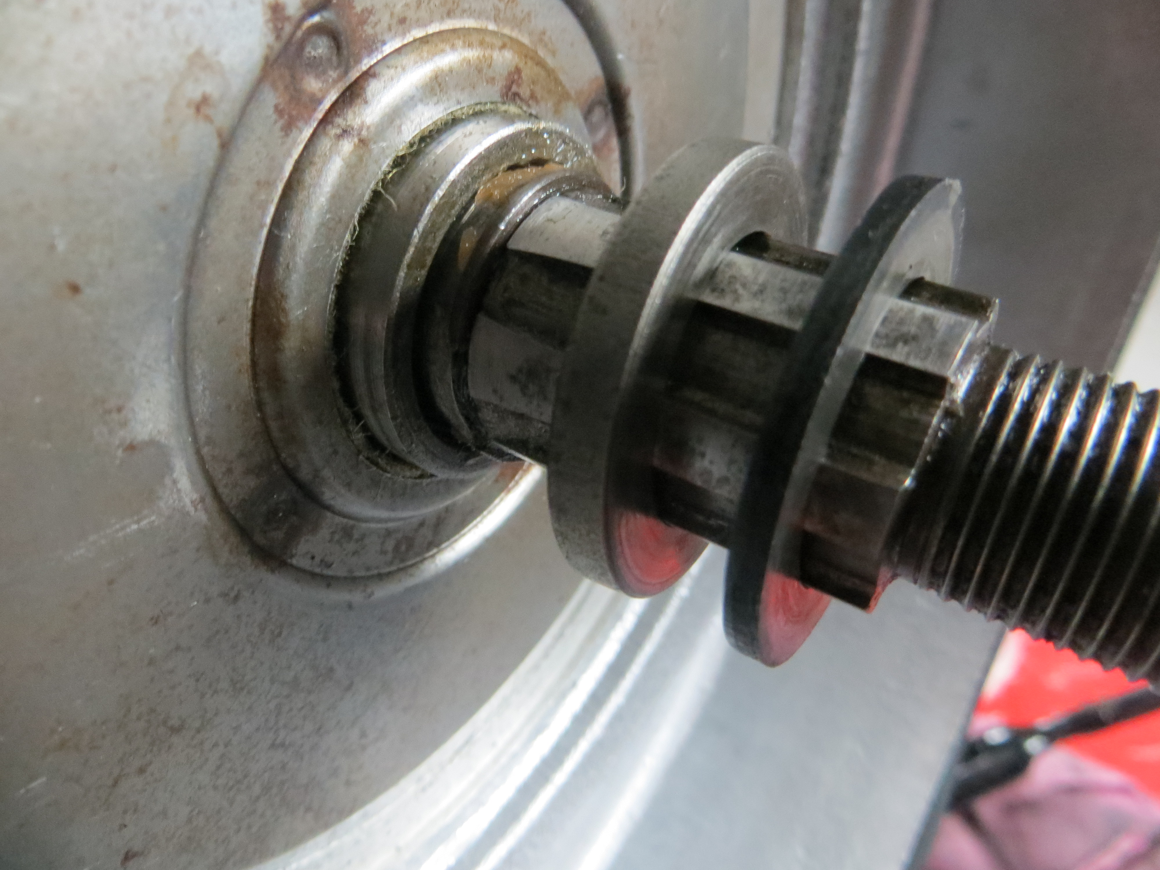
First issue - the main drive shaft from the gear box protrudes into the inner primary cover with the shaft and exposes a C clip on the shaft with a gap to the back of the primary case. Is this correct? It occurs to me that when I place the spacers (x2) on the shaft, then the clutch basket, assemble the plates and tighten the outer nut, it will all bear down on the C clip - is that right?
Also what's the order of the spacers - I have one plain of 0.090'' thickness and one of 0.168'' thickness (which has an internal step on one side only)?
Second issue - the charging rota has a key way which is smaller than the key way on the crank shaft - do I just have the wrong rota? Are there various sizes? I don't have the original rota to check.
Photos attached of issue 1.
Thanks for any help. Paul.
Primary Drive Assembly
- Log in to post comments
Primary drive
Hi
I agree with Richards comments above and would add i was advised to torque the clutch nut to 45 ft/lb and lock tight it. I had to remove it 2 days later which took mode effort than i thought.
I assume you are using a parts manual, i have pictures taken when i stripped my standard Commando happy to send any pictures you want via WhatsApp.
- Log in to post comments
Felt washer?
You mention a 'gap to the back of the primary case', in connection with the mainshaft – there should be a felt washer in the sliding plates fitted to the inner primary case, if it's missing there'll be a gap – is that the gap you mean? Just wondering.
- Log in to post comments
All, Thanks for the…
All,
Thanks for the comments very useful.
So issue 1 is resolved - that's how its meant to look and go back together - great thanks. (yes Colin - I have the felt washer in the sliding pate).
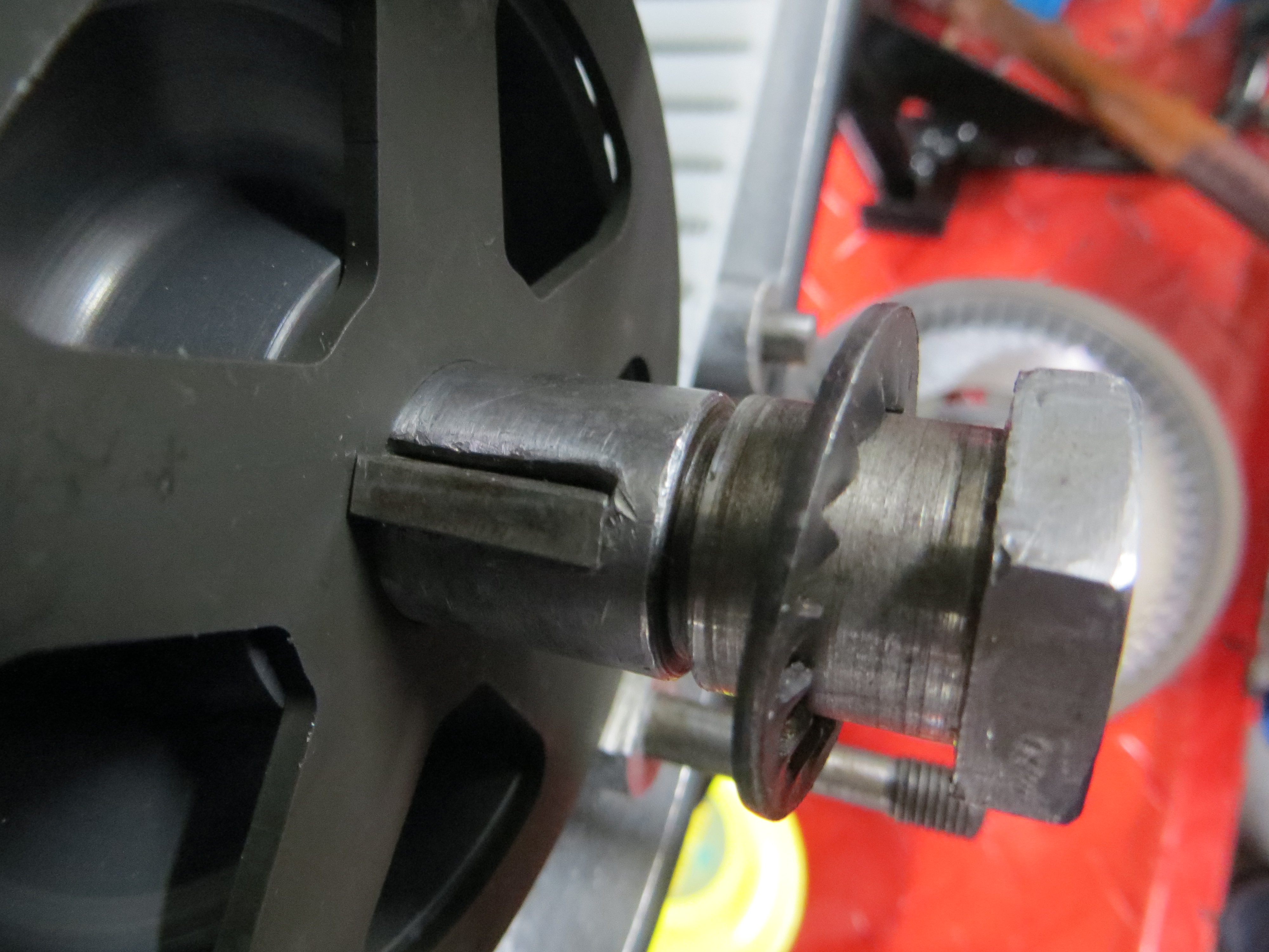
When I look and measure the crank key way, the key and rota...
Key and rota match at 0.158'' and 0.159'' - the key slides in the rota snug.
The crank key way is the issue - at the bottom of the key way 0.161'' but at the top 0.198'' and the key when placed in the crank key way rocks from side to side.
So it looks like the rota has become loose on the shaft and worried the crank key way making it now a sloppy fit for the key.
Is this something to worry about - or just get it tight to the correct settings and it will be OK?
Attached photo of the key in the crank shaft key way slot - I pushed the key to the left, you can see the 0.030'' plus gap on the right hand side.
Thanks - Paul.
- Log in to post comments
Keyway
Sorry Paul, I missed that you'd posted a photo, in which the felt washer can clearly be seen! That keyway though, ow! I've no experience with that kind of issue, but maybe you could make up a key, 'stepped' so it's thick enough for the keyway but thin enough for the rotor? Or make up a shim to take up the gap in the keyway? I expect someone's had experience of this though, and might have a better idea … I'd be very worried about the rotor hammering again if I just did it up and hoped for the best. I can't remember what the manual says about that shake-proof washer (or if it says anything at all), but from memory I've replaced it frequently – I'm not sure how effective it is when re-used, anyway. HTH
- Log in to post comments
Key way...
Thanks Colin - yes I have a new washer ready to use.
I like the idea of making a specific key that fits the worn key way - is that the best way forward?
I guess the timing using a strobe on the degree disk primary cover could not be relied upon, as the marks on the rota may be out a bit - that can be resolved using a timing disk instead.
Thanks - Paul.
- Log in to post comments
Timing
You're probably aware that the degree marker inside the primary cover is unreliable anyway …? Unless it's checked and then left undisturbed. Twenty years or so ago I installed a 180 Watt alternator on my MK2A and found that the new rotor interfered with the degree marker, so I ditched that and scribed suitable marks in the resin of the stator instead, it works!
- Log in to post comments
I have a home made stepped…
I have a home made stepped key on my Dommie shaft with no problems. The crank slot widened out because the bike arrived without the correct split washer below the rotor fixing nut, and the rotor came loose, and started to rock about. In doing so, it made a horrible noise and destroyed the stator. You don't want that! It's given no trouble ever since.
If the key is not snug, it's bound to loosen the nut eventually.
- Log in to post comments
Just a thought here but why…
Just a thought here but why not order another woodruff key and grind it down till it fits the slot. Sort the timing with the bike running.
- Log in to post comments
Thanks again all. I also…
Thanks again all.
I also asked Norman White about the issue and post his response, as I expect this will be useful to more than a few of us....
Hi Paul. I take it that is the gen. rotor keyway. Not much to worry about as it is there to position the rotor correctly to aid strobing the ignition. What you must do for accuracy when timing is to do what I do with bikes that I have not seen before, and that is to check and correct the degree plate inside the outer c/case. You need a degree disc and attach it to the crank in such a way you can release it without allowing the crank to turn. Fit the key and rotor and torque it up with a little locktite. Find TDC with a dti or bar set so you can rotate engine forward and back to split the reading. Set the d/disc to TDC and rotate backwards to find 31 deg. or 28 depending on ignition system. Don't forget to rotate forward to the 31 or 28. Then take off the disc without allowing the engine to rotate and bolt the outer case on. Then check the timing mark line on the rotor against the degree plate and you can then adjust the deg. plate if it is screwed in place or if riveted, scribe your own mark to coincide with the line so you can use the scribe mark to time to.
Regards,Norman.
- Log in to post comments


The 'internal step' goes over the circlip and prevents it from being squeezed out...there are suggestions that the quoted torque figure is too high and that a new clip should be used each time. I've never actually had a problem.
Rotor keyway should match the rotor - Can you measure either / both ? Has someone machined out a damaged crank keyway. A stepped key could be used...but it must be correct or you can't use the timing marks.