
I know have my new Stator and Rotor fitted and duly measured the Air Gap ( min of 0.0008"). It is quite `tight `at this measurement and even more so on one side. I have rotated the crank and still find a `Tight side`. There doesn`t appear to be any way of adjusting things as the Stator is held steady in the Stator housing with only slight Rotation on the mounting studs for any movement. Am I being too picky ? What do you blokes think ? 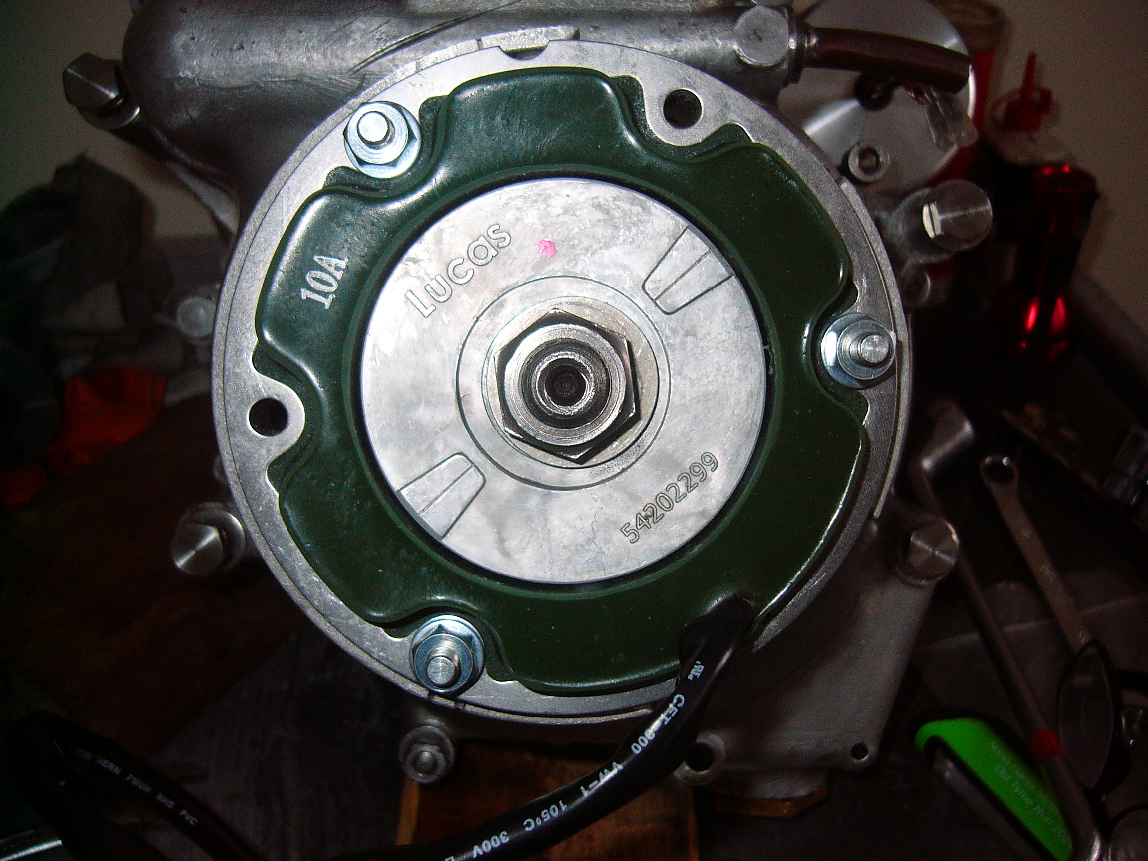
There's usually...
- Log in to post comments
Feeler gauge strips
I think the original instructions were to use feeler gauge strips around the perimeter of the rotor (when it has been fixed in position) and then bolt the stator on. There is no adjuster, as such, but the feelers should maintain the gap when you tighten the bolts. Many years ago I used to get the gauge strips from Vauxhall dealers, but you could use 3 feeler gauges - if you have them.
Dunno what thickness you are supposed to have as I haven't found the required air gap data yet.
- Log in to post comments
I hope you meant 0.008". …
I hope you meant 0.008". And that's a minimum gap, checked at all core ends, with crankshaft rotated right round 360 degrees.
There have been reports on https://www.accessnorton.com of Wassell's new "Lucas" stators burning out, which may be caused by lack of clearance leading to rubbing.
- Log in to post comments
This is the season for this…
This is the season for this hardy chestnut which I have responded to in the past and one that I have carried out myself.
I followed Norman Whites tip by reducing the retaining bolts down to their core diameter i.e. the bottom of the thread depth, the plain area behind the threads.
This allows plenty of leeway for adjustments to attain .008" using feeler gauges around the periphery of the rotor.
- Log in to post comments
Aluminium drinks can…
Has been my gauge of choice. No magnetic movement and easily cut with scissors. Of course keeping things imperial...., I always use "Inches" .
- Log in to post comments
stator/rotor air gap
Hve met this problem many times. I position 6 pieces of plastic milk bottle strips around the rotor before tightening the (slack) stator stud nuts. If still too tight, you can enlarge the stator holes slightly by careful filing. This has always worked for me and no burned out stators!
- Log in to post comments
Very careful.....
If you use this method for reducing the studs to get the clearance, then the stator might just move back! in which case you are worse off than when you started.
The following has been done BUT is to be done with a lot of care. You can file the inside of the stator BUT that would invalidate any guarantee. You could also invalidate any guarantee by turning a A FEW THOU off of the rotor.
PS Just be thankful you do NOT own an AJS/M!
- Log in to post comments
Embarassed to admit that i…
Embarassed to admit that i just give the studs a mild whack with a plastic faced hammer in the required direction . Has always worked for me-------.
- Log in to post comments
Done the same many times…
Done the same many times. Also alloy coke can makes a good gauge to wrap around the rotor.
- Log in to post comments
Wow , lots of suggestions…
Wow , lots of suggestions there ! I did actually mean 0.008" air gap . I still cant see that by making the studs thinner or the holes in the stator bigger it will allow any movement up or down as the whole Stator is held firmly by the Stator Housing which only allows minimal Rotational movement between the stator holes and the smaller mounting studs . To get any up or down movement it looks like the Stator Housing might need `shaving ` . Having said that the 0.008" feeler gauge is a tight fit most of the way around until it gets `very tight ` in one area. I have rotated carefully a few revolutions and no scraping marks have appeared on the Rotor so there is clearance.
- Log in to post comments
You have a clearance of…
You have a clearance of sorts but a clearance that is in an ambient atmosphere, the .008" is calculated for engine running temperature allowing for the expansion of the components involved.
- Log in to post comments
Coincidentally, only just…
Coincidentally, only just recently I was contacted by a chap who had just bought an 850 Commando with belt drive whereby he had to fettle something in this area having to take off the belt and such.
After replacing the components including the alternator side of things he was not aware of the .008" clearance required and after only a few miles of riding the bike the alternator expanded onto the rotor, you can guess the rest.
To remove the mess he had to resort to grinding the crankshaft sleeve nut off.
- Log in to post comments
air gap on stator.
call hitchcocks enfield they do an 8-thou clearance gauge for 2 quid wraps round stator job done.
- Log in to post comments
I'm not saying my opinion is…
I'm not saying my opinion is worth all that much, but I think that sounds like there isn't safe clearance there.
- Log in to post comments
Poorly Made Stators
In the past, I have often found that the Resin used to coat the Stator Windings had lumps poking out on the inside. This, in turn, has made getting a reasonable clearance all round the Rotor very difficult.
So I set up my Pillar Drill, with a flap wheel, and proceeded to smooth the inner finish of the Stator with a few seconds of rotary motion..
The Stator iron cores prevent the flap wheel from removing too much of the resin and I have never ever found bare wires showing afterwards.
- Log in to post comments
Some report using a PET…
Some report using a PET bottle (litre of lemonade or similar) to make a collar all the way round when tightening it all.
- Log in to post comments
The washers under the stator nuts
. . .seem to be reducing the possibility of moving the stator, jamming it in one position. This is how it looks to me from what I can see from the photos. Smaller washers may help, or alternatively I seem to recall obtaining reduced hex nuts from one of the major vendors, probably Norvil, for the stator on one of my Dommies many moons ago.
Those new Lucas/Wassell stators also have quite a bit of potting around the mounting holes which can be dremelled away to create more clearance, so long as you're careful.
- Log in to post comments
Just to make my problem…
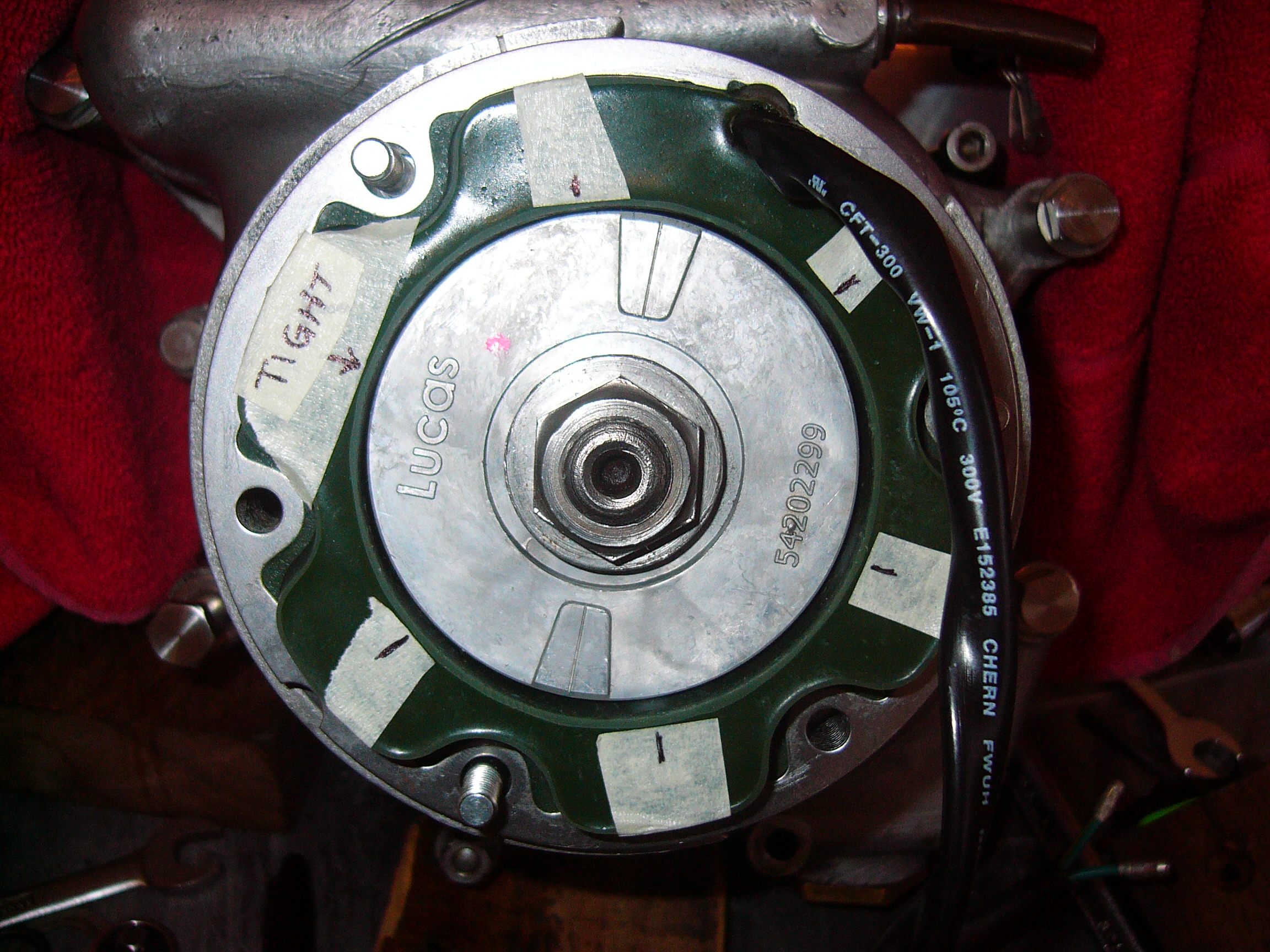
Just to make my problem clear I cannot get any movement up or down due to the Stator Holder being a tight fit on the Stator itself. This only allows Radial movement which doesn`t allow me to get `even clearance `between the Rotor and the Stator. Just having slimmer mounting studs , bigger holes in Stator or smaller washers /nuts only gives more Radial movement which makes no difference to clearance or centralising . I really cant see any other way of attaining the required adjustment other that relieving some alloy from the Stator Holder ! Photo shows hopefully how the stator fits so `snug` . The masking tape markers show where the pick ups are located. There is no high points on the Potting either .
- Log in to post comments
You have a number of…
You have a number of suggested options here in amongst the comments.
If you have access to a lathe this method will show up any discrepancies in the roundness of the stator or rotor for that matter and you then have a choice as to which component you need to machine.
Internal measuring of the bore of the stator at various points will seek out the high and low points also.
To test the rotor you can do it whilst bolted to the crankshaft and set up a pointer or DTI with or without the engine running, bare in mind that there may be a certain amount of crank run out which will certainly impact on the clearance.
The mention of a flapper wheel being used can be a quick fix if these suggestions are not a practical answer in your case. The marks you show on your stator should be enough to start the process.
- Log in to post comments
Thanks Paul . All duly noted…
Thanks Paul . All duly noted and a few things to check there . Will have to make a mounting `Boss` to fit into my small Lathe ! Got to admit Having bought all this stuff New I would have thought it would have gone together better than this . Surely when they were factory built they couldn`t have gone out the door like this ?
- Log in to post comments
Wayne - There is usually a…
Wayne - There is usually a gap between the outer of the stator and the lip of the stator holder. Your image shows a gap at the bottom but a tight fit at the top. So either the holder is misshaped or the stator isn't correct. If the bike was mine I would remove the stator and rotor and if the holder is well secured to the crankcase i would tap the top of the holder firmly outward and upwards until a gap is evident ( 1mm will be enough gap ). Then you should be able to set your rotor/stator gap using a toffee hammer in accordance with the waisted stator holder studs as someone has already mentioned. Good luck, Howard
- Log in to post comments
Howard - I did think of…
Howard - I did think of doing that but was worried that it might crack or even smash the casting ?
- Log in to post comments
They are stronger than they…
They are stronger than they look. Done it many times without breaking one. Cheers, Howard
- Log in to post comments
Hi Wayne, At the beginning…
Hi Wayne,
At the beginning of your post, you say you have fitted a new rotor and stator, then you find that there is insufficient clearance, and later you make it clear that this is not something you can adjust, so surely this item is not fit for purpose.
Have you gone back to your supplier and asked for their response?
If you bought a spare wheel for your car and the holes did not line up, you would not think for a moment about moving the holes. Why should new bits for an old motorcycle be any different?
Tony
- Log in to post comments
Not as yet Tony . Wanted to…
Not as yet Tony . Wanted to get some feedback first .
- Log in to post comments
Of course.......!
Of course they didn't come out of the factory like this!!! that was over 60yrs ago, Lucas who made the original stator/rotor have long gone and we are stuck with far Eastern parts 'similar' to what we used to have, you will also find there is negligible technical back up and understanding from Wassell so do NOT expect modern manufacture far Eastern parts to fit with out some fiddling OR you return it as Tony says-'NOT FIT FOR PURPOSE'
- Log in to post comments
Your two pictures show the…
Your two pictures show the stator in two different positions. Is the tight spot always at 10 o'clock or does it move around with the stator as you fit it in each of the three possible positions? If the tight spot doesn't move, it's the mounting plate.
- Log in to post comments
It looks like that to me too…
It looks like that to me too as it is always tight in on the same side /spot.
- Log in to post comments
Sorted ! Thanks to all for all your comments and advice.
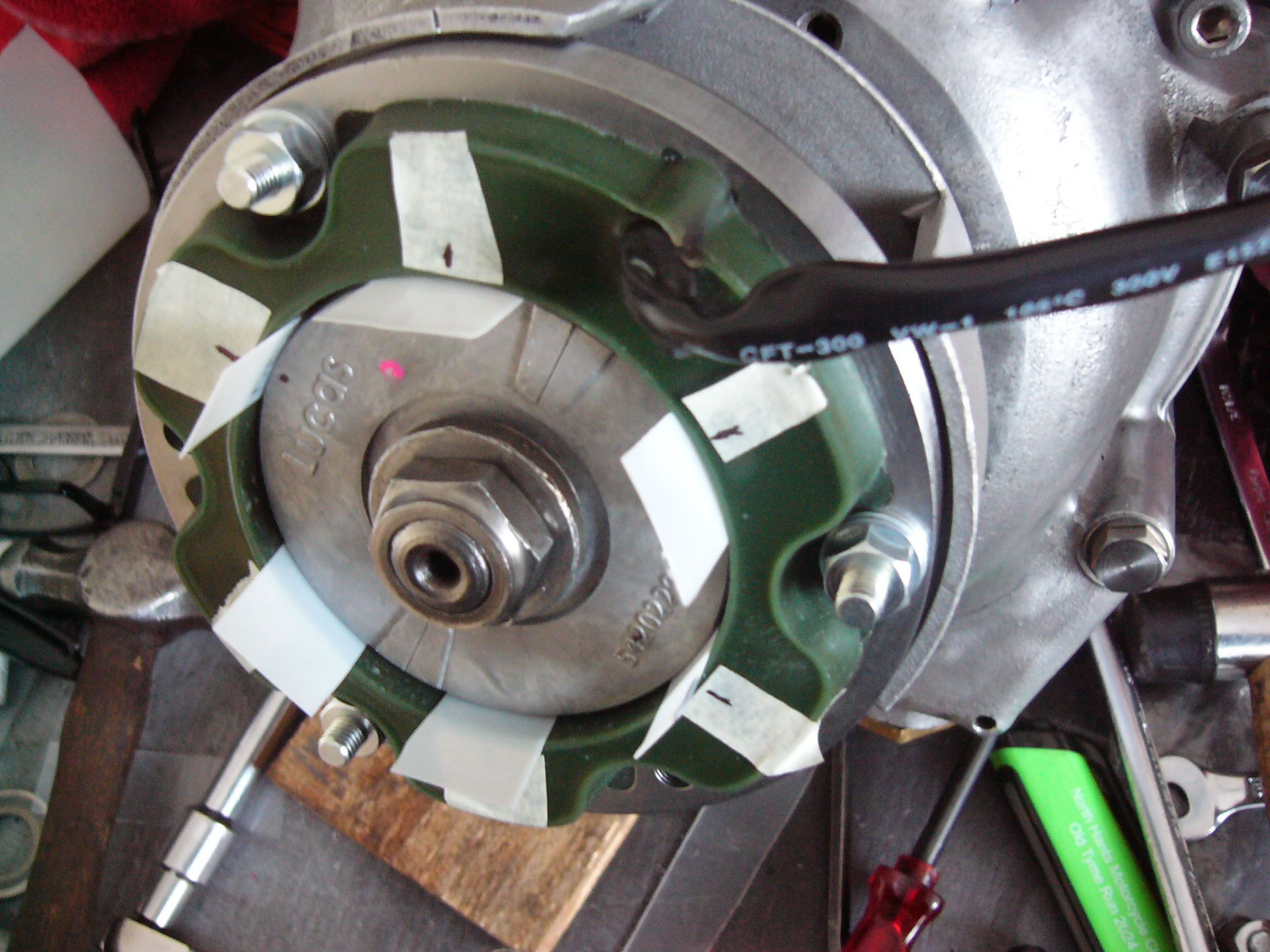
I decided that the only way to sort this was to get more `slack` for adjustment between The Stator holder and the stator itself. Managed to get it set up in my little lathe and slowly / gently remove enough material to allow the required clearance. I used the cut up plastic Milk bottle on a trial assembly which worked very well with a few taps here and there to make perfect. Attached Pic shows fitted Stator / Rotor with plastic strips on a trial fit .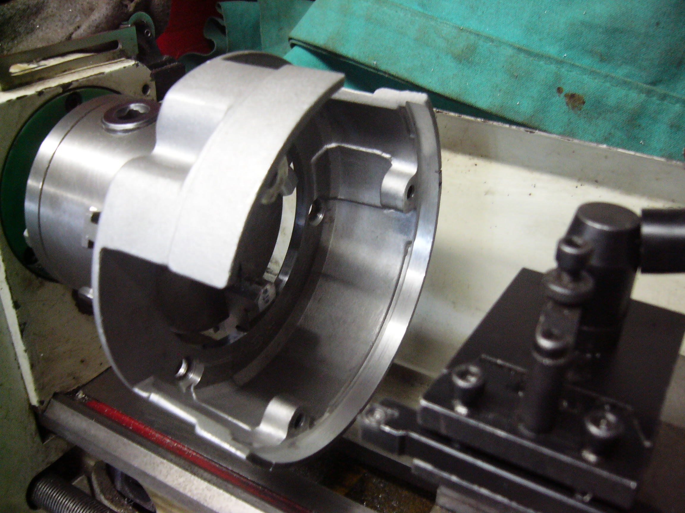
- Log in to post comments
A question for the tecchy…
A question for the tecchy guys, should the cable exit be as shown or out the back as mentioned in the dommy manual ? I know mine (out front ) is getting rubbed by the cover !! And are they new studs 1/4 into the ally and 5/16 thro the stator / ,perhaps you have re tapped the housing too?
- Log in to post comments


... a bit of clearance of the studs in the mounting holes and the stator can generally be persuaded into place. Leave the nuts just catching and give a gentle tap with a rubber hammer in the desired direction.