
Presumably this is a Velocette-style ball-and-spring arrangement. Am I correct in thinking that servicing/renewal is by removal of the small screw in the head of the banjo bolt? (see pix at
http://www.hollandnortonworks.eu/en/exclusive-commando-parts
Based on but not the same as…
- Log in to post comments
I see these are automatic in…
I see these are automatic in daily use - but not really automatic if they must be primed. What is the problem with a valve and built in switch? 'Make' or 'break' depending if it is magneto or coil ignition.
https://www.feked.com/anti-wet-sump-oil-pipe-tap-with-switch-magneto-or-coil-ignition-systems.html
...is one example, but there are others - including one for Singles with magnetos.
- Log in to post comments
They only...
... need to be primed when the oil line downstream has had air introduced - at least that's the case with the Velo one. When I had a Venom I used a syringe to make sure that line was full when changing the oil.
I've never heard of a Velocette valve failing.
- Log in to post comments
I also have a Venom …
… so the joys of priming the oil feed after disturbing it are familiar; I was slightly apprehensive about doing this earlier in the year, having acquired a Velo after nearly four decades without one, but in practice it was really no trouble at all (although I was of course relieved when oil emerged from the union on top of the timing case).
Like Ian, I've never heard of a Velo valve failing (in the sense we have in mind here) — something that would be surprising, since the design is intrinsically fail-safe as far as I can see.
The only discussion of these in Velo circles seems to be reminders that it is a fallacy to think that one can revive a failing valve by tapping the ball against its seat.
On enquiry to HNW they said that its purpose wasn't as I supposed (without saying what it was for), so John's suggestion that the small bolt is to aid in priming makes sense.
The tap-and-switch idea clearly makes sense, but (a) I'm averse to electrickery without clear benefit, (b) a completely automatic solution seems preferable in principle, and (c) the HNW version simply bolts straight in without further modification.
- Log in to post comments
Has anyone in the club…
Has anyone in the club fitted one of these?
Does it work?
- Log in to post comments
Yes, works well with no…
Yes, works well with no problems (so far!)
A good review of Commando aws valves on the Access Norton site, the HNW one comes out a clear winner.
However, some belt & braces recommended, 64psi on start up, 45 when hot :
- Log in to post comments
Fitted and tested one
I fitted one in april this year, no complaints so far.
According to Constant of HNW, the little screw was originally intended to prime the oil line.
But it is a tedious and slow process, so Constant advised to fill the line with oil through the banjo just prior to installing the valve.
Prior to mounting the valve, I did a little test to determine the opening and closing pressure.
I had the valve hanging upside down from a clear plastic hose and filled the hose slowly with water.
The valve opened at approx. 75 centimeter water column, so about 0,075 bar diff. pressure.
The valve than started closing again and after 15 minutes with approx. 40 centimeter water column, so about 0,04 bar diff. pressure, the level was almost steady.
After 8 hours, the level had dropped another half a centimeter: the valve was just about shut.
The real opening and closing pressures are probably about 15 % higher as the valve sits almost horizontal when installed in the tank, and the influence of the weight of the ball is gone.
The closing pressure seems OK considering the oil level in the tank is about 10 centimeters above the centre line of the valve.
I also tested the valve on the bench using weights on the ball. The result for the opening pressure was about the same.
Cheers, Bennie
- Log in to post comments
When I did my own version…
When I did my own version many years ago I reduced the spring tension until the column of oil it held back was 50cms high, it's the height not the volume of oil you need to hold back. I also found that with a steel ball against a steel seat the slightest piece of crud held the valve open and the sump filled, so I used a O ring for the ball to seat on and that does not have the same issues plus its less likely to stick shut after a layup.
- Log in to post comments
Valve materials
On ball valves sticking open, John has arrived at the inverse solution to that in the Velo world, where the Club spares scheme will sell you a nitrile ball to sit on the metal seat — the idea being that this does not rely on maintaining the exact width of the very narrow seat on which the ball valve sits.
Bennie, the data from your testing is invaluable, and reassuring.
- Log in to post comments
Anti wet sumping valve
I'm not a Commando owner but am interested in this subject as I want to fit one to my light weight. My first thoughts were to use a Velo ball valve, problem there is that it needs to be, more or less, vertical to function properly. That would rule out use on a light weight (and the twins?) because of the angle its mounted at without some fancy pipework to achieve this.
I wonder how the HNW valve copes with this? The Velo valve has adequate clearance all around the circumference of the ball hence the need for (near) vertical mounting. How is the ball in the HNW valve guided?
Ideally an anti sumping valve should be mounted after the pump, anyone tried that?
On the subject of Velo's, the nitrile ball is a red herring. Owners have a leaky valve, blame the steel ball, fit a nitrile ball, no difference! As Julian W says trying to re-seat a (leaking) steel ball with a hammer is a waste of time. Some machining is needed to restore the edge the ball sits on.
While talking Velo, the anti wet sumping valve can cause as much angst as the clutch can to Velo owners.
- Log in to post comments
My Velo type valve sits…
My Velo type valve sits horizontally, has worked for 20 years so it needing to be vertical is a red herring. The ball is moved by hydraulic action not by gravity.
- Log in to post comments
Velo valve
I'm pleased your Velo type valve has worked. The problem with the Velo arrangement is that the ball isn't guided. Once the valve is moved significantly away from the vertical the ball will not find the seat. Mounted vertical, the spring will push the ball towards the towards the seat and seal. It takes very little for the ball not to seat hence the problems that seem to plague some Velo owners.
This is why I ask about the internals of the HNW (CNW) valve, I assume the ball is guided in some way?
An alternative that seems to be finding favour on various classic bikes is a non-return valve made by Yamaha, a slim compact device unaffected by orientation. I may use one of these if it is not possible to fit a valve after the the pump, where it should be fitted.
- Log in to post comments
Perversely the only valve I…
Perversely the only valve I have had an issue with was on a C15, located after the pump inside the crankcase, so engineering wise in the best place. It was stuck shut, on starting the engine would show oil flow (I luckily had clear tube installed) but it would slow down and then stop within 30 secs, then after a minute air bubbles would come out of the engine in the oil feed pipe, the oil pump was sucking air between its joints and sending the air the only route it could. I took the crankcases apart 3 times and freed off the valve only for it to stick shut again, so on 4th tear down I removed the spring and ball completely.
- Log in to post comments
Sticking shut
Can John Holmes recall how it was that the C15 valve was able to stick shut?
It's very hard to imagine how the Velo version could stick shut, and I have never heard this discussed as a problem in Velo circles.
On nitrile balls, is the point is that they are prevention, rather than cure? In other words, they will not hammer the edge off the seat, which as John Crocker points out is the key to an effective seal. But it does seem to me that they should, within limits, be able to compensate for a widened seat.
- Log in to post comments
Can John Holmes recall how…
Can John Holmes recall how it was that the C15 valve was able to stick shut?
No I can't, I never got the valve to stop sticking shut but no idea why it did despite 3 teardowns, all I know is the only cure was complete removal, so I ended up with a wet sumping engine, as it was a daily rider it did not matter. The design was a light spring acting on a steel ball bearing which closed against the alloy of the crankcase, a direct copy of the A10 scheme. Never heard of anyone else having the same issue with a valve after a gear pump. Its because of this I refuse to accept that theory beats observation and stay open to theories sometimes being mince.
The nitrile ball is so the seal is good, steel balls on a metal seat are easily compromised by a small piece of debris stuck on the seat, when I found that issue I made the seat rubber and kept the steel ball. A secondary benefit is less likelyhood of acids in the oil creating corrosion which could potentially stick the valve shut after a long layup.
- Log in to post comments
Acids in the oil
Thanks to John for his response, and particularly for supplying a possible circumstance in which ball valves could fail closed.
Anyone who failed to thoroughly check their lubrication system after a lengthy period out of service would be the author of their own misfortune.
I'm still at a loss to think of a reason why such valves could fail on a machine in regular use.
A steel ball on an alloy seat (have I understood this right?) seems like a recipe for poor sealing.
- Log in to post comments
A steel ball on an alloy…
A steel ball on an alloy seat (have I understood this right?) seems like a recipe for poor sealing.
Yes, this was on a pre pump Velocette type valve and it wet sumped, so I took the valve apart and saw a tiny piece of grit/rust on the seat which I was able to pick off, it happened again a few weeks after after so added an O ring to the seat for the ball to press against and it has never wet sumped again in 25 years. The engine is a 74 and has the return line remote filter so the crud must be from the inside of the tank rusting or a particle entering the tank when the cap was off.
- Log in to post comments
Reader, I bought one …
… and I've fitted it.
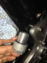
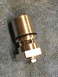
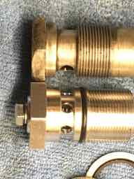
Construction
As the pictures show, two Dowty washers are supplied with the device, and there is also an O-ring between the outlets to the banjo and the threaded part of the body. With one washer between the hexagon head and the banjo the O-ring sits just inside the inner edge of the banjo. It’s hard to see what more could be done to avoid leaks, so this is encouraging.
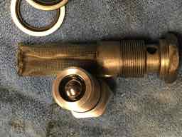
It will also be seen that the valve itself consists of a steel ball seating on a (presumably) nitrile ring. Compared to the Velo equivalent the spring is noticeably stronger. In correspondence Constant at HNW points out that this is needed because the ball is larger (and hence heavier); he also points out that the larger diameter means that less lift is needed for the same throughput of oil.
The small screw in the head is quite long and (it occurs to me after fitting, so cannot check) must among other things function to limit the possible travel of the ball. Note that if it comes loose it is likely to let air into the oil feed, with obvious consequences.
Installation
Given the last point about the inner screw, I applied a dab of Loctite and a smear of Hylomar a appropriate points in the vicinity of its head.
The large hexagon on the valve is 30 mm across flats, slightly more than the 1.125” of the standard bolt, and the valve is also slightly longer than the main body of the standard item. These features made it slightly difficult to wiggle into place and an assistant’s help was useful to gently push back the edge of the mudguard while doing so.
This point, and the friction from the two Dowty seals and the O-ring, also made engaging the thread of the valve a little tricky, and a firm grasp on a 30 mm socket was needed to get it started.
Once bolted up I had anticipated some difficulty priming the oil feed but in fact there was none.
I’m familiar with this task through having a Velo, but with those it is easy to ensure that the feed hose is topped up with oil and thus ensure minimum or no air space under the valve.
I had thought that the larger void in the HNW valve, plus the banjo, might make this more difficult.
In fact even without special measures to fill the valve and banjo I found that about 20 strokes of the kickstart was sufficient to produce a convincing flow of oil from the rocker box oil feed.
Today I took the Commando on a 40-mile ride in Kent without disaster, so clearly the valve is allowing oil to circulate when required.
Of course, the acid test — keeping oil out of the crankcase when *not* running — is still to come, but the principle works on Velos and the HNW version is more substantial than the Velo one, so I have great confidence.
- Log in to post comments
I'm no engineer, but aren't…
I'm no engineer, but aren't we tackling the symptom and not the cause? I know it would be a radical overhaul but- AFAIK, the plunger pumps on old Triumphs dont have a wet sump issue- is it realistic to re-engineer the Norton pump? Obviously a major redesign and machining facilities are required, but I'm sure there's a ready market, given that a bolt-on would be suitable for the vast majority of Nortons still running? Can we get Allen Millyard on the case?!! :0
- Log in to post comments
The AMR of Tucson mods are…
The AMR of Tucson mods are well documented if you look for them. I use them and have posted the info recently on this forum. Best leave Allen to do a V4 Commando.
- Log in to post comments
End to my wet sumping ...l
Anybody want my 850 wet sumping Twin
I Have a need, no no lust for this V4 Commando .....
Guys you’ve all helped cheer up the dribbling blues !
- Log in to post comments
I too am no engineer …
… but something that engineers have to consider is cost-effectiveness of their designs. Given the probable cost of a plunger-pump conversion, compared to a ball-and-spring valve, it seems obvious to me what the engineer's solution should be.
- Log in to post comments
Gear Pumps
The eternal wet sumping problem again. The problem is the solution! The pump should be in the sump drowned in oil. It will work forever and as long as the sump is to level keep working. Some years ago I built a flow test machine for Perkins Engines in Peterborough. Seventeen different pumps for five engine blocks, but multiple different power outputs. Immersed pumps only push oil around, and need a pressure relief valve to stop hydraulic locking in an emergency. I also worked for Mercedes F1 engines, and the engine had four oil pumps. Now we have a solution, how to achieve it? Best answers on the back of a postage stamp please.
- Log in to post comments
Now that
Small 12v scavenge pumps are cheap and easily available, I wonder if it would be worth having a take off from the 'sump' plug and a delivery back to the oil tank. Running it for a few seconds before starting should empty the crankcases. No more worries as to whether the anti drain valve is not turned on or hss stuck shut. These worries would then be replaced with ' is it leaking, or what if the pipe comes off instead!
- Log in to post comments
Good idea but the nice man…
Good idea but the nice man at Andover Norton said for years he's just been draining out the crankcase oil (using the steel to steel drain screw on their magnetic sump filter) and pouring it straight back into the tank. This at least is fail safe.
- Log in to post comments
External scavenge pump
George I think you may be on to something there. The pickup pipe could run up inside the back of the crankcase to an external union, thence to the external scavenge.
Just had a quick look, saw one like you showed, 2” Diameter, 6” long. Pop that between the gearbox cradle. BUT THEN:
The description goes on to say “Start running the car engine for a while, and start pumping when the oil temperature becomes about 50 degrees”!
Oh well, back to the drawing board!
- Log in to post comments
72 cases
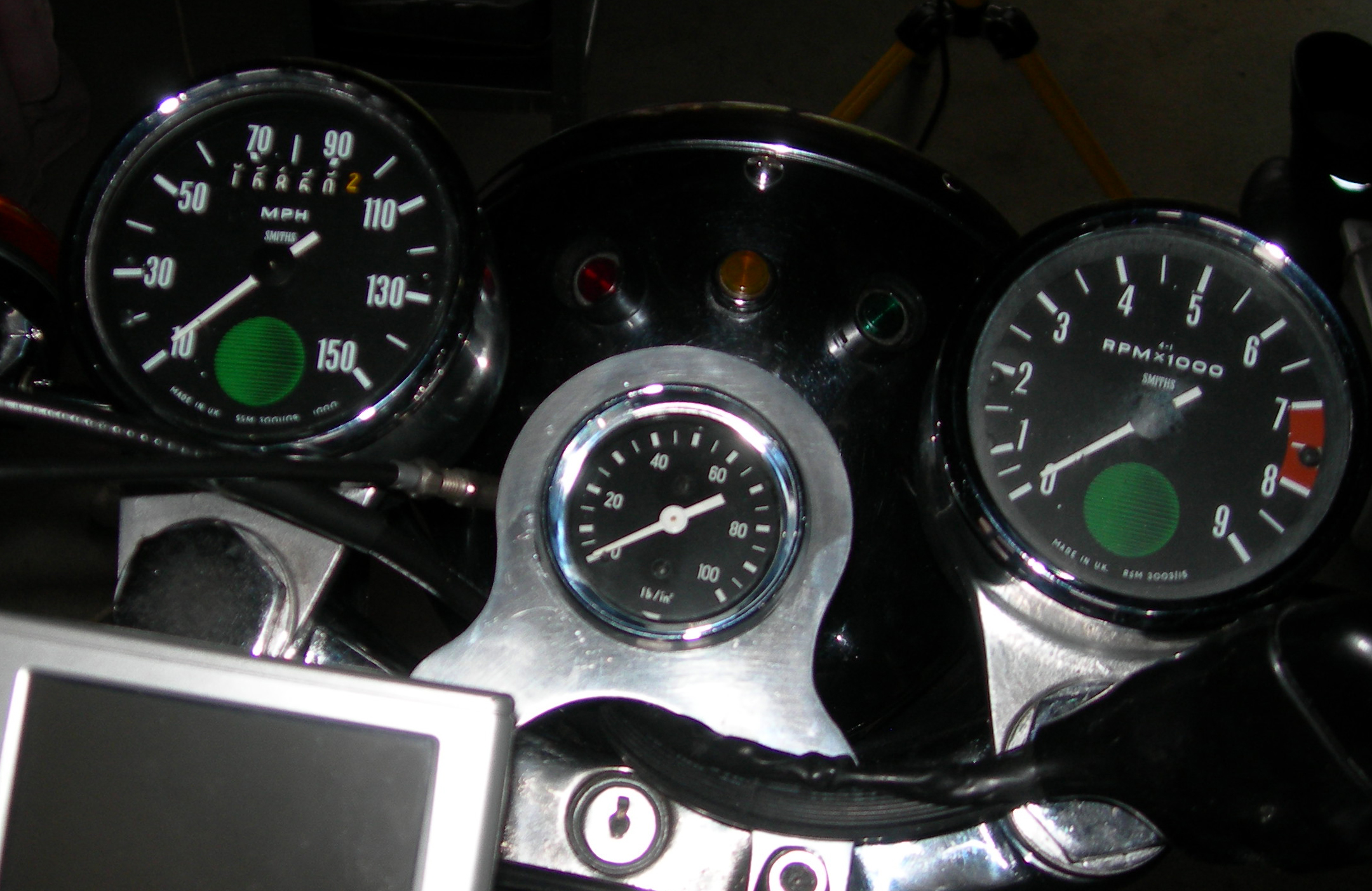
Trouble is, my 72 only has the small sump plug. I worry about the aluminium thread in the crankcase when I have to take this out every week before a weekend ride. Careful tightening - not too tight but on the other hand tight enough that it doesn’t vibrate loose and drop the oil. Just as catastrophic as a failed valve. I think I may go the HNW way and add an oil pressure alarm!
Interesting to see how Mr Wells gets on with his.
- Log in to post comments
Triumphs wet sump too
Referring to Michael Coare's earlier post, Triumphs do wet sump.
In my experience a lot more slowly than Nortons. I could leave my 1969 650 Trophy for 3 months when going off to college in the 1970s but if this extended to 6 months then it wet sumped badly.
I'd settle for that with my Commando but after a couple of months the tank was well drained. This now has a manual valve fitted in the feed line but also an oil pressure indicator switch and an oil pressure gauge just in case I forget to open the valve. I also use one of those disk lock reminder coiled leads to act as a 'Remove Before Flight' reminder. So that's belt, braces and binder twine!
I like the look of the HNW valve but am happy with my arrangement.
Andy
- Log in to post comments
Someone in the past did the…
Someone in the past did the scavenge pump mod.
I like these valves, since this summer, 3 failures, two were automatic, the other a manual type. One I know of at the Dutch rally last year. Keeps the likes of me, RGM, Norvil and others in a job.
Do I have one fitted, hell no. The bikes when sold were expected to be used daily /run often so the inherent design of of using a gear type oil pump would not be a problem.
Suddenly, now the bikes are left weeks on end the poor old pump is considered a problem, not the lack of use.
- Log in to post comments
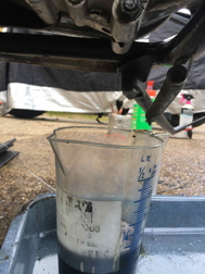
Acid test: first round
So after last week's test run I let it stand for a week before draining the sump. Here is what came out (you can see the last drop hanging from the crankcase) — 175 cc.
Previously I have found up to 1200–1400 cc after a similar interval. So far this looks like a big win.
- Log in to post comments
Living on a hill, my…
Living on a hill, my solution is to gently turn the motor over once while on the stand (and free the clutch ),then roll down the hill and engage third gear. Allow the motor to rumble away for a 100 yards then gently open the throttle and give the motor plenty of time to wake up. My old body need a slow start ,so why not the old bike. Get a hill. Good defense against a tsunami and flooding . My work partner was in Crabee Thiland on THAT day ,and I was at the beach there a couple of weeks later .
- Log in to post comments
... and I was 9 minutes into…
... and I was 9 minutes into a dive at 10 metres on the bottom in Phi Phi islands when it hit - also have a Mick Hemmings anti-wet sump valve on my Mk 3 for the past 5 years without problem ...
- Log in to post comments


Based on but not the same as the Velocette, the ball is much larger so as the ball drops under suction from the pump a larger X sectional area is created so no restriction to oil flow. The small bolt may be for bleeding/priming the oil pipe down to the pump. If the oil line to the pump is not filled with oil then the ball will not open. Gear pumps push much better than they pull hence the need to prime the oil line with oil, air is compressible so if the pumps sucks on air the suction will not open the ball.
I have a Velocette type valve in my oil line which if disturbed I prime with oil, on every first start of the day I run the bike with the oil cap open long enough so the oil being returned is fresh oil and not just the sump contents. That removes the greatest risk after a dry oil line, which is a valve stuck to its seat after a long layup.