
What would be the correct procedure - Shorten Pushrods or Valves to correct valve gear geometry?
Thanks for the reply Alan…
Thanks for the reply Alan. Now the question is how do you determine the correct pushrod length?
- Log in to post comments
Ok, Set the valve at 1/2…
Ok, Set the valve at 1/2 lift (I've replicated this by turning up some pins that locate into the valve guides) Set the adjusters so that it's inline with the Valve (or my pins). Set the cam to 1/2 lift. Now adjust the adjusters until all clearance is taken up measuring this amount. This would be the amount to remove from the pushrod (dividing by 1.13)?
I've not done this before nor can I find anything to read on the subject specific to the Norton - Theory yes but not in practice.
- Log in to post comments
The theory...
The theory I have mentioned is universal to ALL internal combustion engines work with the same principal to get maximum efficiency from the engine. One assumes the manufacturer got it right in the first manufacture of the engine, but then WE and the Norton Factory come along putting compression ratios up and forgetting push-rods/valves and rocker geometry. Result- push-rods and valve stems get 'fiddled' with and we are all at sea.
- Log in to post comments
Timing is perfect regarding…
Timing is perfect regarding to the job I'm doing on my Commando right now.
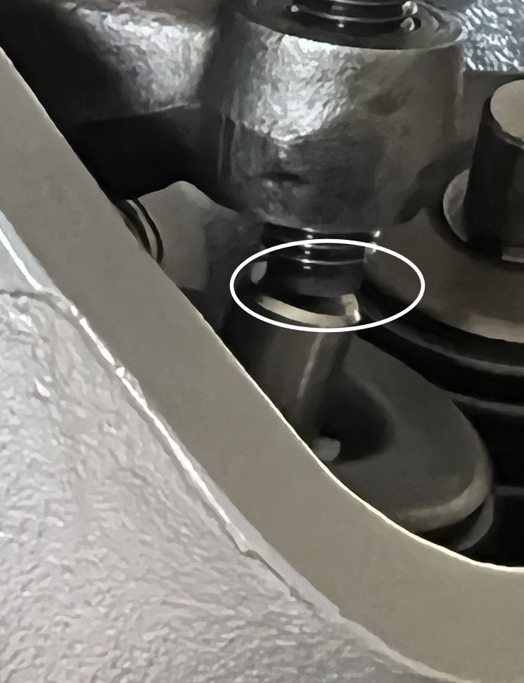
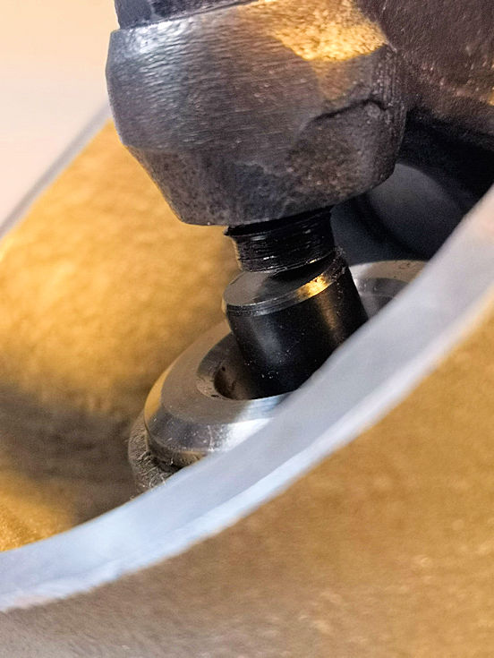
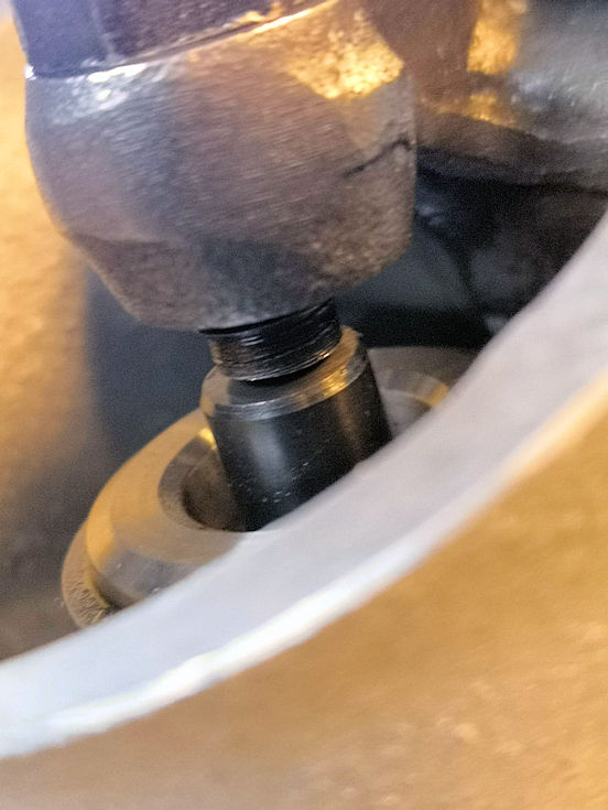
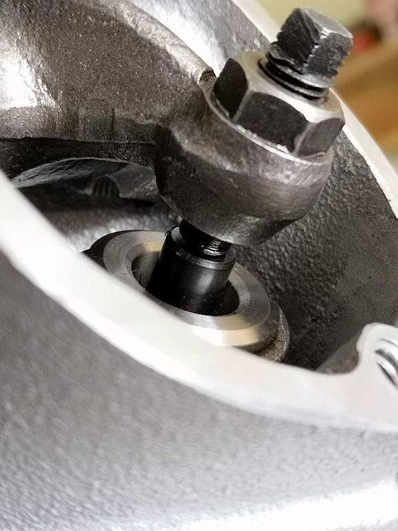
I'm a bit less so, so I tiptoe in to try and ensure that the geometry of the rocker arms on the first 850 I'm putting back together is as close as possible to what it should be. Unfortunately the cylinder is already in place, and I find the angle of the adjuster on the valve stem odd when the valve is fully closed. Is the valve stem too long? Or is this normal on the Commando because the adjustment screw is slightly rounded and when the valve is fully open, under full load, the adjuster will rest on the valve stem over its entire surface?
Putting a cap lash won't be a solution to it, so leave it like that or shorten the stem? Or put a mushroom adjuster screw? Or try to find a ball end one?
Translated by deepl.com
- Log in to post comments
Very difficult to see whats…
- Log in to post comments
It does not help that Norton…
- Log in to post comments
Here's a brighter photo, I…
- Log in to post comments
What's the recommended trick…
- Log in to post comments
A second photo from exactly…
- Log in to post comments
Christian hello - like the…
- Log in to post comments
Looks a long way out. I…
- Log in to post comments
My RH4 head is currently…
- Log in to post comments
The only way forward is to…
- Log in to post comments
My thoughts are at first you…
- Log in to post comments
My cylinder head, a Fullauto…
- Log in to post comments
" When they decided to have…
- Log in to post comments
Simple, the drawings for the…
- Log in to post comments
If any Commando owner has a…
- Log in to post comments
Latest news via latest…
Latest news via latest photos
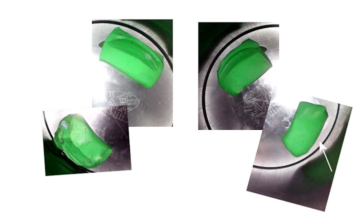
LH EX close
LH EX mid-lift
 LH EX open
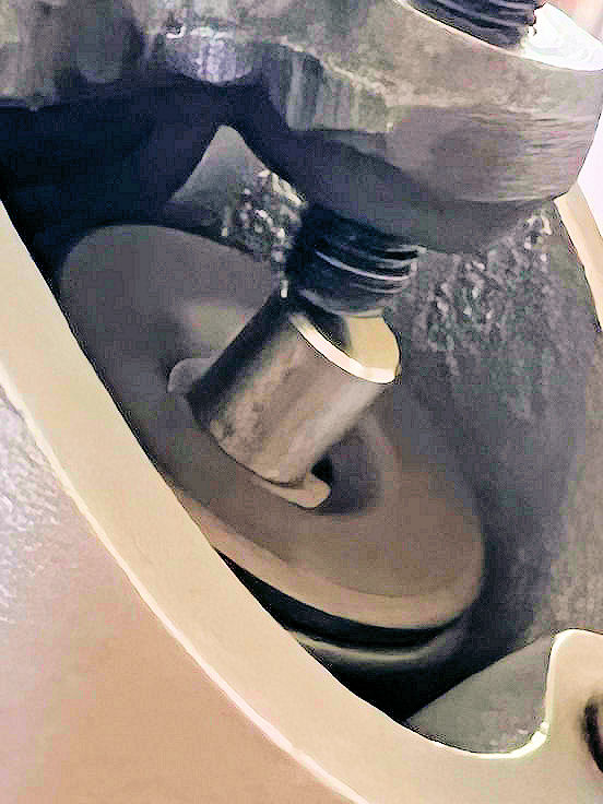
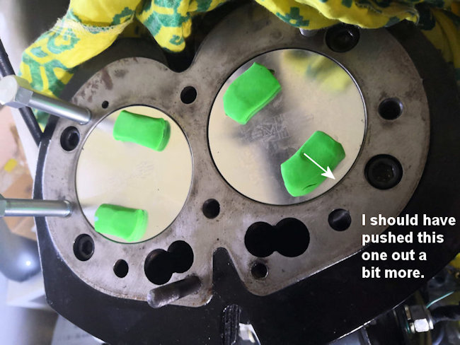 Checking valve/piston clearance, another view from the plug hole, which tells us that the seats were probably not pushed in. And that the exhaust valves come really close the cylinder bore.
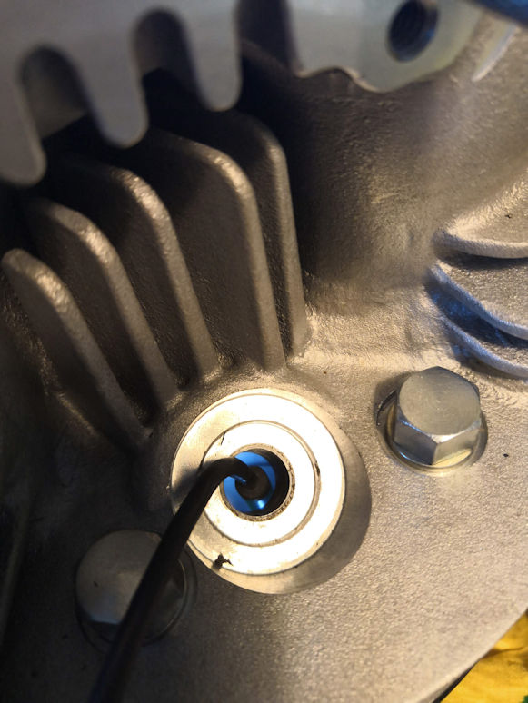 Head on with a borescope in.
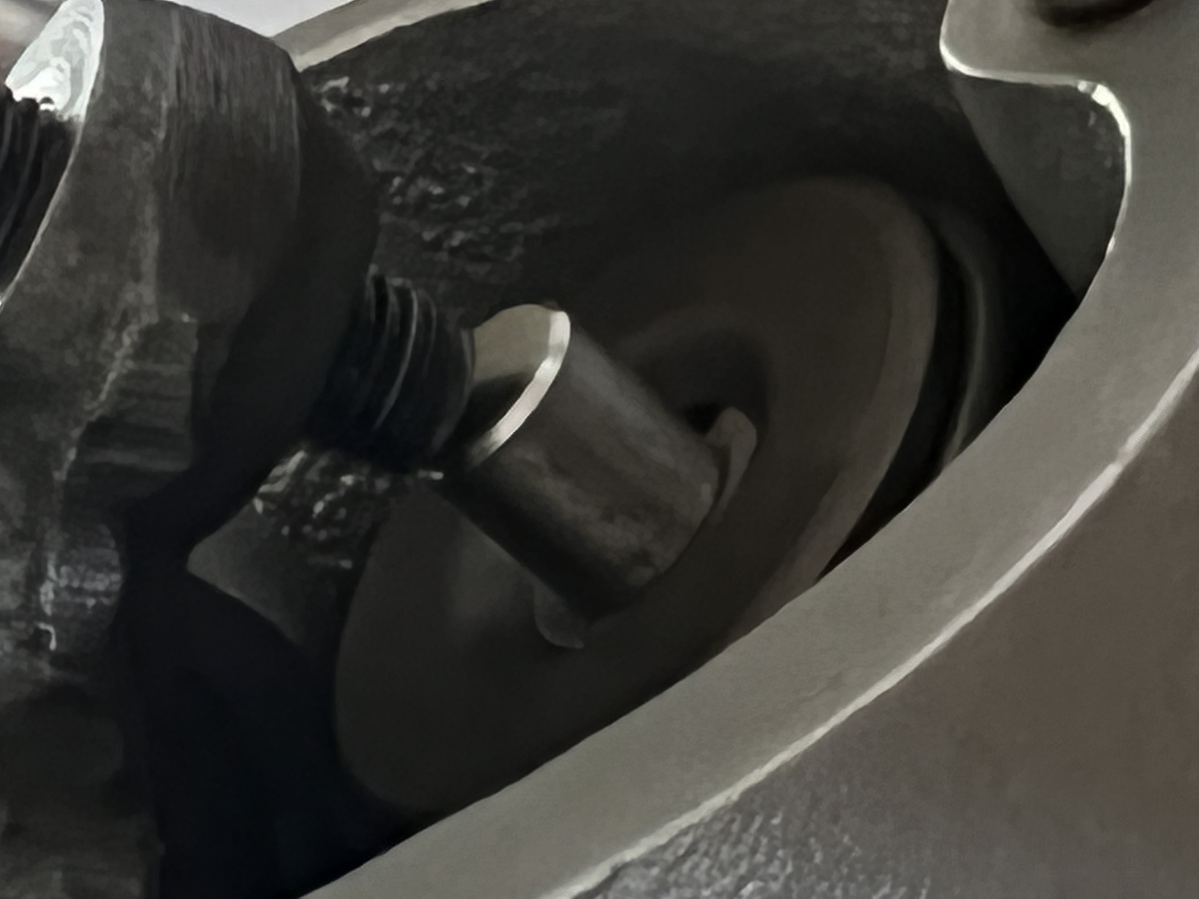
 And that the exhaust valves come really close the cylinder bore.
What do you, specialists, think about that? Could I leave it like that or not.
And that the exhaust valves come really close the cylinder bore.
What do you, specialists, think about that? Could I leave it like that or not.
- Log in to post comments
Longer pushrod with adjuster…
- Log in to post comments
Hello again Christian - The…
- Log in to post comments
Of course, longer pushrods…
- Log in to post comments
Hello Howard, You're right,…
- Log in to post comments
Valve spring pressure is…
- Log in to post comments
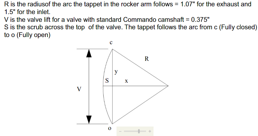
First let us understand the basic principles of Valve geometry. It is easy to understand but very hard to measure. The maximum efficiency of the system is when the valve is at HALF lift, the valve rocker should be at RIGHT ANGLES to the valve stem. What affects this? valve length, push-rod length, and compression ratio, and cam lift, and rocker lengths/ratio. In our usual commando scenario, the rocker length/ratio and cam lift hardly ever change, but the others do!
Going back to the original question it is far easier to change a push-rod length than anything else in the system. Have fun!