What would be the correct procedure - Shorten Pushrods or Valves to correct valve gear geometry?
Thanks for the reply Alan…
Thanks for the reply Alan. Now the question is how do you determine the correct pushrod length?
- Log in to post comments
Ok, Set the valve at 1/2…
Ok, Set the valve at 1/2 lift (I've replicated this by turning up some pins that locate into the valve guides) Set the adjusters so that it's inline with the Valve (or my pins). Set the cam to 1/2 lift. Now adjust the adjusters until all clearance is taken up measuring this amount. This would be the amount to remove from the pushrod (dividing by 1.13)?
I've not done this before nor can I find anything to read on the subject specific to the Norton - Theory yes but not in practice.
- Log in to post comments
The theory...
The theory I have mentioned is universal to ALL internal combustion engines work with the same principal to get maximum efficiency from the engine. One assumes the manufacturer got it right in the first manufacture of the engine, but then WE and the Norton Factory come along putting compression ratios up and forgetting push-rods/valves and rocker geometry. Result- push-rods and valve stems get 'fiddled' with and we are all at sea.
- Log in to post comments
Timing is perfect regarding…
Timing is perfect regarding to the job I'm doing on my Commando right now.
I'm a bit less so, so I tiptoe in to try and ensure that the geometry of the rocker arms on the first 850 I'm putting back together is as close as possible to what it should be.
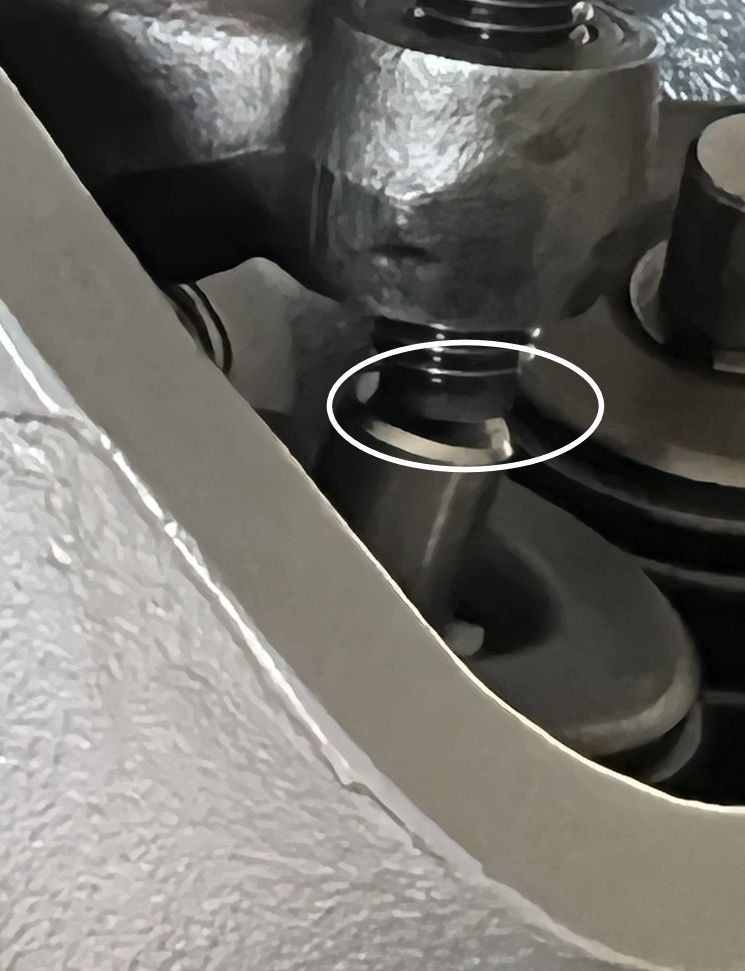
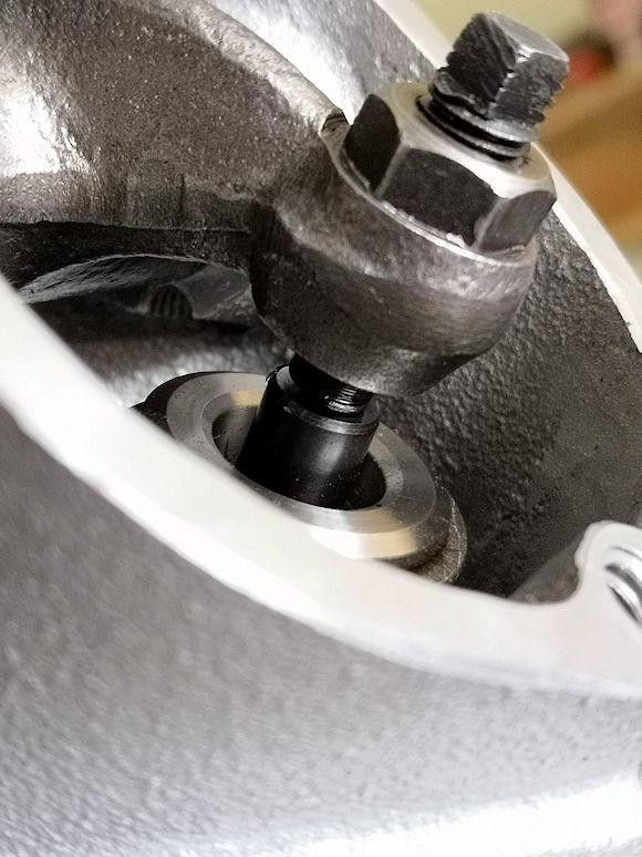
Unfortunately the cylinder is already in place, and I find the angle of the adjuster on the valve stem odd when the valve is fully closed.
Is the valve stem too long?
Or is this normal on the Commando because the adjustment screw is slightly rounded and when the valve is fully open, under full load, the adjuster will rest on the valve stem over its entire surface?
Putting a cap lash won't be a solution to it, so leave it like that or shorten the stem? Or put a mushroom adjuster screw? Or try to find a ball end one?
Translated by deepl.com
- Log in to post comments
Very difficult to see whats…
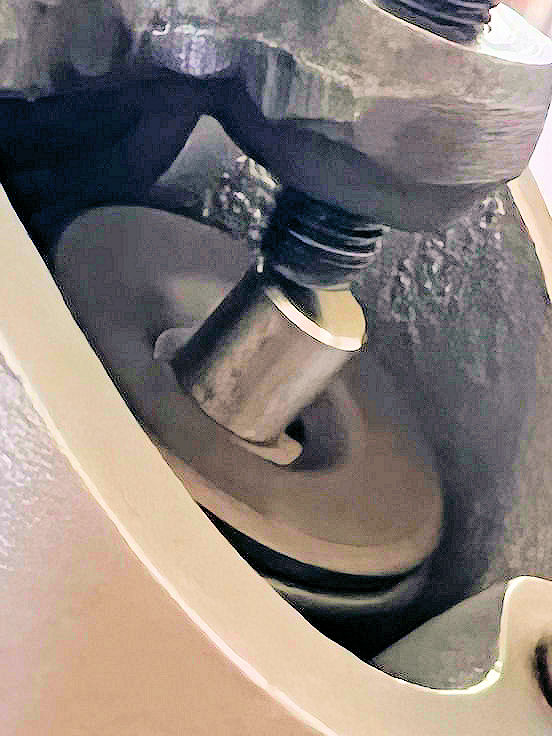
Very difficult to see whats happening from your photo , but it would appear that the valves too long and pushrods too short?
- Log in to post comments
Here's a brighter photo, I…
Here's a brighter photo, I hope it will help see the situation better.
- Log in to post comments
It does not help that Norton…
It does not help that Norton engineers / suppliers back in the early '70's cocked up the Commando valve lengths. When they decided to have valve stems with stellite tips they stipulated the length of the tip but it seems that they mucked up the calculations and this length was added to the existing length and not worked into the length they already had. The pushrods as we know we never changed to compensate this, so it seems they never even knew they had mucked up.
Ever wondered why late Atlas owners never mention this, the valves are still made to the original shorter length.
- Log in to post comments
What's the recommended trick…
What's the recommended trick to fix that today?
- Log in to post comments
" When they decided to have…
" When they decided to have valve stems with stellite tips they stipulated the length of the tip but it seems that they mucked up the calculations and this length was added to the existing length and not worked into the length they already had"
I've not read this before - can I ask the source of the information?
Cheers
- Log in to post comments
Simple, the drawings for the…
Simple, the drawings for the valves and the push rods.
- Log in to post comments
A second photo from exactly…
A second photo from exactly the same angle but with the valve fully open would help. Followed by one half way between (more difficult to estimate)
- Log in to post comments
Christian hello - like the…
Christian hello - like the others who've commented I am intrigued by your image. You didn't specify what camshaft and followers that you're using. Is that image taken at the tappet setting point with an 8 thou clearance ? Can you send another image at the valve fully open point as Geoff has suggested. Ashley has alluded to a change to the valve geometry that was incorporated after engine number 125871 to all Atlas and 650 motors. The valve stem lengths were lengthened by 0.1 inch and the pushrods shortened by a similar amount. It appears that the Commandos got the longer valve stem but may have kept the longer pushrods. If you were to fit a valve stem cap and readjust your tappet clearances you may get a better point of contact between the adjuster and the valve cap but I should like to see the image with the valve fully open. I had similar problems racing a 750 Commando many years ago and as Al says, these only get worse when skimmed heads, hot cams and radiussed followers are added to the mix. regards, howard
- Log in to post comments
Looks a long way out. I…
Looks a long way out. I would wonder if the valve seats and guides have been moved to fit bigger valves /re-angled valves as is sometimes done when "hoppingup" a motor .Also very sunk seats can produce a similar effect. As others have said , how about a short video of the valve action from closed to open and back to closed. leaving things as they are will wear out guides ,valve tips and tappets in short order ,i had a tappet snap a lump off when a too long valve found its way in. Looks like plenty of spare valve stem could be removed and hard lash caps fitted along with longer rods.
- Log in to post comments
My RH4 head is currently…
My RH4 head is currently uninstalled. The rocker adjuster has simply been set at mid position to check contact with the valve stem. As can be seen, it looks very similar to Christian's photo, with the adjuster touching right at the inboard edge of the stem. The head had new exhaust seats fitted by Norman White, but the guides were not touched and it is otherwise completely standard. The valves came from AN. The inlet valve adjusters contact dead centre on the stem.
I am similarly in a quandary about what the solution is.
- Log in to post comments
The only way forward is to…
The only way forward is to view the action in motion.
- Log in to post comments
My thoughts are at first you…
My thoughts are at first you need to establish if the rocker arm is at 90 degrees to the valve stem with the valve at half lift?
- Log in to post comments
My cylinder head, a Fullauto…
My cylinder head, a Fullauto, went to THE US specialist and he fitted Kibblewhite valves. The camshaft and lifters are stock, pistons are MAP, the same as original, except for the weight.
I temporarily installed the rocker arms with 4 slightly undersized shafts, to test the clearance between pistons and valves, and fitted the cylinder head.
I didn't think to take any photos, but the geometry of the valve stem rocker arm was curious. At least for me, who's putting a Norton 850 cylinder head back together for the first time.
Whereas with the original cylinder head, the "original" pistons had a very slight mark from the valves. Here there was barely a trace on the clay on the intake side of the RH cylinder.
I'll have to redo the test with exactly the same thickness of clay under the 4 valves, because the result could suggest that the seats may have been lowered because at TDC new pistons are flush like older.
For those of you who might be thinking about it, I asked the specialist who worked on the cylinder head what he thought about it and I still haven't heard back from him.
- Log in to post comments
If any Commando owner has a…
If any Commando owner has a shorter Atlas exhaust valve, fit that see the difference.
- Log in to post comments
Latest news via latest…
Latest news via latest photos
LH EX close
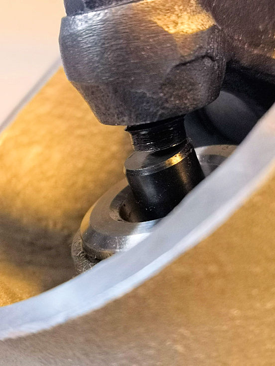
LH EX mid-lift
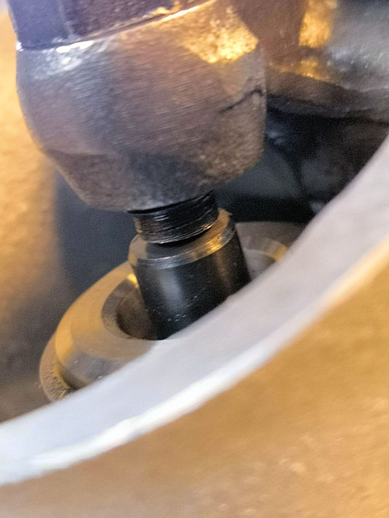
LH EX open
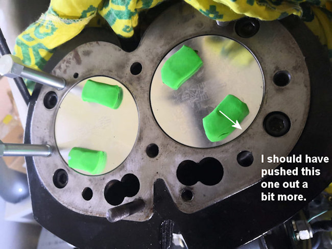
Checking valve/piston clearance, another view from the plug hole, which tells us that the seats were probably not pushed in. And that the exhaust valves come really close the cylinder bore.
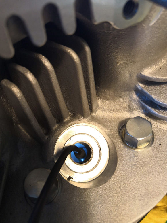
Head on with a borescope in.
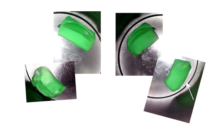
And that the exhaust valves come really close the cylinder bore.
What do you, specialists, think about that? Could I leave it like that or not.
- Log in to post comments
Longer pushrod with adjuster…
Longer pushrod with adjuster raised would be the easiest way to make it better. Looks like you would benefit from about 1/8" longer rods. But there wouldn't be much of the adjuster projecting unless valves were shorter.
Not sure about your concern about valves. They don't seem to be hitting pistons (about 0.040" is often said to be minimum recommended clearance). The valve edges are much closer to the bores on my 88SS.
But...surely the main problem might be that if there's too much scrub, there will be premature wear and you might want to replace valves when that takes place. So you might as well wait and see?
- Log in to post comments
Of course, longer pushrods…
Of course, longer pushrods would be nice. For the adjusters, do you know if 06.7546AK (socket head) are a bit longer than 06.7546? Maybe that would do the job?
This is the first time I'm working on a Norton engine and I'm just wondering if everything is normal. Or not.
As for the valves, they don't touch the pistons, so that's pretty good.
And I'd prefer not to wear out the guides prematurely.
Translated by deepl.com
- Log in to post comments
Hello again Christian - The…
Hello again Christian - The image of the adjuster impact point in your entry on 10th April seems to be quite different to the more recent images. Much more of the valve stem is in view above the valve cap. The colletts seem to be further down the stem. Are the colletts the same in each image ? I am getting the impression that something has changed since the first image was taken. Please can you clarify by measuring from the top face of the valve cap to the face at the top of the valve stem. I am seeing the cap further up the stem in the first image meaning the colletts must have a smaller o/d. Regards, Howard
- Log in to post comments
Hello Howard, You're right,…
Hello Howard,
You're right, thank you for your sharp eye. As I explained on 11 April, I put it together for valve clearance test without taking any photos. The one I posted first was found on the Net. The others are from my engine. It's Kibblewhite valves and springs.
- Log in to post comments
Valve spring pressure is…
Valve spring pressure is roughly twice as much at full lift than at no lift. Therefore, surely the rocker should be level with the top of the valve at 2/3 lift, not at half lift? The direction side thrust would then be more off centre from the valve when at rest than when at full lift. So yours might be OK.
- Log in to post comments


First let us understand the basic principles of Valve geometry. It is easy to understand but very hard to measure. The maximum efficiency of the system is when the valve is at HALF lift, the valve rocker should be at RIGHT ANGLES to the valve stem. What affects this? valve length, push-rod length, and compression ratio, and cam lift, and rocker lengths/ratio. In our usual commando scenario, the rocker length/ratio and cam lift hardly ever change, but the others do!
Going back to the original question it is far easier to change a push-rod length than anything else in the system. Have fun!